Electric Braking
Braking
The braking system is one of the most critical functions upon which the safety of the entire vehicle dependent. The two most crucial function of the braking system are to stop the vehicle in the shortest possible distance in case of emergency and to maintain control over the vehicle's direction.
Mostly a brake is considered as a mechanical device that inhibits motion by absorbing energy from a moving system. It is used for slowing or stopping a moving vehicle, wheel, axle, or to prevent its motion, most often accomplished by means of friction.
The most commonly used braking system in Vehicles are:-
1. Mechanical braking system:
The mechanical braking system powers the hand brake or emergency brake. It is the type of braking system in which the brake force applied on the brake pedal is carried to the final brake drum or disc rotor by the various mechanical linkages like cylindrical rods, fulcrums, springs, etc. In order to stop the vehicle.
a) Disc Brake
The disc brake is a mechanism for slowing or stopping the rotation of a wheel from its motion. A disc brake is normally made of cast iron, but in some cases, it is also made of composites such as carbon-carbon or ceramic-matrix composites. This is linked to the wheel and/or the axle. To stop the wheel, friction material in the form of brake pads is forced against both sides of the disc. Friction caused, on the disc wheel will slow or stop.
b) Drum Brake
A drum brake is a traditional break in which the friction is caused by a set of shoes or pads that press against a rotating drum-shaped part called a brake drum.
2. Engine Braking System
Engine braking occurs when the retarding forces within an engine are used to slow down a motor vehicle, as opposed to using additional external braking mechanisms such as friction brakes or magnetic brakes. Traffic regulations in many countries require trucks to always drive with an engaged gear, which in turn provides a certain amount of engine braking (viscous losses to the engine oil and air pumped through the engine and friction losses to the cylinder walls and bearings) when no accelerator pedal is applied.
a) Vaccum Braking (Gasoline Engine)
The term "engine braking" refers to the braking effect that occurs in gasoline engines when the accelerator pedal is released. This causes fuel injection to cease and the throttle valve to close almost completely, greatly restricting forced airflow from, say e.g., a turbo. The latter of which causes a strong manifold vacuum for which the cylinders have to work against—sapping much of the potential energy out of the system over time, and producing the majority of the engine-braking effect. This vacuum manifold effect can often be amplified by a down-shift, which induces a faster spinning drive chain to engage with the engine.
Engine braking is a viable method of controlling the speed at which a vehicle travels downhill. By shifting to lower gears in a manual transmission or selecting the "second/low gear" mode on an automatic transmission, engine braking reduces the need to repeatedly apply the foot brake, lowering the risk of the brakes overheating. While some of the braking force is produced due to friction in the drive train, this is negligible compared to the effect from the manifold vacuum caused by the air-flow restriction.
b) Compression Release Brake (Diesel Engine)`
Diesel engines in personal cars provide little engine braking as they are not equipped with a throttle body and thus cannot draw a vacuum in the intake manifold.
A compression release brake (also known as a Jacobs brake or "jake brake"), is the type of brake most commonly confused with real engine braking; it is used mainly in large diesel trucks and works by opening the exhaust valves at the top of the compression stroke, so the large amount of energy stored in that compressed air is not returned to the crankshaft but is released into the atmosphere.
Normally, during the compression stroke, energy is used as the upward-traveling piston compresses air in the cylinder; the compressed air then acts as a compressed spring and pushes the piston back down. However, with the jake brake in operation, the compressed air is suddenly released just before the piston begins its downward travel. (This sudden release of compressed air creates audible sound waves similar to the expanding gases escaping from the muzzle of a firearm.) Having lost the energy stored within the compressed air, there is no "spring back" so the engine must expend yet more energy pulling the piston back down again.
The most commonly used braking system in Electric Vehicles are:-
1. Electromagnetic braking system
Electromagnetic braking systems can be found in many modern and hybrid vehicles. The electromagnetic braking system uses the principle of electromagnetism to achieve frictionless braking. This serves to increase the life span and reliability of brakes. Also, traditional braking systems are prone to slipping while this is backed with quick magnetic brakes. So without friction or the need for lubrication, this technology is preferred in hybrids. Also, it is quite modest in size compared to the traditional braking systems. It is mostly used in trams and trains.
To make electromagnetic brakes work, a magnetic flux when passed in a direction perpendicular to the rotating direction of the wheel, we see rapid current flowing in a direction opposite to the rotation of the wheel. This creates an opposing force to the wheel rotation and it slows down the wheel.
Electromagnetic braking is more effective at a higher speed as the rate of change of flux is higher, and at lower speeds, mechanical brakes must be used to stop the vehicle.
2. Dynamic Braking
The conversion of the mechanical energy of a rotating shaft to electrical energy (electric generator) to decrease reduce the speed of the vehicle is called dynamic braking. The dynamic braking slows down a moving vehicle or object by converting its kinetic energy into a form that can be either used immediately or stored until needed. In this mechanism, the electric traction motor uses the vehicle's momentum to recover energy that would otherwise be lost to the brake discs as heat. The interactions of armature windings with a (relatively) moving external magnetic field, with the armature connected to an electrical circuit with either a power supply (motor) or power receptor (generator). Since the role of the electrical/mechanical energy converting device is determined by which interface (mechanical or electrical) provides or receives energy, the same device can fulfill the role of either a motor or a generator. In dynamic braking, the traction motor is switched into the role of a generator by switching from a supply circuit to a receptor circuit while applying electric current to the field coils that generate the magnetic field (excitation).
The amount of resistance applied to the rotating shaft (braking power) equals the rate of electrical power generation plus some efficiency loss. That is proportional to the strength of the magnetic field, controlled by the current in the field coils, and the rate at which the armature and magnetic field rotate against each other, determined by the rotation of the wheels and the ratio of power shaft to wheel rotation. The amount of braking power is controlled by varying the strength of the magnetic field through the amount of current in the field coils. As the rate of electrical power generation, and conversely braking power, are proportional to the rate at which the power shaft is spinning, a stronger magnetic field is required to maintain braking power as speed decreases and there is a lower limit at which dynamic braking can be effective depending on the current available for application to the field coils.
The two main methods of managing the electricity generated during dynamic braking are rheostatic braking and regenerative braking, as described below.
For permanent magnet motors, dynamic braking is easily achieved by shorting the motor terminals, thus bringing the motor to a fast abrupt stop. This method, however, dissipates all the energy as heat in the motor itself, and so cannot be used in anything other than low-power intermittent applications due to cooling limitations. It is not suitable for traction applications.
a) Rheostatic Braking
The electrical energy produced by the motors is dissipated as heat by a bank of onboard resistors, referred to as the braking grid. Large cooling fans are necessary to protect the resistors from damage. Modern systems have thermal monitoring, so, if the temperature of the bank becomes excessive, it will be switched off, and the braking will revert to friction only.
b) Regenerative Braking
The process of regenerative braking is employed whereby the current produced during braking is fed back into the power supply system for use by other traction units, instead of being wasted as heat. It is normal practice to incorporate both regenerative and rheostatic braking in electrified systems. If the power supply system is not "receptive", i.e. incapable of absorbing the current, the system will default to the rheostatic mode in order to provide the braking effect.
In electric railways, the electricity generated is fed back into the traction power supply. In battery electric and hybrid electric vehicles, the energy is stored chemically in a battery, electrically in a bank of capacitors, or mechanically in a rotating flywheel.
Drive Cycle
A driving cycle is a series of data points representing the speed of a vehicle versus time. Driving cycles are produced by different countries and organizations to assess the performance of vehicles in various ways, as for instance fuel consumption, electric vehicle autonomy, and polluting emissions.
The FTP-75 (Federal Test Procedure) has been used for emission certification and fuel economy testing of light-duty vehicles in the United States. The test is often referred to as simply ‘FTP’ (this should not be confused with the FTP test for heavy-duty engines).
The FTP-75 and the FTP-72 are two variants of the EPA Urban Dynamometer Driving Schedule (UDDS). The FTP-75 cycle is derived from the FTP-72 by adding a third phase of 505 s, identical to the first phase of FTP-72 but with a hot start. The third phase starts after the engine is stopped for 10 minutes.
Thus, the entire FTP-75 cycle consists of the following segments:
Braking Energy
The braking energy requirement can be expressed in terms of the change in the kinetic energy of the vehicle as the kinetic energy (KE) of a vehicle is the energy that it possesses due to its motion.
`KE=1/2mv^2` where
`KE` is the Kinetic Energy in Joules
`m` is the mass of the moving object in kg
`v` is the velocity of the moving object in m/s
Brake energy can be expressed as a change in kinetic energy
`DeltaKE=1/2m(v_f^2-v_i^2)` where
`DeltaKE` is the change in Kinetic Energy in Joules
`v_f` is the final speed in m/s
`v_i` is the initial speed in m/s
`m` is the mass of the vehicle in kg
Matlab script to find the braking energy
% program to calculate the braking energy for FTP75 drive cycle
clc
clear all
close all

% assumptions
m=1500; % let mass of vehicle with load be 1500kg

% loading FTP75 drive cycle
load('FTP75');

% braking energy can be calculated using change in kinetic energy
% brake enegy=delta ke=0.5m(v2^2-v1^2)

ke=0.5*m.*FTP75(2,:);% instantaneous kinetic energy

% in braking the kinetic energy will decrease as the velocity decreases
for i=2:4949
    be(1)=0;% initially at the start the braking energy is zero
    tbe(1)=0;% total brake energy at starting is zero
    if ke(i)<ke(i-1)
        be(i)=(ke(i-1)-ke(i))/1000;
    else
        be(i)=0;
    end
    tbe(i)=tbe(i-1)+be(i);%total braking energy
end

%drive cycle plot
subplot(2,1,1)
plot(FTP75(1,:),FTP75(2,:))
title('Drive Cycle FTP75')
xlabel('Time sec');
ylabel('Speed m/s')
grid on

%braking energy plot
subplot(2,1,2)
plot(FTP75(1,:),tbe)
title('Brake Energy')
xlabel('Time sec');
ylabel('Energy kJ')
grid on
Result
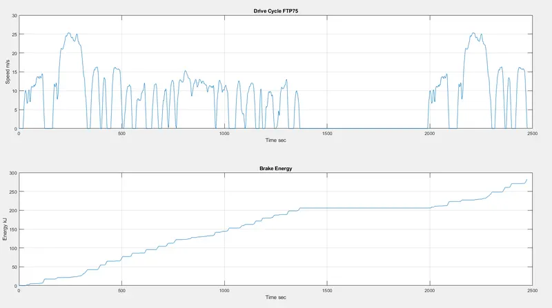
The FTP75 drive cycle requires 283.18kJ braking energy to run for 2474 seconds.
Problem faced with Braking at Higher Speed
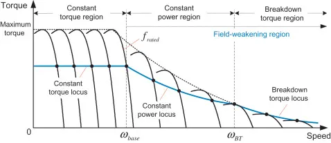
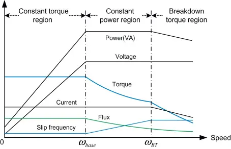
The electric motor cannot produce higher torque at a higher speed similar to starting torque because in order to achieve higher speeds the motor is operated in the field weakening region, where the flux density is reduced resulting in lower torque from the motor at higher speeds. Thus the torque produced at higher speeds is less compared to torque at lower speeds.
While developing a high brake torque at high speed the rotor is made to rotate in a stationary magnetic flux of high density thus the motor acts as a generator. Due to the high rate of change of flux inside the rotor a high magnitude of the current is generated is dissipated as heat and some amount of current is used to charge the battery. Due to the limiting design factors such as charging rate, limiting charging current, and cooling limitation the heat produced can damage the windings. Hence for safe working conditions, it is not practical to develop high braking torque. While at lower speed the rate of change of flux inside the rotor is less thus developing higher brake torque at a lower speed.
Operation regions of an induction motor
Capability curve of typical Induction Motor
Coordination of Mechanical and Electrical brakes
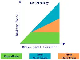
The electrical brakes alone cannot meet the braking torque requirements thus in Electric Vehicles and Hybrid Electric vehicles mechanical braking system is incorporated in order to achieve the desired control over the vehicle. Considering that regenerative braking is a key requirement the control and coordination of both mechanical and electrical braking are essential.
The two major factors affecting the design of EV Braking System are
1. Braking Power requirement
2. Braking Energy recovery
Based on the braking requirement the braking system techniques for control and coordination of braking system are designed.
Three Basic braking strategies are
1. Series Brake System
a) Series Brake - Optimal Feel
The series braking system with optimal feel consists of a braking controller that controls the braking forces on the front and rear wheels. The control objective is to minimize the stopping distance and optimize the driver’s feel.
b) Series Brake- Optimal Energy Recovery
The principle of the series braking system with optimal energy recovery is to recover the braking energy as much as possible in the condition of meeting the total braking force demanded for the given deceleration.
2. Parallel Brake System
The parallel brake system includes both an electrical (regenerative) brake and a mechanical brake, which produce braking forces is parallel and simultaneously.
Nissan-Electric Driven Intelligent Brake
The EDIB (Electric Driven Intelligent Brake) allows and controls optimization of the regenerative brake and regular friction brake (hydraulic brake). The Electric Driven Intelligent Brake, utilizes the vehicle’s electric motor to directly operate the brake cylinders. When the driver steps on the brake pedal, the necessary braking force is maintained while the hydraulic pressure of the friction brake is controlled to help maximize the energy regeneration of the hybrid motor. Because of its simple structure, in which the motor directly operates the brake cylinders.