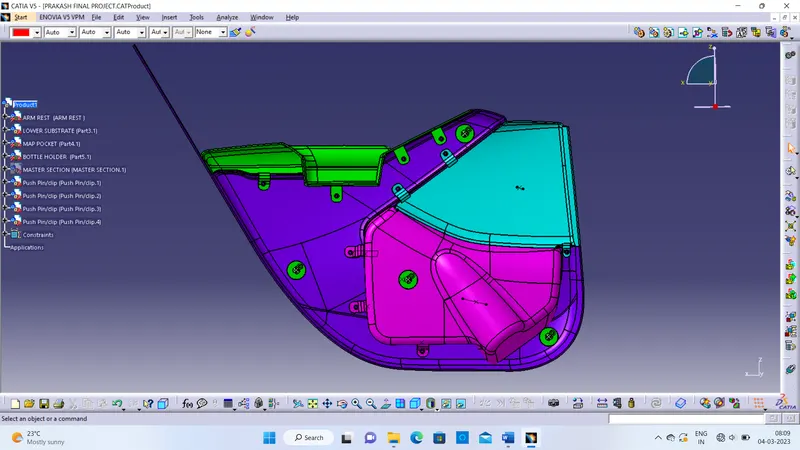
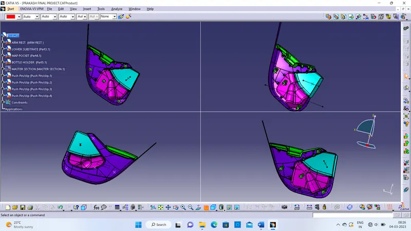
DOOR TRIM PANEL DEVELOPMENT PROJECT
DOOR TRIM PANEL
AIM:To develop a Door Panel of an automotive plastic component
- To create an assembly and working in a different surface of the given class A surface into different parts of the door trim panel. To create a point, tooling axis and perform a draft analysis on the class A surface of each part
- To create class B and class C surface and convert it into closed body
- To perform draft analysis and solid analysis on the close body of each part
- To create engineering features (Heat stakes, Locators, Dog House) to join the parts of the door trim panel
- To assemble push pins to the door panel.
INTRODUCTION:
- Door panels serve as an interface between the interior of the car and the inner workings of the door, and between vehicle occupants and the door. Doors currently have an inner full-width panel consisting of electronic windows, central locking system, and speakers. These panels typically consist of a foamed core covered with either textiles or plastics, injection moulding being the most common method. Other features that add to the vehicle's aesthetic, functionality, and ergonomics are usually included in the door panel. Armrests, switches, or other controls for the windows
MAJOR COMPONENTS OF DOOR PANEL:
- Lower substrate
- Door arm rest
- Bottle holder
- Map pocket
TASK TO PERFORM IN THIS PROJECT:
- Creation Of Tooling Axis
- Creation Of Class A, B, And C Surface
- Creation Of Closed Surface of All the Components
- Creation Of B Side Features
- To Perform Draft Analysis
Let’s create each part step by step
PROCEDURE:
- Lower substrate
CREATION OF TOOLING AXIS:
- The clearance checking along all the axis direction will be done by creating an intersection along an axis on a plane with the model and constructing two lines contact with the walls, the line bisecting the two lines and passing through the pointwill be the tooling axis
- We Will Create a Tooling Axis for The All the Components. For Clearing the Tooling Axis for Door Arm Rest, We Have to Use the Compass and Lock the Orientation Where the Tooling Axis Show the All Green in The Draft Analysis Under The 3 Degree Angle. As For the Lower Substrate and Map Pocket, We Will Directly Go for The Natural Tooling Axis Y-Direction
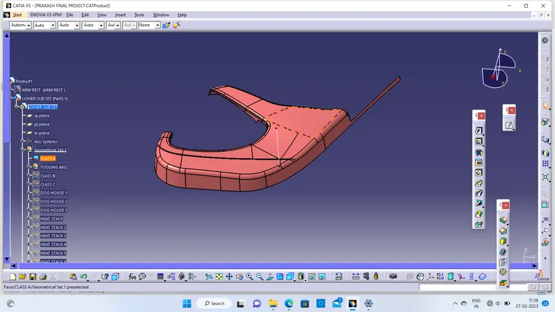
- CLASS A
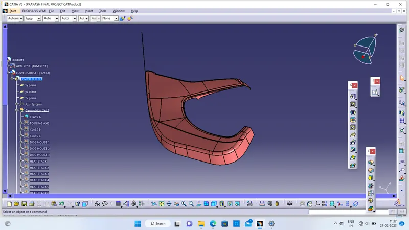
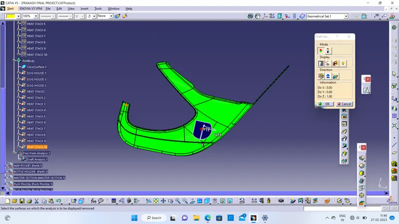
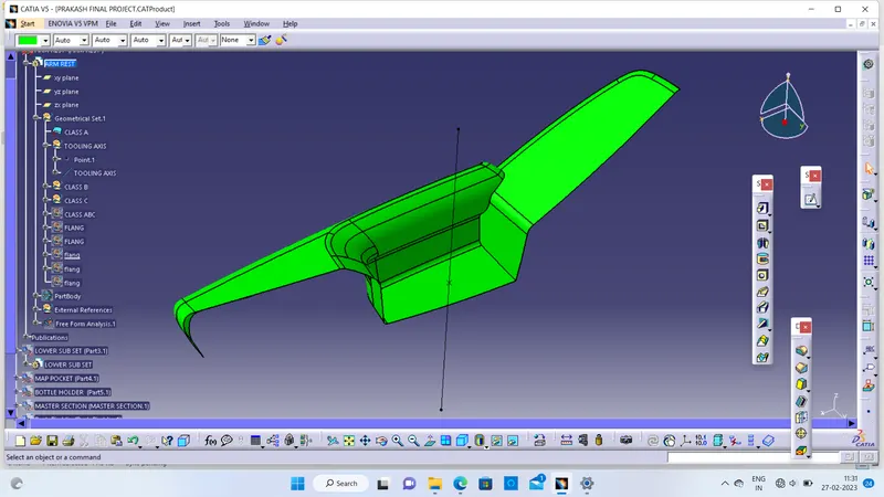
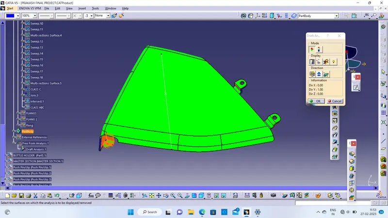
DRAFT ANALYSIS
Draft analysis
Click on draft analysis and adjust the compass to the tooling axis and click on compass symbol and rearrange the compass the tooling axis and lock it
Then click on surface of the part body
- CLASS B
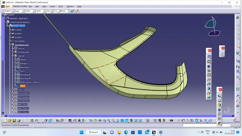
CREATION OF CLASS B
Class B surface is the surface which is created with the help of class A surface as the reference.
The class B surface is the surface where all the necessary attachments and supports of the component is made
The main parts without the edge fillets are extracted and untrimmed and then they are extrapolated for better view.
The extrapolated parts are then made offset with reference to the class A with the thickness of the component, here thickness of the component for base bracket is 2.5 mm.
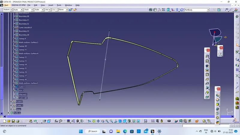
- CLASS C
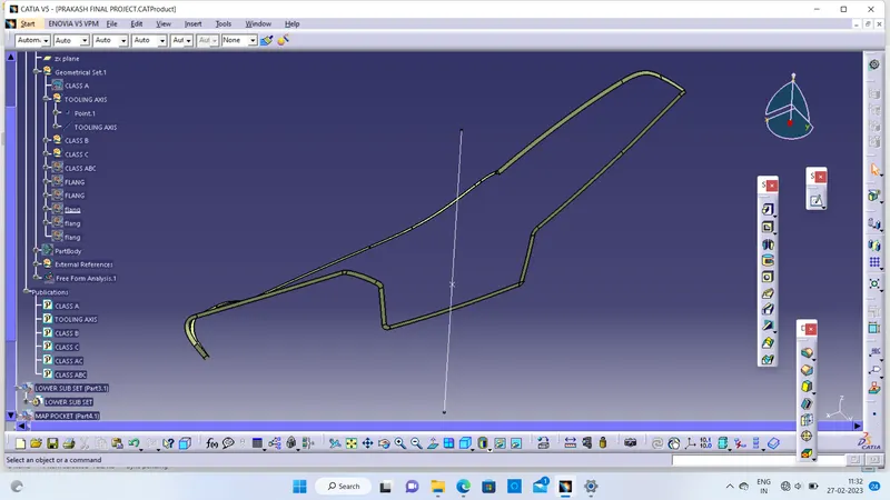
CREATION OF CLASS C
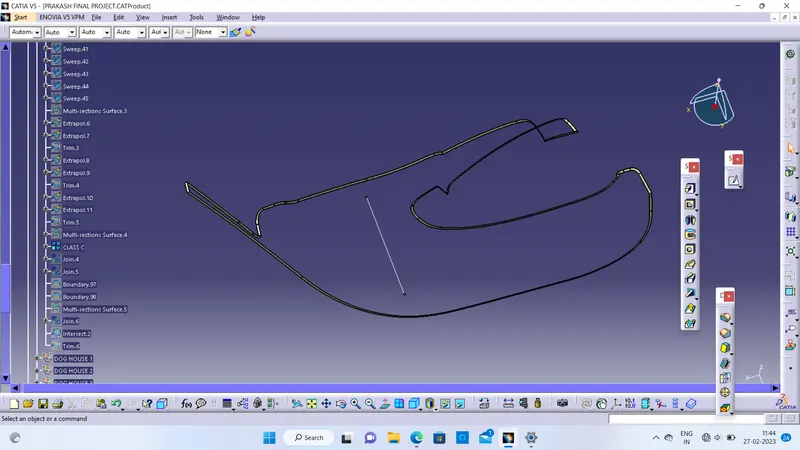
The class C surface is the surface which is created to provide thickness to the class A surface with the help of class B surface.
The class C surface is the middle portion of the class A and class B surfaces.
The class C is created with the help of the sweep command in surface workbench.
The class A surface's boundary is taken as profile (guide curve) and then tooling axis created is taken as direction of the sweep in subtype draft direction
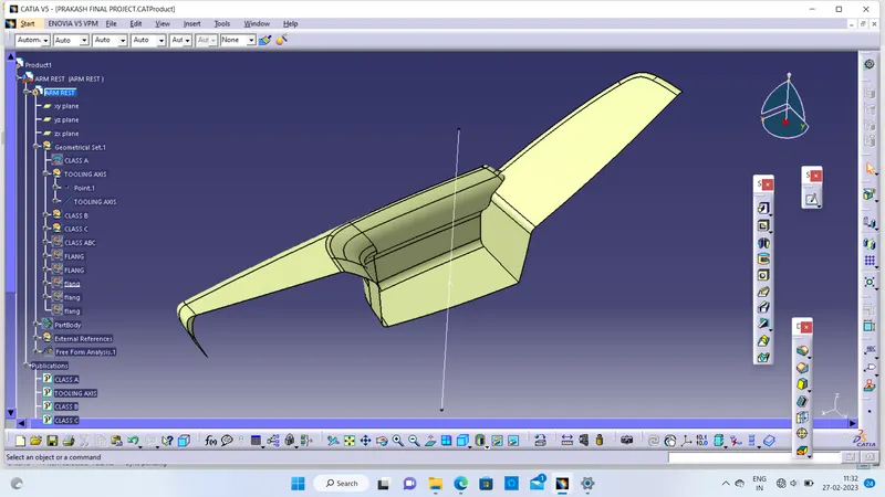
- ARM REST:
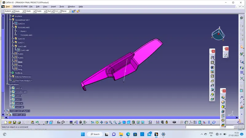
Class A
CLASS B:
CLASS C:
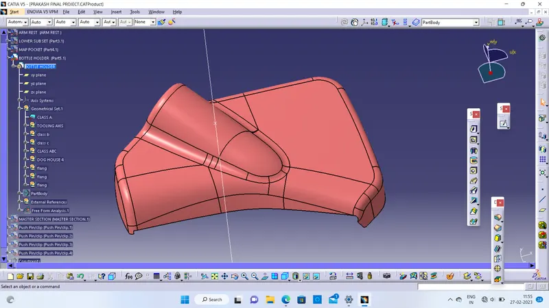
- BOTTLE HOLDER:
CLASS A :
CLASS B :
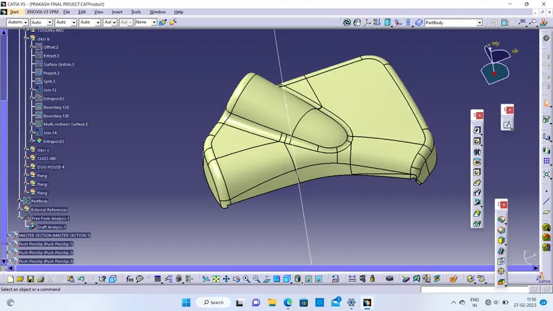
CLASS C :
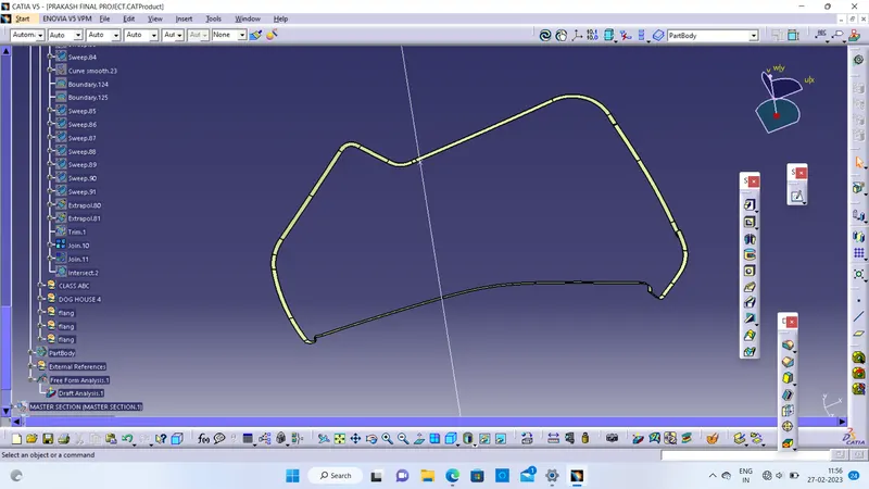
DRAFT ANALYSIS:
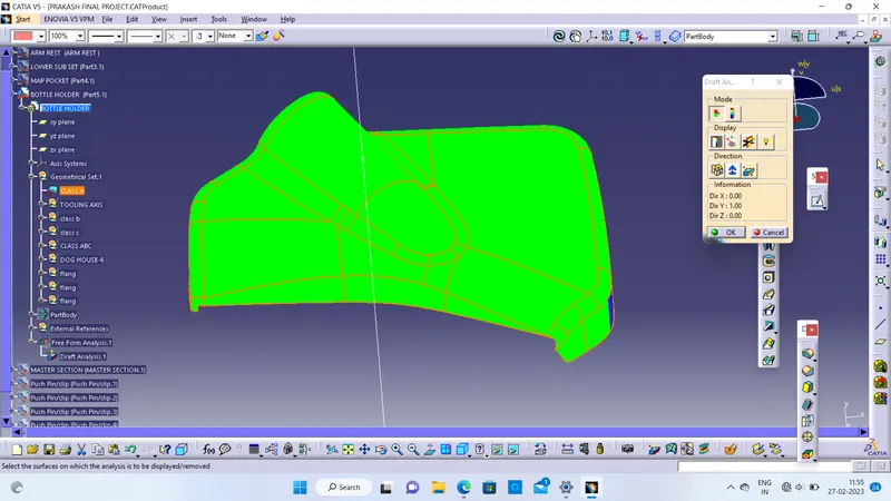
- MAP POCKET
CLASS A
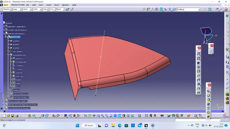
CLASS B
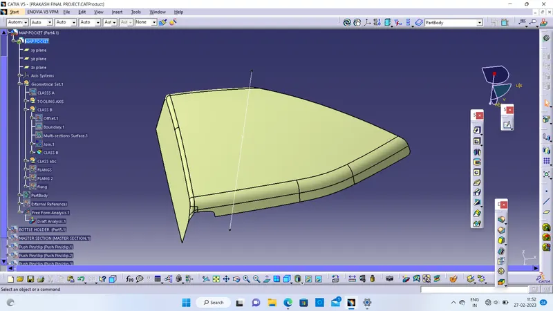
CLASS C
CREATION OF ATTACHMENT FEATURES FOLLOWING THE MASTER SECTION
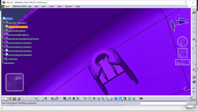
- DOG HOUSE
Dog house is the attachment feature which helps you to assemble things at certain heights and also resolve the plastic defects.
There is plenty dog house design which can be used for assembly purpose but we will be using the one provided to by the resources.
The master section or the engineering drawing must be followed for creating the dog house
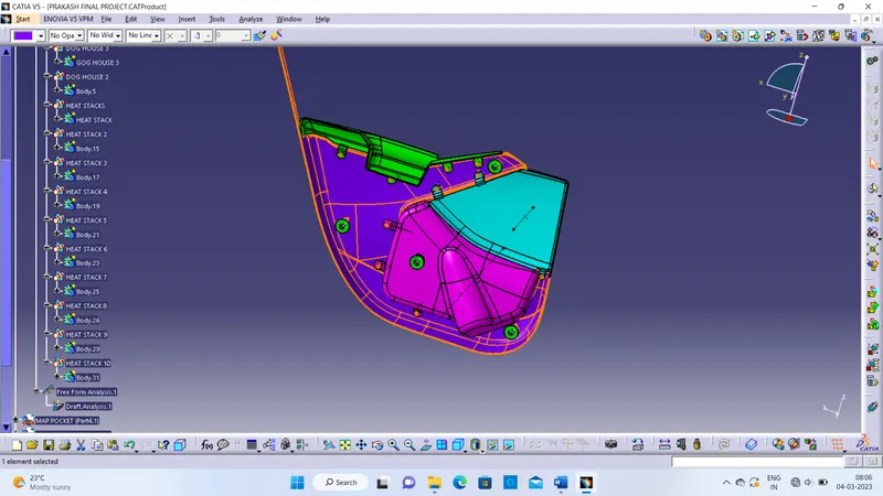
- HEAT STAKES
Heat Staking is a pulsed-heat process to join two or more parts out of which one at least is made of plastic.
The process is to deform the plastic material using heat and force at a set process time.
The bond is made by partially de-forming the plastic part in order to fix the other.
Heat Staking makes it easy to bond metal to plastic and is commonly used in high volume/low-cost applications such as automotive, IT and consumer appliances.
- RIBS
The ribs provide economical stiffness and strength to the part without increasing the overall thickness of the part.
The ribs are used as locating and arresting in the assembly as locators.
Proper alignment in mating parts, slot and rib pair is long lasting other than screw pair which loosen up with time.
thickness, quantity, height, manufacturability and location
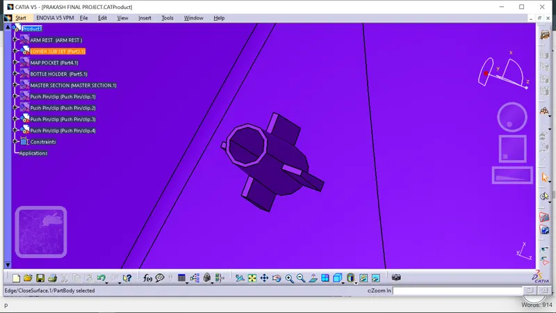
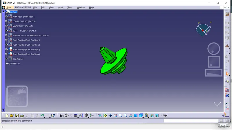
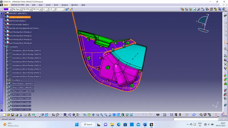
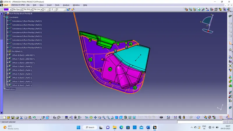
- PUSH PINS
These pins are used for the assembly purpose.
These pins are guided into the sheet metal body.
The pin is assembled over the dog house on one side and other into sheet metal.
- FLANGES ON THE COMPONENT
These flanges will be built on the components for the fitment purpose with lower substrate.
The hole at center will be guided along the heat stakes.
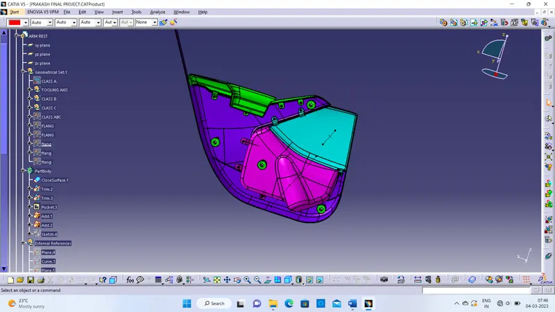
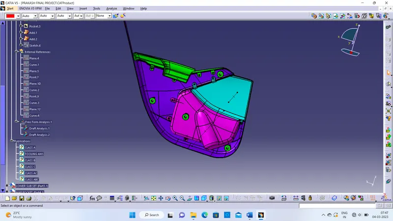
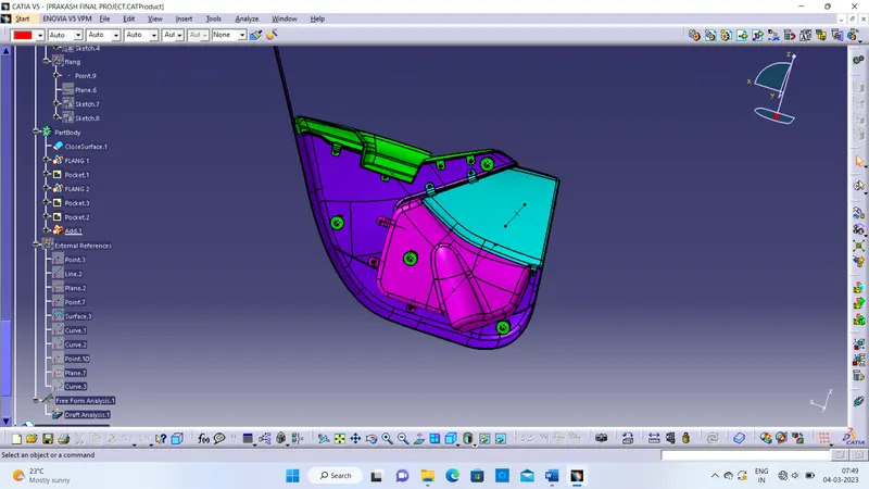
TREE STRUCTURE:
- ARM REST
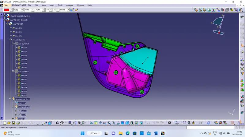
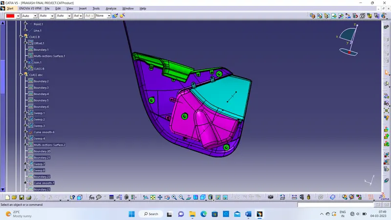
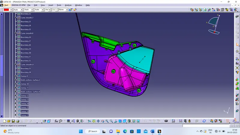
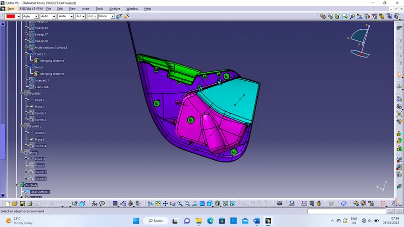
MAP POCKET:
- BOTTLE HOLDER
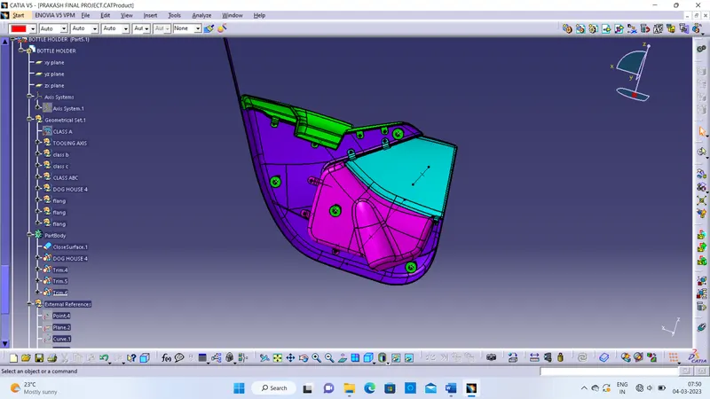
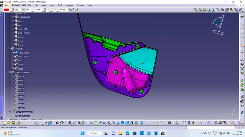
- LOWER SUBSTRATE
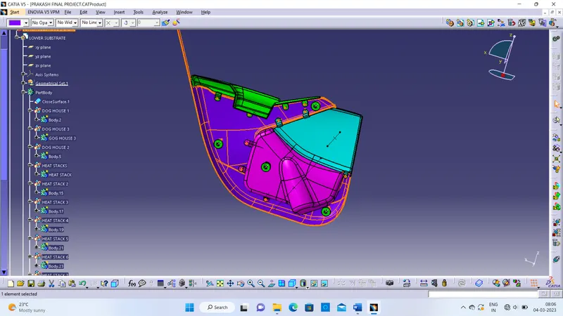
FINAL BODY: