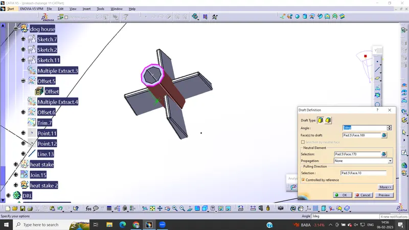
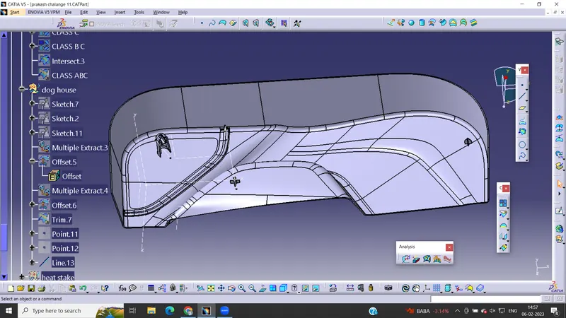
Door Trim Lower with Engineering Features
REPORT :
Step:
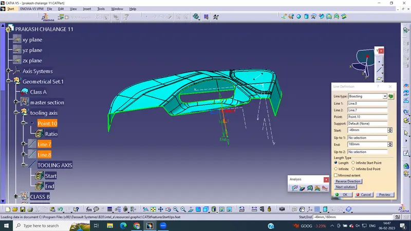
Creating Tooling axis.
Go to insert and select Geometrical set parent and then define the tooling axis.
create a point with the help of point command.
Create a line and make it as axis and chose the direction of the axis as Y -axis.
TOOLING AXIS
1.Class A:
Class A surface are primary used in the automotive environment and rrefer to these surfaces
which are visible to outside world or to the humans..Class A surfaces are those surfaces ,which
are vivible to us (interior/exterior) and have an shape and high surface quality.
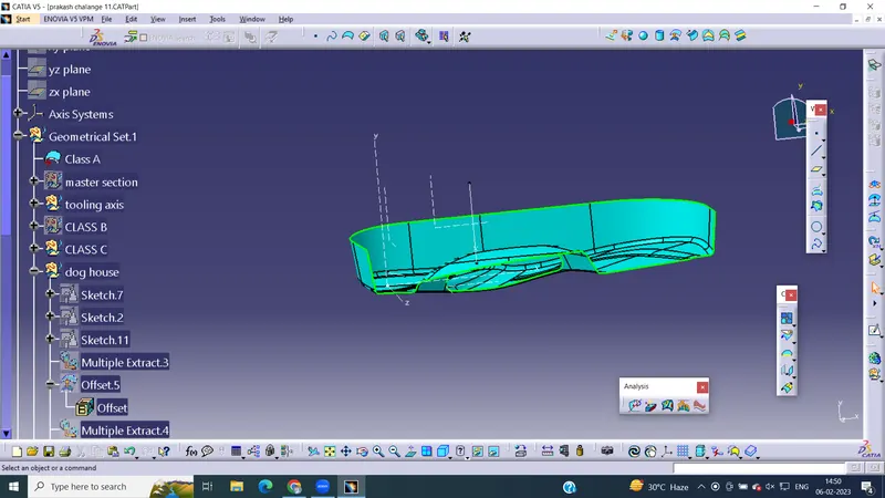
2.Class B:
class B are secondary surfaces that goes fee sometimes ,but are less impoortant sucha s the
inside of your glovebox,ash tray etc., these must be smooth and as well ,but aare not held to the
standard thst class A surface.
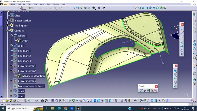
3.Class C:
class C surface is the thickness between the class A and class B ,so there is no need of high end
finishing in class c surfaces.
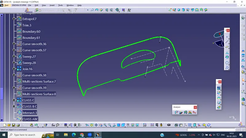
Steps in creating class A ,class B, Class c surfaces:
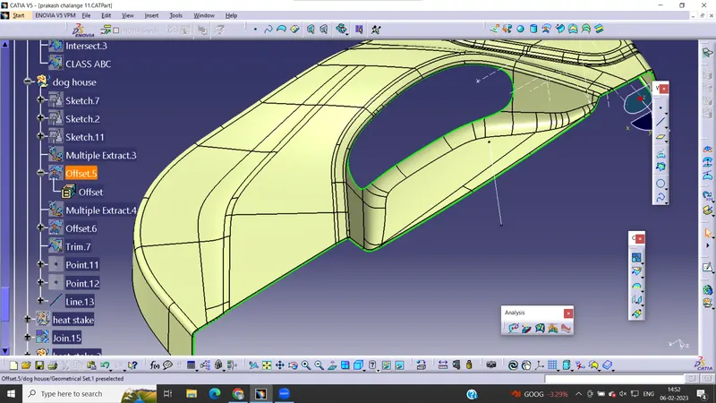
Step:
Publication
Select the CLass A surface - Tooling Axis -click on publication click on yes ,and click on ok.
Step :
Creation of ABC
Click on insert geometrical set AC under input and then click on ok
Define the ABC
Join everything(class A,class C,class B) using join command.
Publish ABC.
Step :
Creation of Close surface: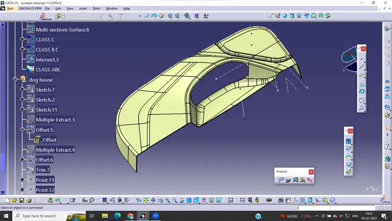
Go to Mechanical Design - Part Body.
Define Part Body and then Select the ABC
Body and Click on CLOSE SURFACE command.
Step:
Perform the solids analysis -2 :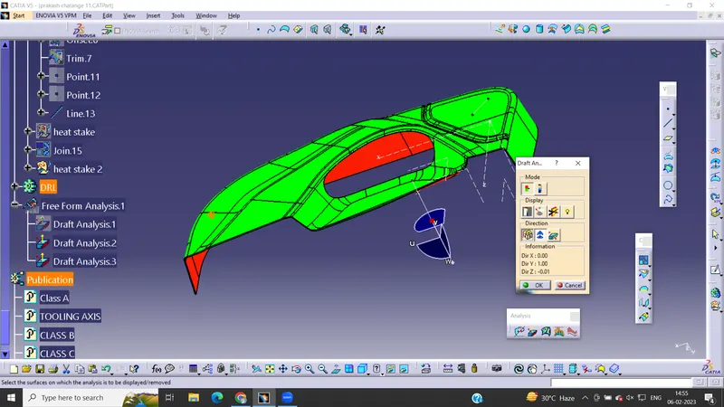
Change the mode of view into materialistic mode Go to insert - click on analysis - feaured draft
analysis.
Drag the mini robot(direciton axis system) on to the axsis that we created.
Click direction symbol and adjust the mini robot on the same axis.
Lock the direction with the help of lock command.
Step 9:
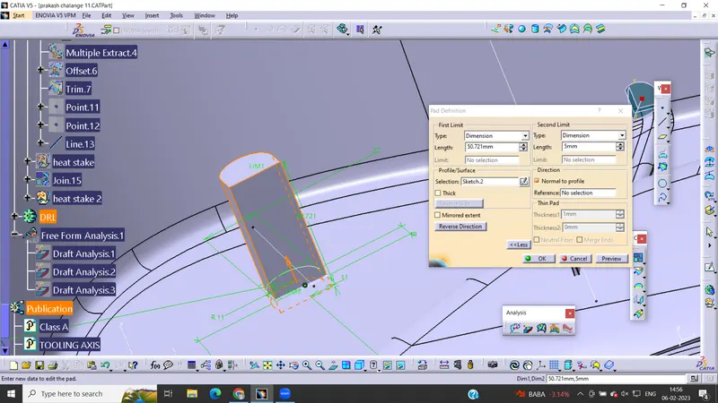
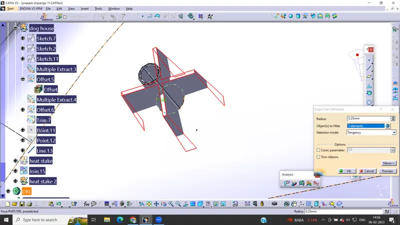
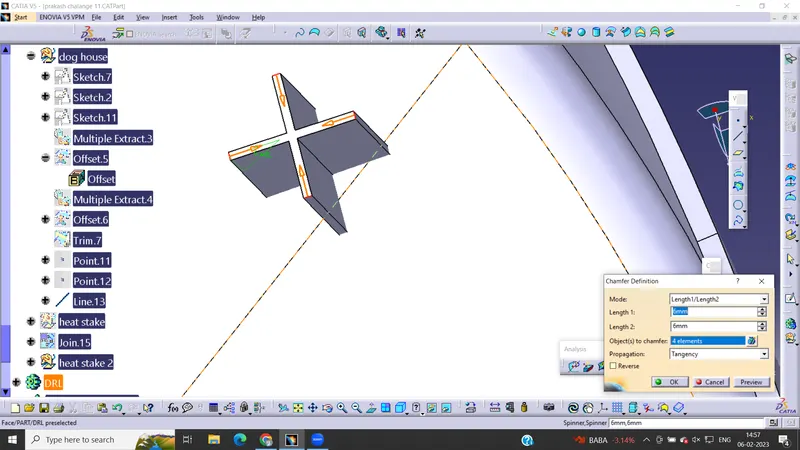
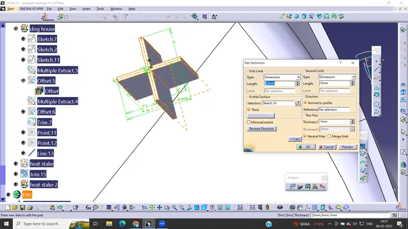
DOG HOUSE