Door Arm Rest Week 8 Challenge
DEVELOP THE DOOR ARM REST AND ITS DRAFT ANALYSIS
AIM -
To create the Door Arm Rest component through the given Class-A surface and at the end performing the draft analysis on the model, also to create the B side and C side features for the Door Arm considering the Design rules.
OBJECTIVES -
To ensure proper tree structure is followed.
Use the close surface feature to make a solid body from the surface
To publish the tooling axis, Class A,B and C surface.
PROCEDURE :-
First Improve the Class A Surface of Door arm rest model In CatiaV5
Check the connectivity of Class A Surface using Boundary option. Ensure that there is no gap between the two surfaces
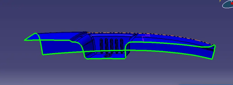
TOOLING AXIS –
Now we need to create the tooling axis for the Door arm rest. Visually check which direction is better for creating tooling Axis in Z –Direction, first create a reference point on any surface as shown in below
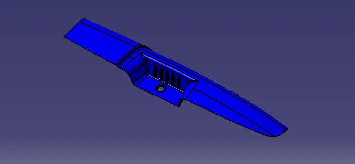
Next creating a reference Axis System on that reference point, by using class A Surface, YZ and XZ plane to creating intersect lines,
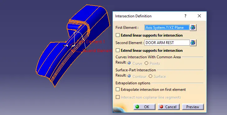
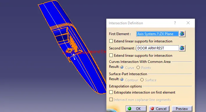
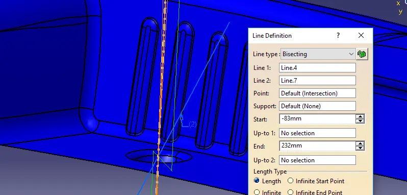
Now using the reference point, create a line normal to the surfaces lines. This line will gives us the Bisector Lines.
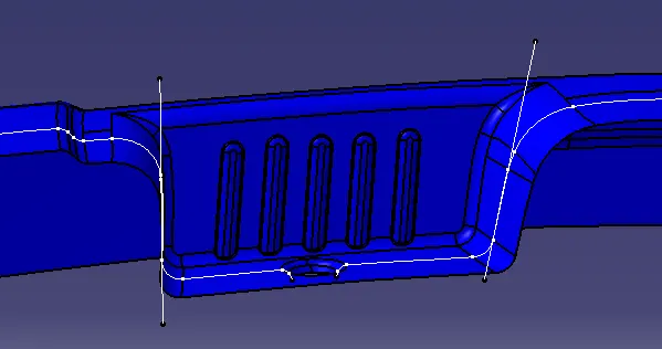
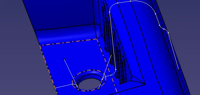
This Bisector lines gives us the Tooling Axis.
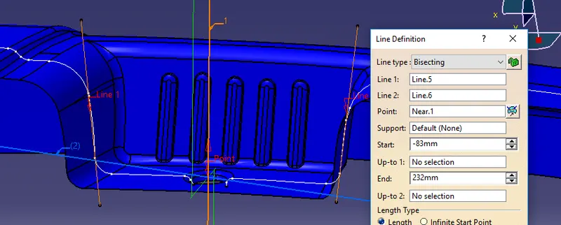
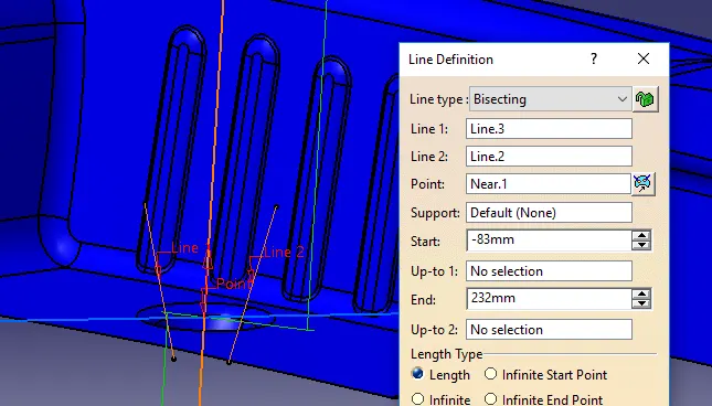
CLASS C SURFACE -
Consider the thickness of the component as 2.5mm.Now we need to create a B surface which will be similar to the A surface at an offset value of 2.5mm
In this operation we are creating a Class B surface in 4 different geometrical sets.
First, we are creating a First half , Scond Half. To create this Surface, we need to extract the class A surface as shown in below
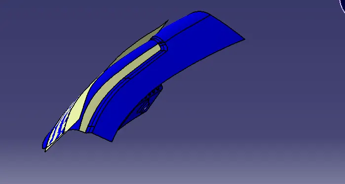
Once the surface is extracted, Untrim it and then extrapolate it by a required value on each side using point continuity. Trim them to form proper walls. Now offset it By 2.5 mm
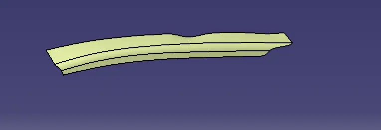
Similarly, we need to extract the Base of the Door arm rest in Different geometrical sets and perform similar operations on its as mentioned above.
Once all the surfaces are created trim these surfaces to form a class B Surface. Given the appropriate fillets to from Class B Surface.
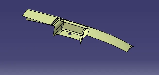
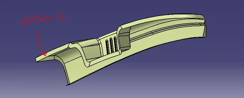
CLASS C SURFACE :-
To create a Class C surface, first extract the boundaries of the Class A surface and extract the adjacent surface to the boundary as shown in the below
Now using the sweep and Multi-sections option create the surface. To perform this operation,
TRIM SURFACES –
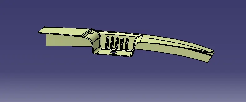
After creation of Class A, class B, Class C surface, we need to trim Class B and class C surface to form a new surface. Then join the trimmed surface with class A Surface to form the final required Surface.
DRAFT ANALYSIS –
The finished part is then analyzed to detect if the drafted part will be easily removed from the injection molding.
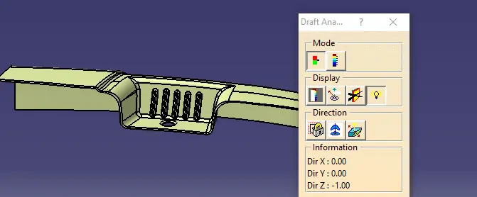
Draft Analysis option in CATIA is enabled through Insert > Analysis > Feature draft Analysis
The Draft analysis Icon has
- Mode
- Display
- Direction
MODE –
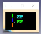
This is the color code that specifies the color to part based on the draft angles and is two types
Quick Analysis
Fully Analysis
The color code Specifications for Switch Bezel Trim are Displayed Below
DISPLAY –
The various Display modes are
Show\Hide color scale
Running point Analysis
Highlight Representations
Light effect
The Display options is used to refine the analysis and results
DIRECTION –
This is one of the important tool which
Compass Definition :- This is used tp pan the compass to the die line or tool direction.
Lock Direction –This option locks the compass at the specified position
Invert Draft Analysis – Which is used to invert the axis System and used to analyze the negative tooling Direction
Draft Analysis Procedure
- The part created has to be changed to material mode in display frame.
- Then by enabling compass definition the axis system is pan along the direction of the part and aligned in line with the tooling direction
- Lock direction is applied that fixes the compass and then the mode dialog box is formed by snapping at any point on the part
- The color codes are classified and Draft angle are applied
Then the ripping point analysis is used to hover around the part to analysis the peramisible draft angle and Analysis is Saved
Class C surface Draft Analysis -
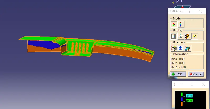
SOLID PART DRAFT ANALYSIS -
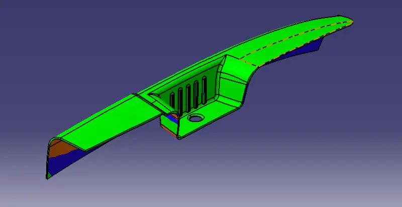
SLIDER LINK -
Using the analysis option, we can perform the draft analysis on class A surface and final part body of Door arm Rest.
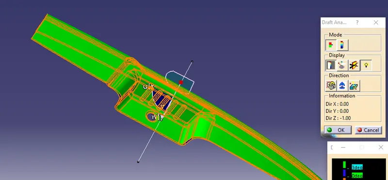
The Green Color is drafted walls of the Switch Bezel are above 3 degree
The Blue Color is drafted walls from 0-3 degree
The Red color Surface are negative Surface
The analysis shows the drafted walls of the switch bezel are above the part of 3 degree which is permissible to manufacture in the injection molding
The Running Point analysis Hovered along the drafted walls show parts are above 3 and will be easily cleared from ejection.
The areas in Negative Tooling that falls short to the permissible design Rules are Shown below
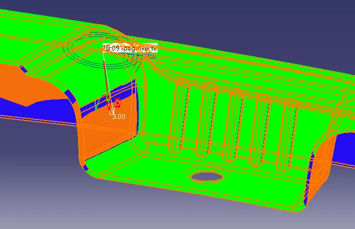
The Class A Surface input needs to resurfaced which needs approved from the Styling Team This Negative Tooling may cause Core And Cavity \Mold Removal
CONCLUSION –
Door arm Rest component using Class A surface have been successfully created and draft analysis have also been performed for the same.