Door Arm Rest Week 8 Challenge
DOOR ARMREST
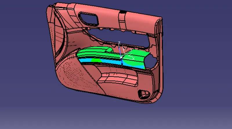
AIM: CREATION OF DOOR ARMREST AND ADD THICKNESS OF 2.5 mm
In an automotive context, an armrest (or arm
rest) is a feature found in many modern
vehicles on which occupants
can rest their arms.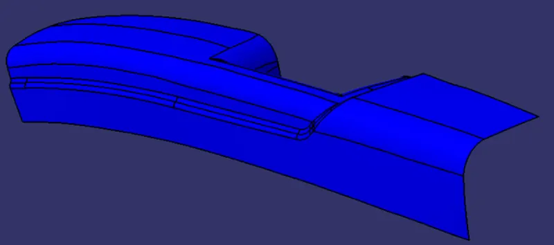
• First, we will extract the base surface of class 'A' and on that create the point and then create Axis system at that point.
• As we have only three sidewalls, we need to create a tooling axis with a different method.
• Then creating intersection curves in the X direction and creating sidelines on that curves and then creating the bisecting line in the sketcher.
• Then creating intersection curves in the Y direction and creating sidelines on that curves and here we have only one side wall so we will create a line passing through the point which we have created in the above steps at an angle of a draft in sketcher. Here angle taken is 5 degree to get all faces feasible with tooling direction.
Then create a bisecting line through X and Y direction tooling lines.
• After that create the dummy tooling axis in the Z direction.
• This line is the Dummy tooling axis for our part.
• It is the direction in which the component will be ejecting after the molding process is completed.
• The direction of the tooling axis should clear the maximum portion of the part.
• It should be selected in such a way that number of side cores will be minimum
as it will add more cost to the process.
Workbench and tools used
Generative shape design
• Extract
Extrapolate
• Join
• Trim
• Offset
Boundary
Edge fillet
• Intersection
Sweep
• Close surface
• Feature Draft Analysis
Design Process in CATIA V5
Given Data,
Class A surface.
Tooling Axis creation: Bisecting Method
• First, we will extract the base surface of class 'A' and on that create the point and then create the Axis system at that point.
• As we have only three sidewalls, we need to create a tooling axis with a different method.
• Then creating intersection curves in the X direction and creating sidelines on that curves and then creating the bisecting line in the sketcher.
• Then create intersection curves in the Y direction and create side lines on that curves here we have only one side wall so we will create a line passing through the point which we have created in the above steps at an angle of the draft in the sketcher. Here angle taken is 5 degree to get all faces feasible with tooling direction.
• Then creating bisecting line through X and Y direction tooling lines.
• After that create the dummy tooling axis in the Z direction. • This line is the Dummy tooling axis for
our part.
Compass Method:
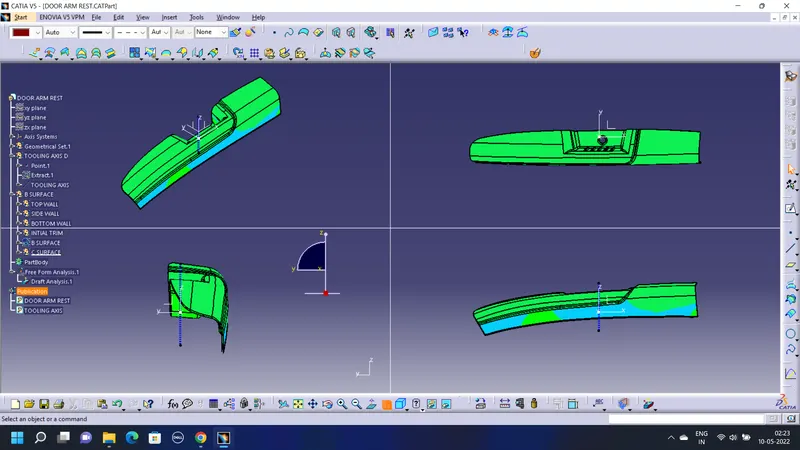
Checking draft analysis with dummy tooling axis and if tooling axis is not correct then adjusting compass to get the surfaces as green.
Then right-click - lock current orientation - cancle draft analysis - select line - line direction - compass direction.
Then View - Reset compass
This line will be the Main tooling axis.
Creating Different tooling axis for Cavity and Adjusting with compass then creating a line with compass direction in Y-direction which is for Slider.
Tooling Axis for side core:
Create the line in X-direction for side cores.
'B' Surface Creation:
• Extract Class 'A' Surface.
• Untrim extracted surfaces.
Extrapolate to some extent.
• Use the trim and select the proper surface.
• Offset inward at 2.5 mm
• Use edge fillet.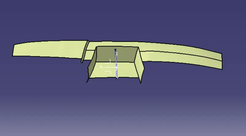
'C' Surface Creation:
'C' Surface Creation:
• Take outer boundary using Boundary
command of class 'A' surface
• Use a Smooth curve.
• Use sweep command to create a surface using tooling axis and draft angle as 3 degrees.
• Create points and lines to split the
surfaces as and where ever needed • Join the split surfaces with the multi-section surfaces.
Final Body creation: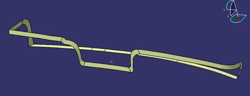
• Join class 'A' surface and 'C' surface.
• Trim resulting surface with 'B' surface.
Join the surface.
• Result is complete close surface.
Final Body creation:
• Join class 'A' surface and 'C' surface.
• Trim resulting surface with 'B' surface.
• Join the surface.
• Result is complete close surface.
Solid Body:
Change to Part workbench.
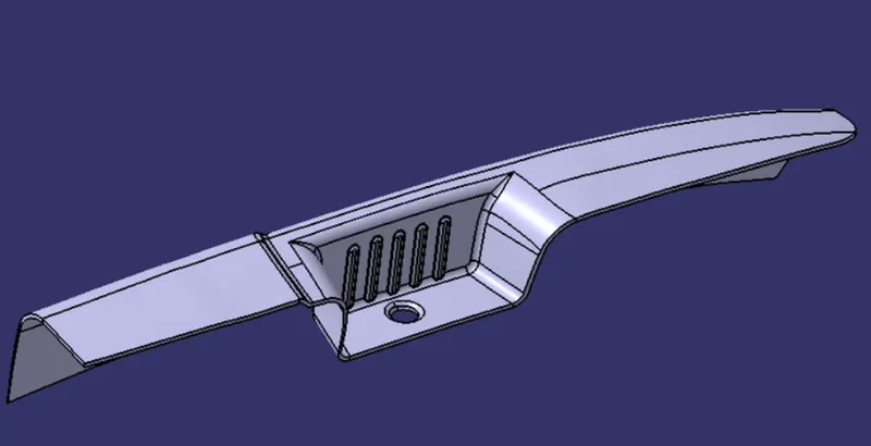
• Create Body.
• Surface Base Feature Close surface - select last join.
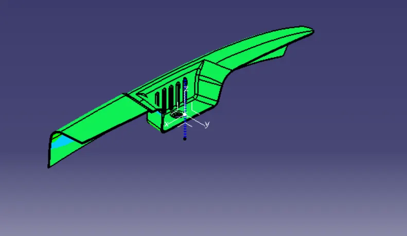
Final Draft Analysis: