Door Arm Rest Week 8 Challenge
AIM:
To Create the Class B and Class C surfaces form the given class A surface of the door arm rest and to Draft analysis the surface of the given model.
PROCEDURES:
CREATE TOOLING AXIS:
Check for any kind of surface openings using the boundary feature. Fix the open surfaces if any.
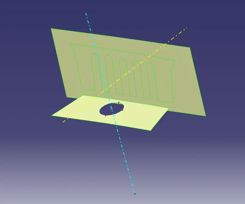
Create two tooling axes for the component as shown below.
Extract the surfaces from which the tooling axis is to be passed. Create a point exactly at the centre of the extracted surfaces.Create a random line from the point perpendicular to the extracted surface for both base and side face.
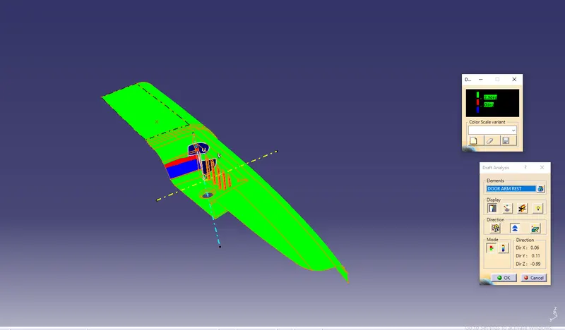
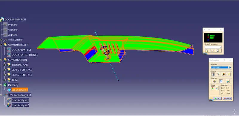
Check for the draft analysis by fixing the axis to the line created and click on the surfaces.
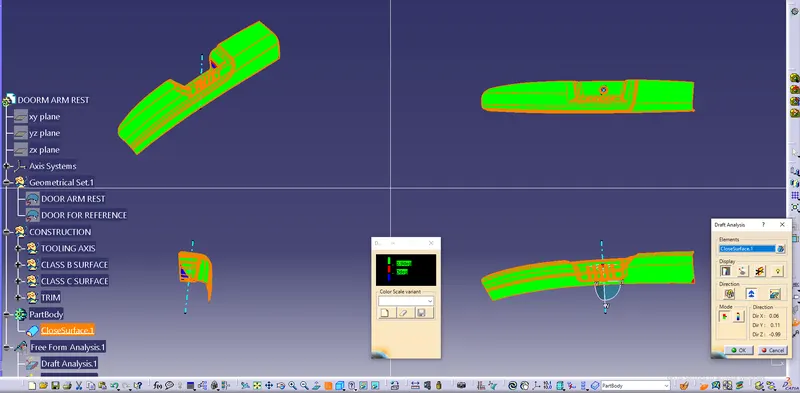
The surface will be hilited in green, blue and red colours. The green colour is to be hilited on the top view, sides with blue and red for the bottom of the surface. Adjust the axis such that the green colour is hilited totally from the top view. After adjusting the axis adjust the angle of the created line as per the adjusted axis.
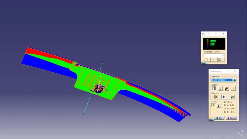
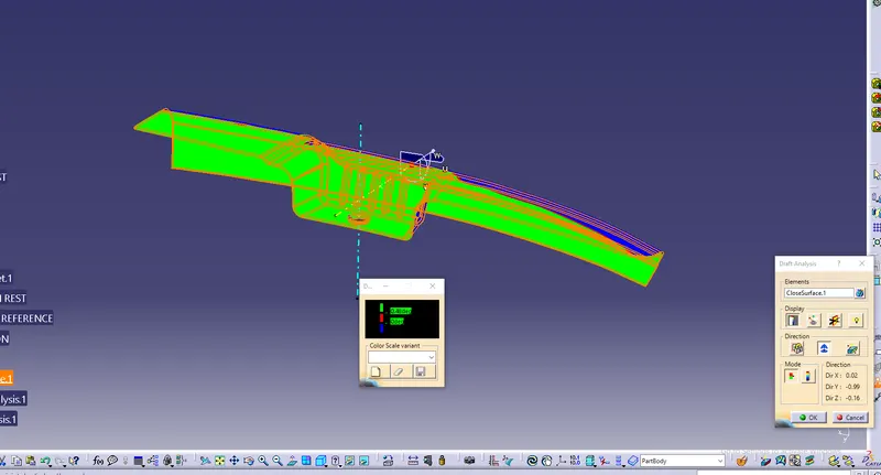
The adjusted line will be the tooling axis. Similarly, adjust the second tooling axis as done for the first one and draft analysis for slider axis for the creation of side core.
CLASS B SURFACE:
After creating the tooling axis, create a Class B surface from the class a surface.
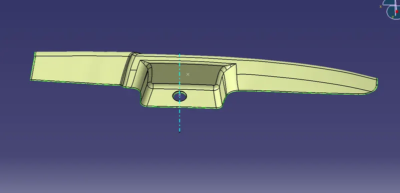
Extract the surfaces from the Class A surface,Offset to 2.5 mm such that maintaining the thickness as mentioned. Patch the B surface which offsetted part using tool such as multisectio and fill option.
The above class B surface process is to be done part by part for tooling process.
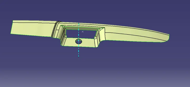
The Class B surface which patched rom offset of class A surface.
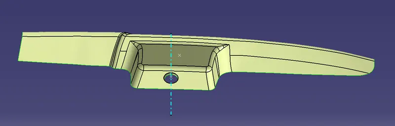
After creating B surface extrapolate the all the edges for 3 mm.
CLASS C SURFACE:
After creating the class B surface, class C surface is to be created form the class A. Class C surface is the side surface of the solid component.
Create a boundary line on the edges of the class A surface.The extracted boundary lines are sweeped, setting the created boundary lines as guide curves and the tool axis as the draft direction. The angle of sweep is given as 3 degrees so that the component is acceptable for the draft analysis.After creating the total class C surfaces, join the surfaces so that no openings are created on the surface.
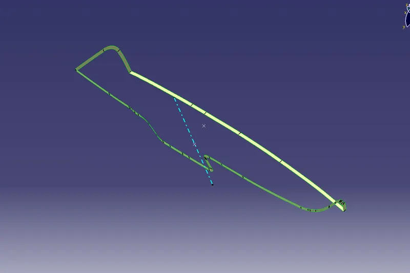
JOIN CLASS A,B AND C SURFACES:
Join the class A and C surfaces and trimmed surface with class B surface. Chick the component such that no surface opening are formed.
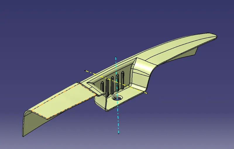
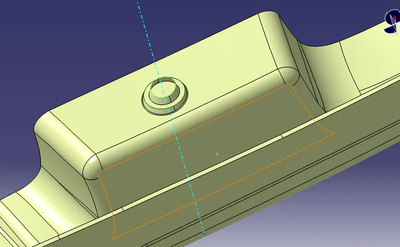
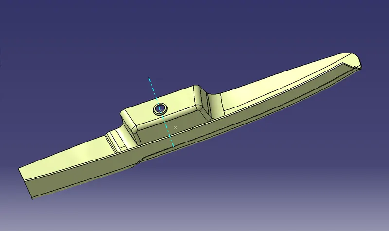
Finally trimmed the cub holder surface and create a closed surface
SOLID MODEL:
Create a solid door arm rest with using tool closesurface in the part workbench.
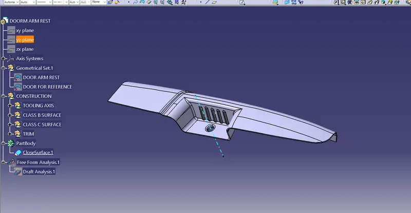
Isometric view of Door Arm Rest:
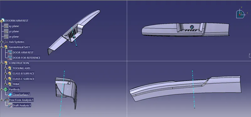
DRAFT ANALYSIS:
Draft analysis is to be done for the solid component with the tooling axes. Place the axes on the tooling axis as done for the class A surface and analyze the component. The draft analysis on both tooling axes is as shown below.
CONCLUSION:
Therefore, Created the Plastic design for Door Arm Rest and added thickness to it and generated the Draft Analysis on a solid surface for Door ArmRest.