Door Arm Rest Week 8 Challenge
DOOR ARM REST
Aim: Creation of door arm rest with thickness of 2.5 and perform the draft analysis.
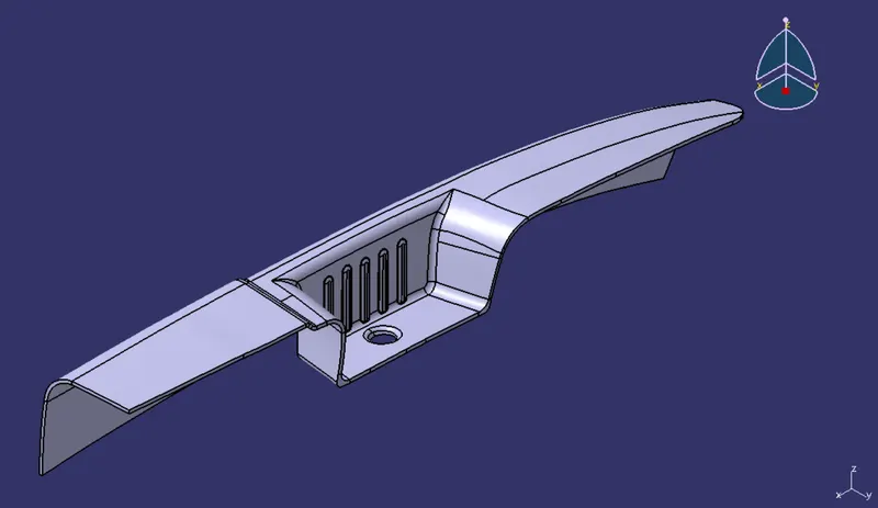
Tooling Axis
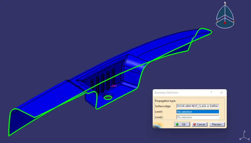
First we check weather the class-A surface is fully joined using boundary definition tool. We can see a continuous border on the outer edges only.
We then extracted the bottom surface and untrimmed it so that it can be used as a surface reference to create the Z-axis tooling direction. The Z-axis visually clears most of the surfaces, the other surfaces and exspeaciouly the ribs are cleared using side cores which requires an tooling axis of its own.
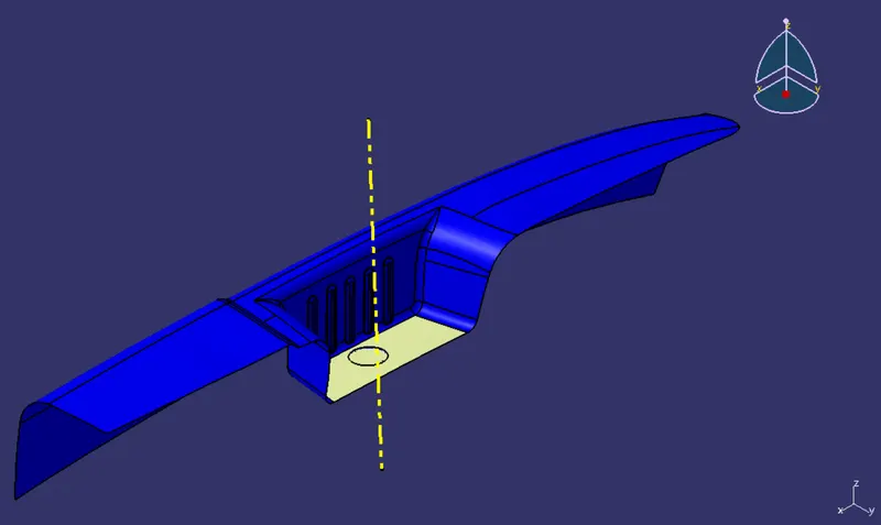
The side core tooling axis is ideal in the Y-axis, so the side surface which is perpendicular to the ribs is extracted and untrimmed so to create a normal to the surface line which is our side core tooling axis.
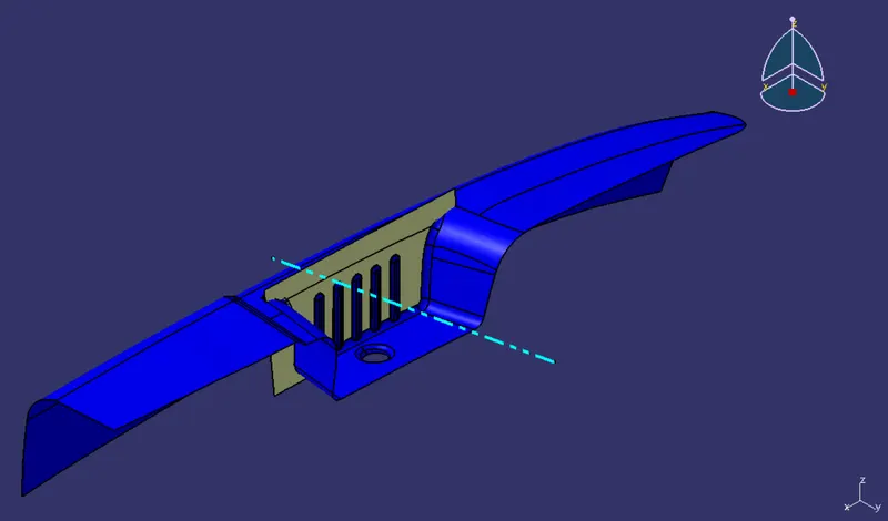
Below represents both the tooling axises in the Z & Y direction. The yellow is the normal tooling axis and the blue line is the side core tooling axis.
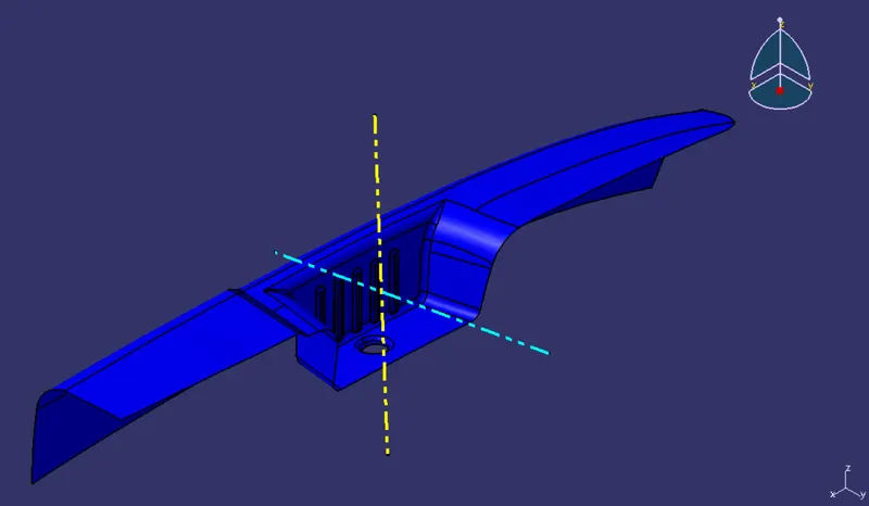
Class B-Surface
An offseted surface is created using class-A surface as reference. Offset=2.5 mm
Tools Used
- Extract
- Multiple Extract
- Offset
- Join
- Extrapolate
- Trim
- Split
- Boundary
- Edge Fillet
- Sweep
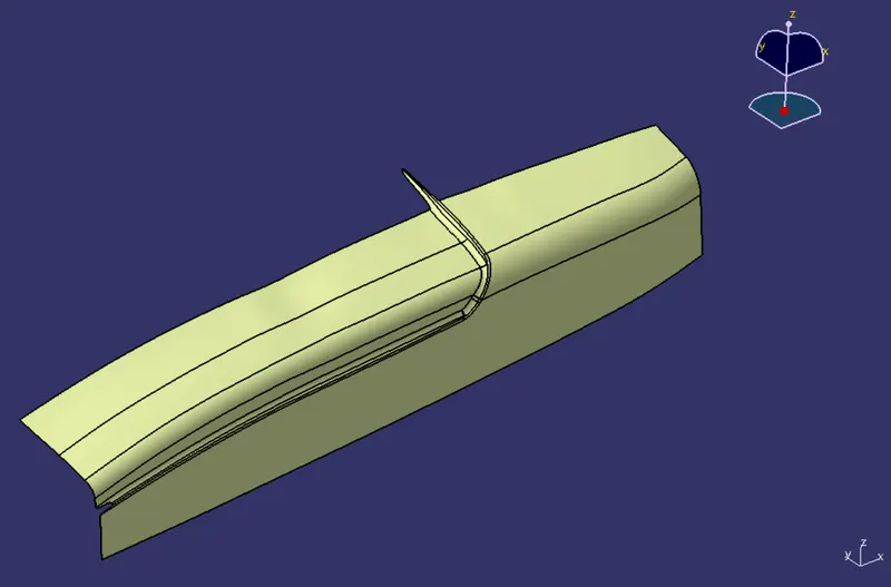
The wall surfaces are created seperately so that it could easly trimmed off from the the above offseted surface.
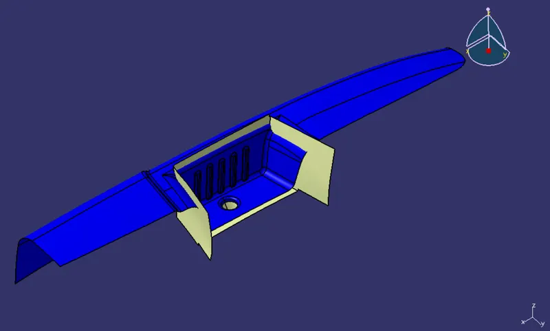
The required fillet is given after reducing the class-A surface fillet radiuses with the thickness.
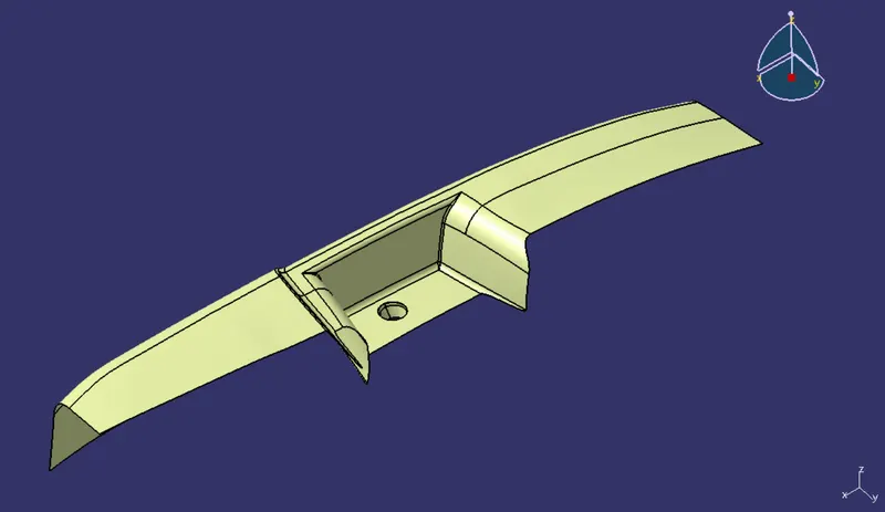
Class-C Surface
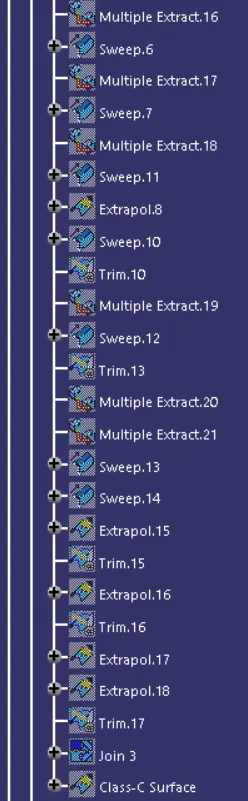
The boundaries of the class-A surface is extracted so to create a sweep with reference with the draft tooling axies. The draft angle is given as 3 degrees.
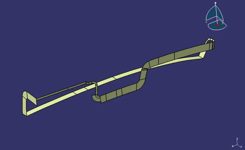
The class-A and class-C is joined and the join is trimmed with the class-C surface.
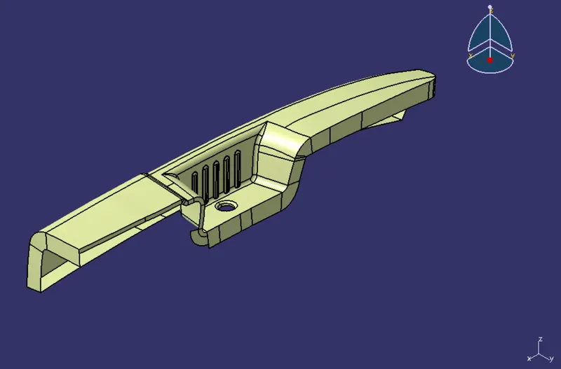
Check weather the surface is closed or not using the boundary definition tool. The tool will not work if the surface is closed, it will show an error.
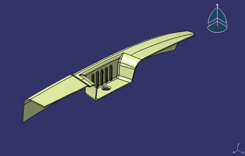
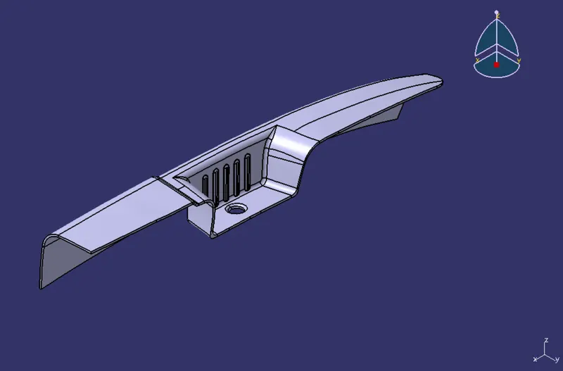
Using part body workbench the the surface is converted to a solid using close surface tool. The below is the part body that we after hideing the above surface.
Draft Analysis
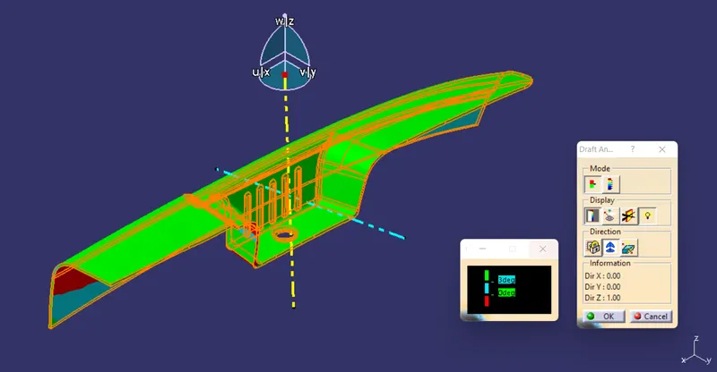
The below figure shows the draft analysis for the tooling axis in the Z-direction. We can see it clears most of the surfaces.
The four views of the above shows that a wall is not cleared.
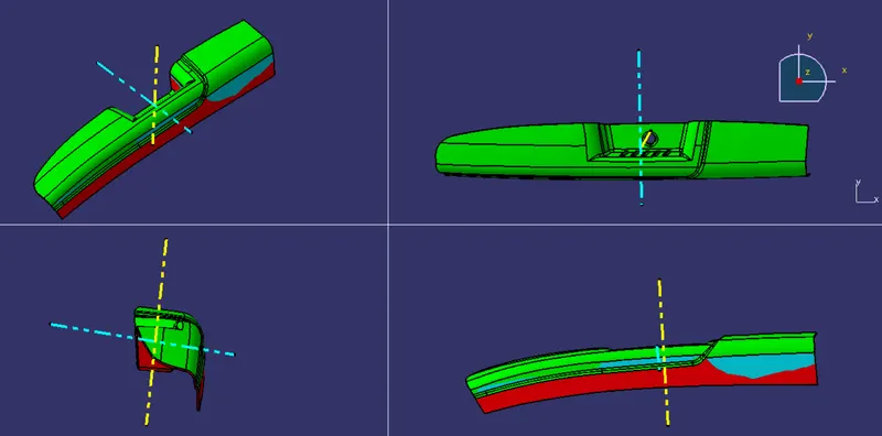
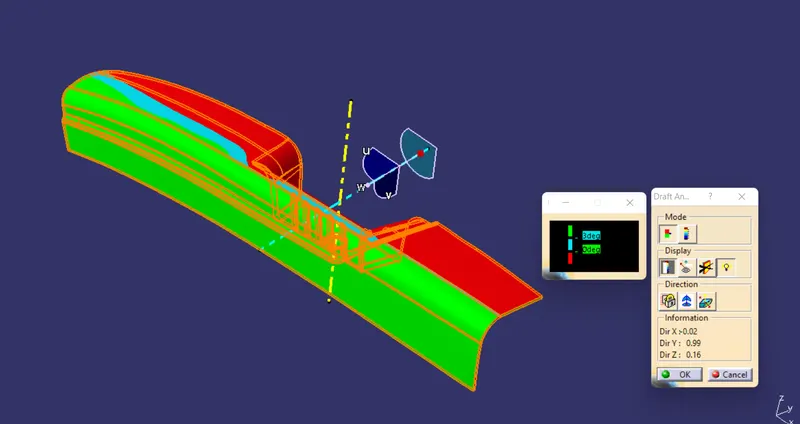
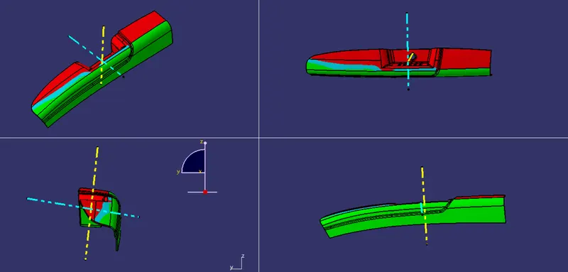
This the draft analysis done for the tooling axis in the Y-direction. Here the walls are all cleared,
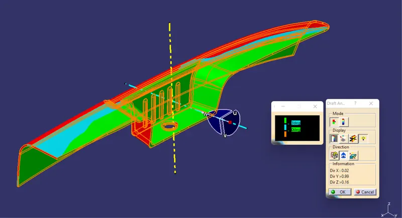
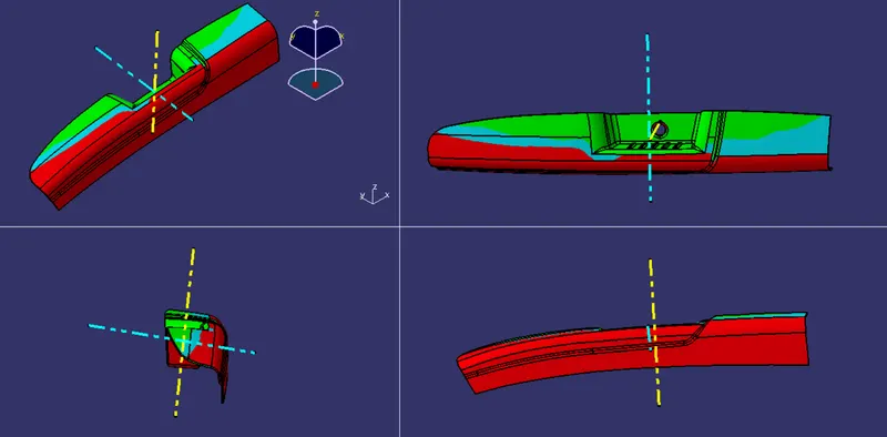
The Y-direction draft is reversed so that the other side surfaces could be cleared. In practical there would be side cores in the other direction which will slide in and out of the mold cavity forr easy uninterupted release of the coponent.
Isometric View
Front View
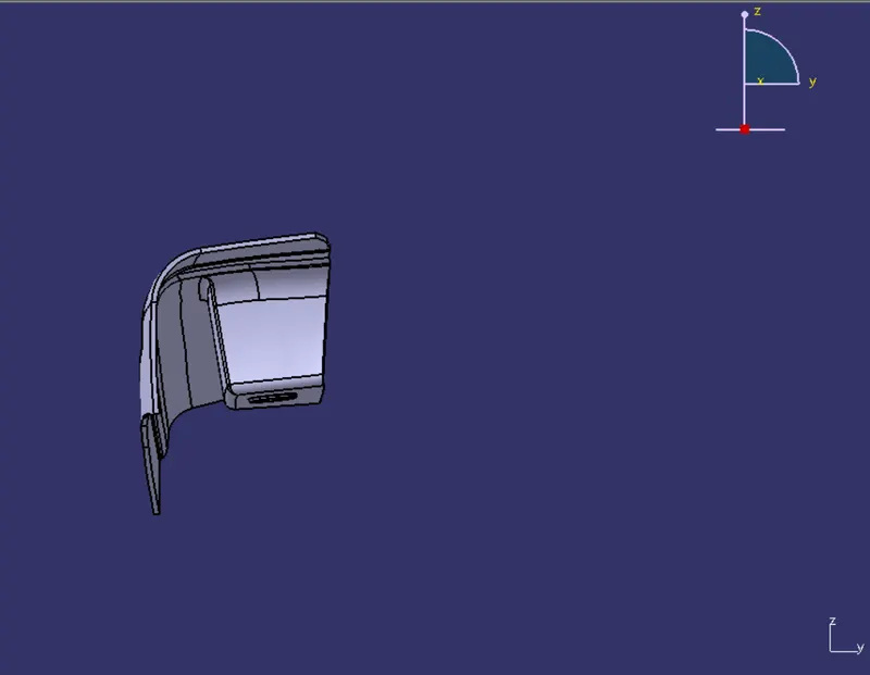
Left Side View
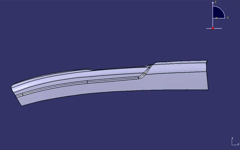
Right Side View
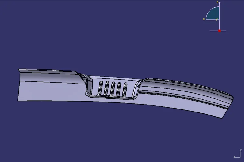
Top View
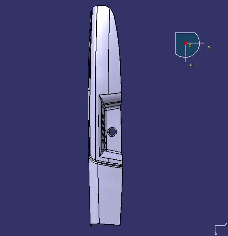
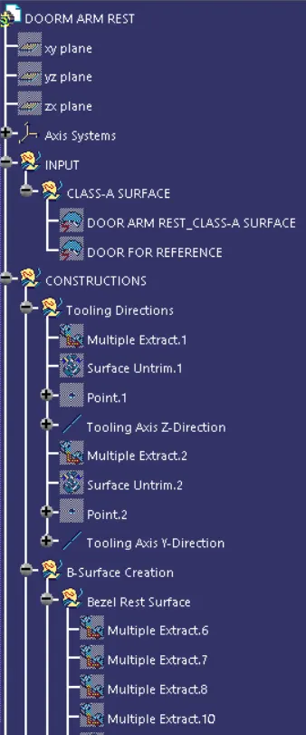
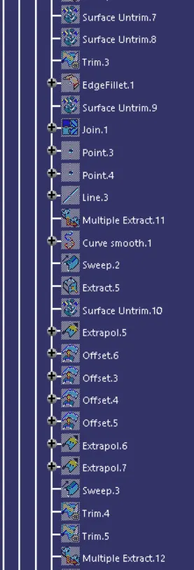
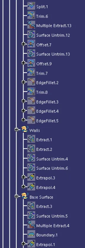
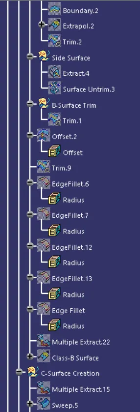
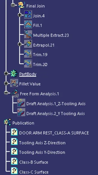
Feature Tree & Publications