Door Arm Rest Week 8 Challenge
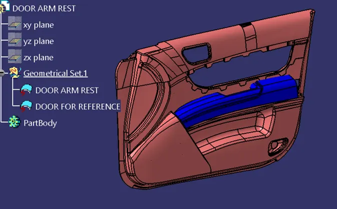
DOOR ARM REST
AIM:
To create the door arm rest with the given thickness of 2.5mm And generate the draft analysis report forvthe closed body
PROCEDURE:
- Since the class A part is already with you all we need to create is A class B surface
- now as we have both the Class A and Class b surface we can create the Class c using the swept option by Creating the boundary over the class A surface with respect to the tooling direction or what ever needed
- In this case as we have the door arm rest,We can make sure that the door arm rest is also having back surface,It is difficult to create the swept along it.So the swept is created using the referance surface for the back surface.
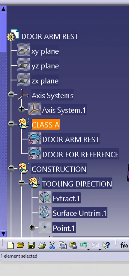
TOOLING DIRECTION
- The tooling direction is basicallky the direction that the mold pulls apart.the mold is built in two seperate pieces basically you have a cavity side and you have the core side.The core pulls apart from the cavity and thats the dyeline or the tooling Direction
- To create the tooling direction from the class A surface choose the appropriate plane and create a line normal to the surface
- To maker sure that the line created is Tooling axis,view the tooling axis in a normal view.If we can see the whole class A with no blind spots,we can say that the created line is the tooling direction or the DYELINE.
CREATING THE CLASS B SURFACE
- A Class B surface is a surface which is not sceen for it accomodates the fits and fixtures on it.In other words we can also say that the class B surface is a other side of the class A surface.
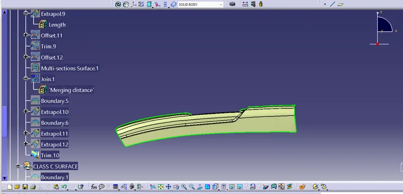
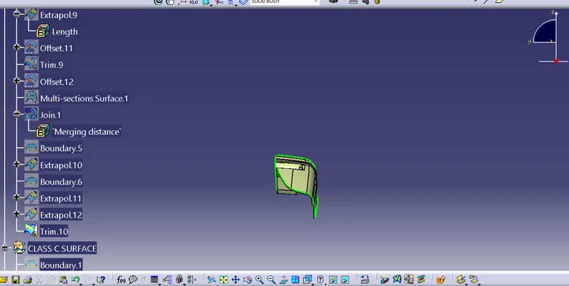
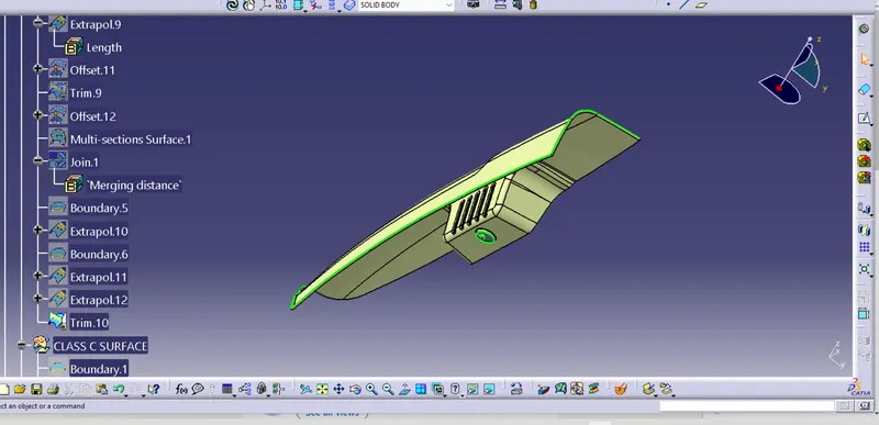
- As the designer states the thickness,we create the class B surface by offsetting the required surfaces from the class a surface
- Creating different geometrical sets for different parts while creating the class b surface so that we be able to identify or editr in future if required.Also give appropiate names so that they could be easily identified
- Extract what ever needed from the Class A surface and offset them for the required thickness and extrapolate it required
- Using trim,split and other different options and approprite techniques we aquire the required output as class B surface
- Make sure to join them
CREATING THE CLASS C SURFACE
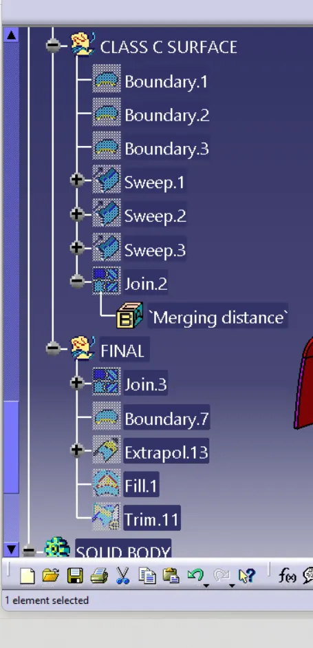
- Swept is option we use to combine the class A and class B.The surface we create from class A is class C surface
- Visually the class C surface is the surface which has been created from the boundary of the class A
- Now by using the Swept option which indeed has the draft direction option is been used and a draft angle of 3 degrees is been given
- The resulting surface is class C surface
- The class C surface and Class A surface are joinede and then trimmed with Class B to produce the required output.
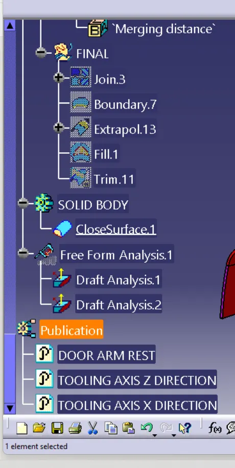
A closed body will be created from the output which has to further deal with draft analysis
DRAFT ANALYSIS:
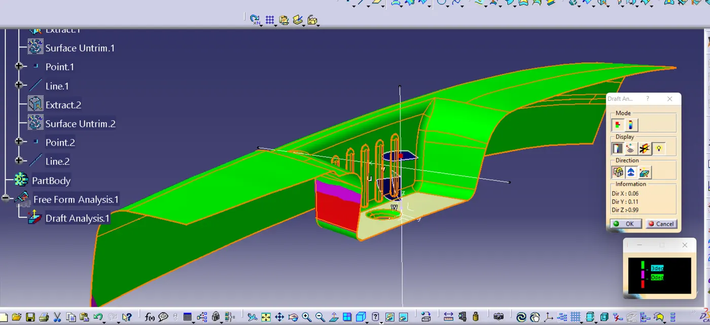
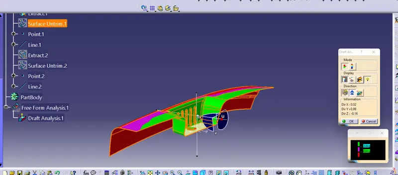
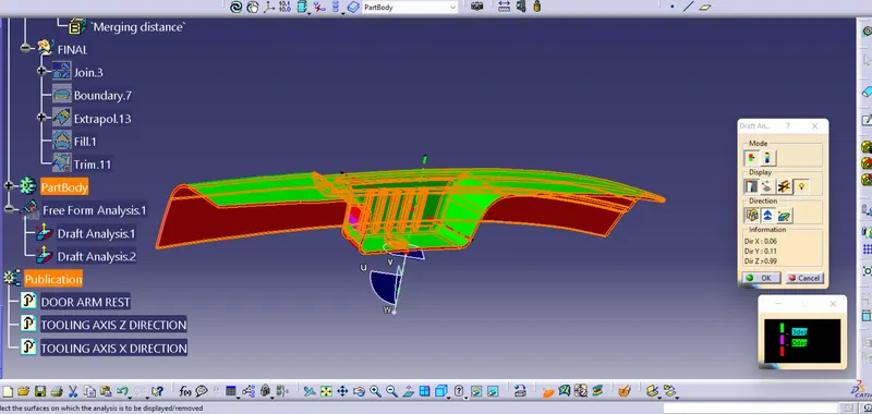
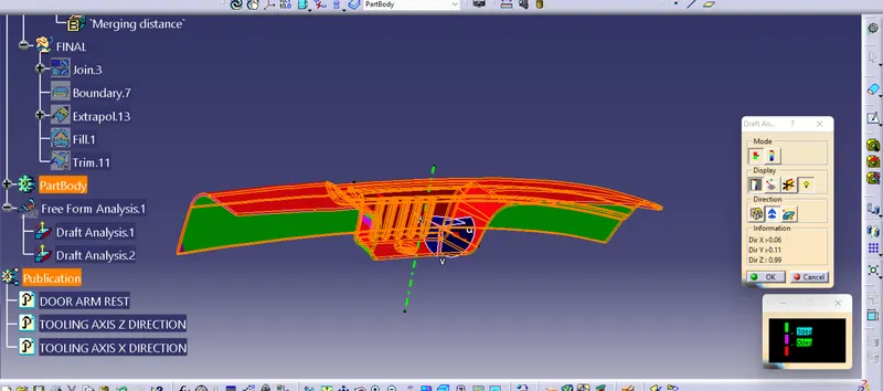
- The Draft Analysis command enables you to detect if the part you drafted will be easily removed.This type of analysis is performed based on color ranges identifying zones on the analyzed element where the deviation from the draft direction at any point crrespondings to specified values.
RESULT:
Created the plastic design for DOOR ARM REST and added thickness to it and generated the DRAFT ANALYSIS on a solid surface for DOOR ARM REST.
CLASS A SURFACE
DRAFT ANALYSIS
IN TOOLING DIRECTION
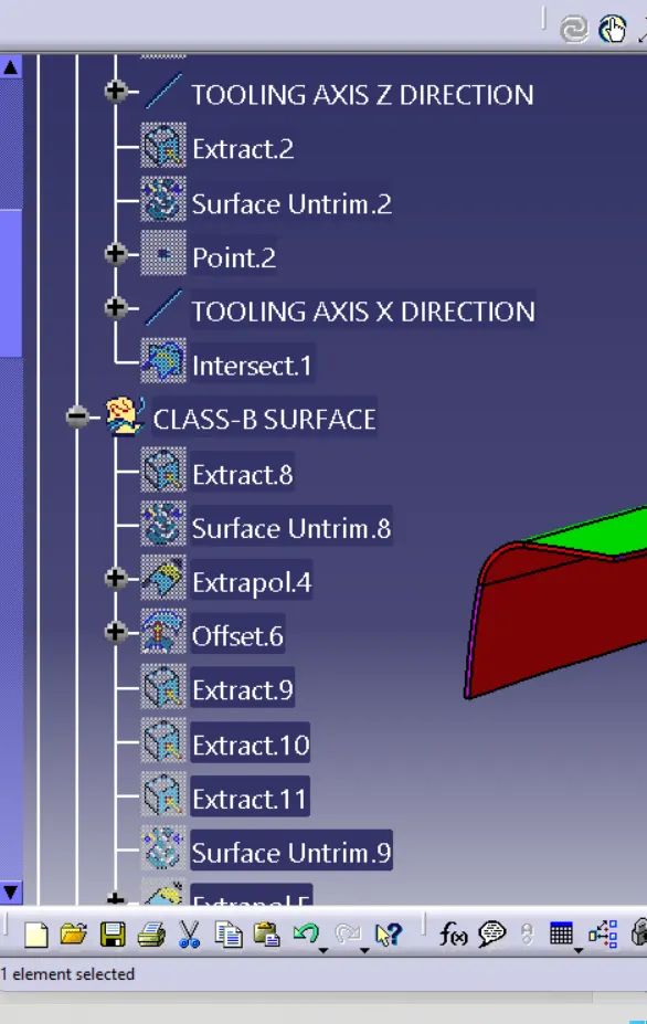
CREATING THE CLASS B SURFACE
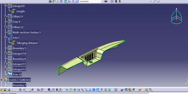
CLASS C SURFACE
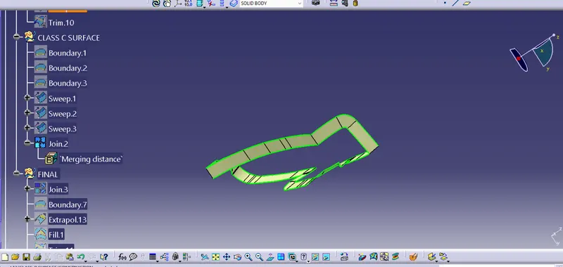
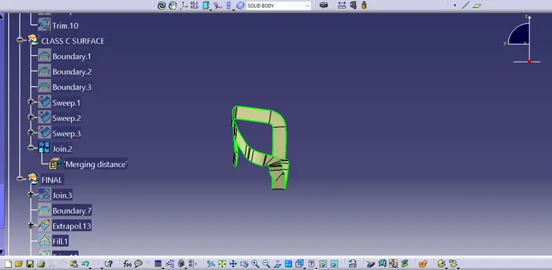
FINAL JOINING SURFACE
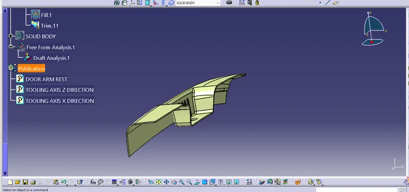
CLOSED SUEFACE
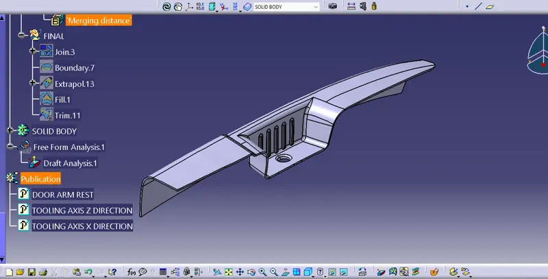
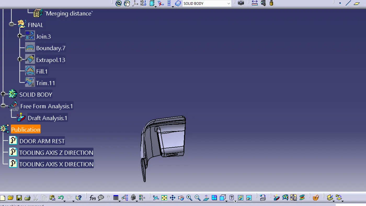
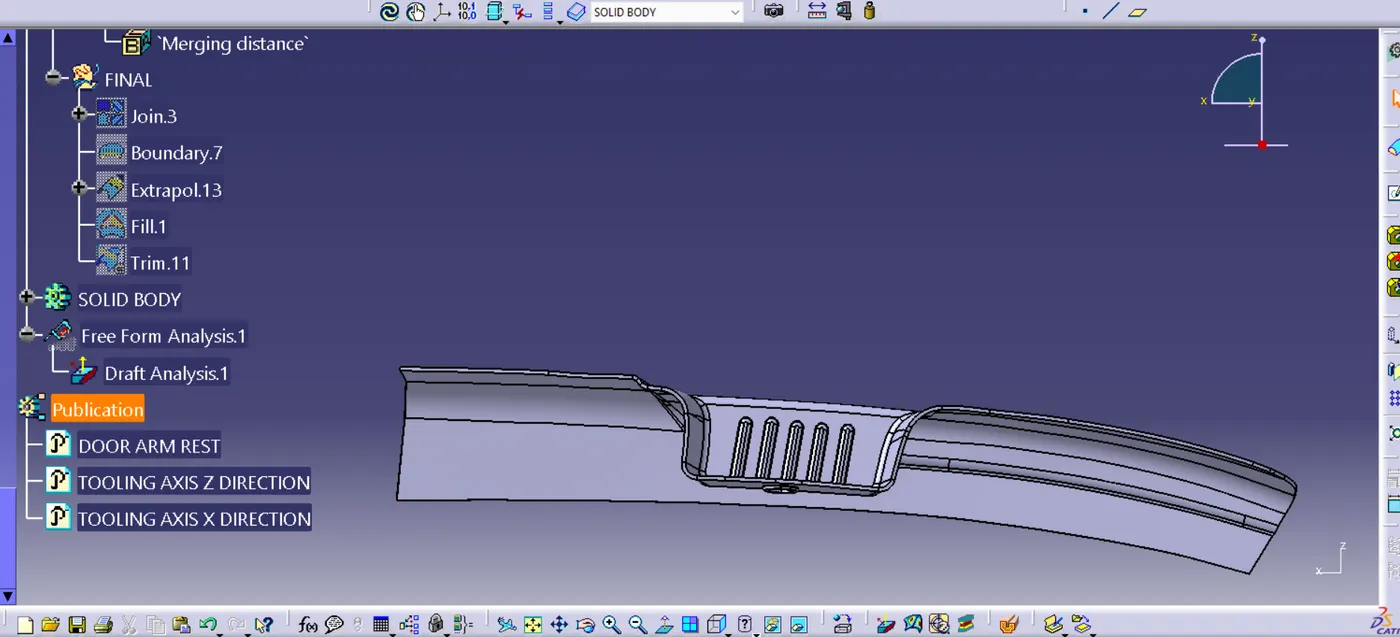
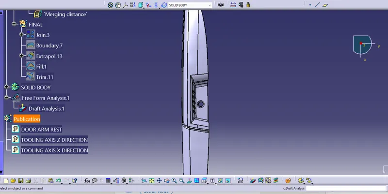
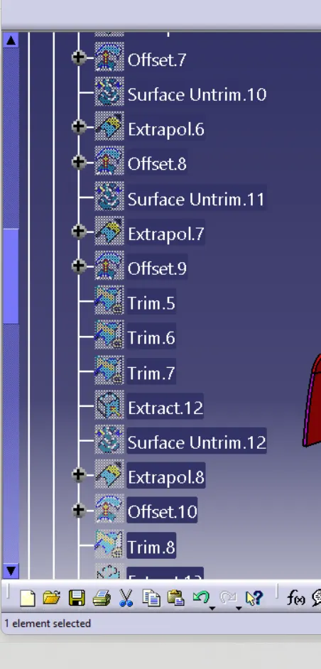
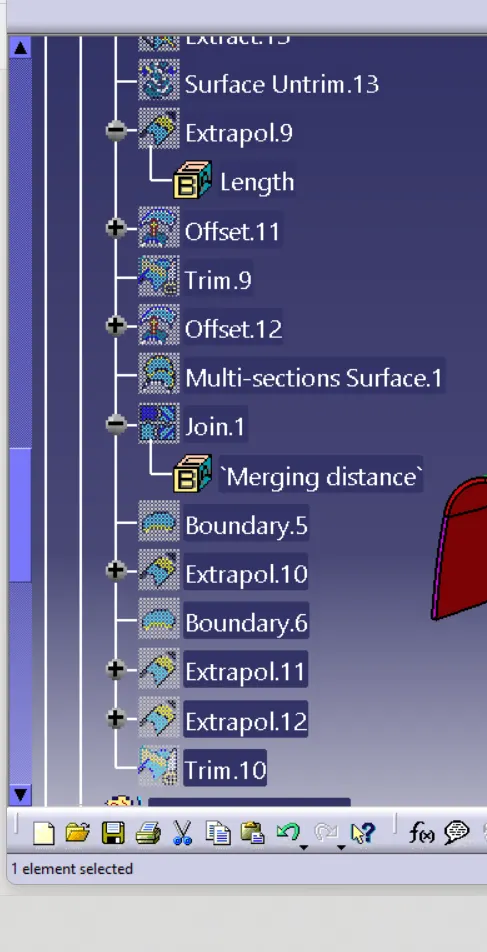
FEATURES TREE