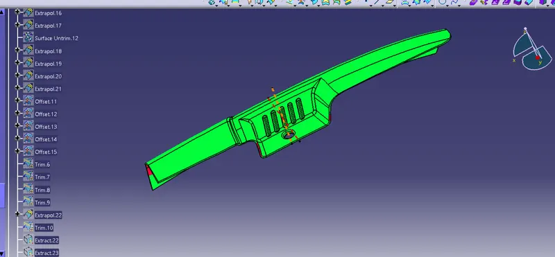
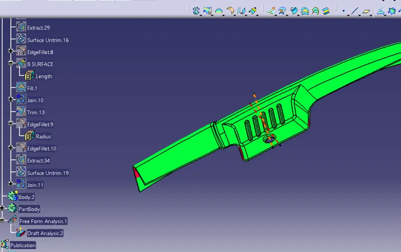
Door Arm Rest Week 8 Challenge
AIM-Creation of Door Arm rest and add thickness to it
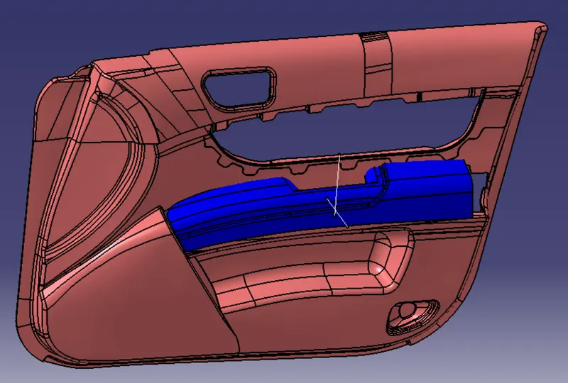
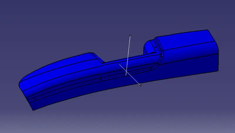
CHECK THE BOUNDARY OF DOOR ARM REST
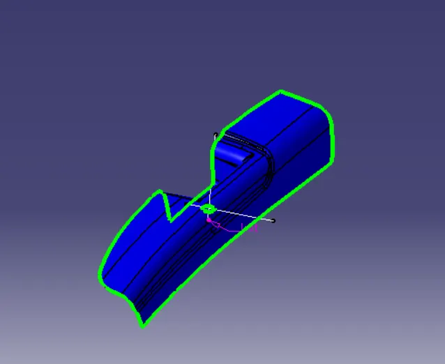
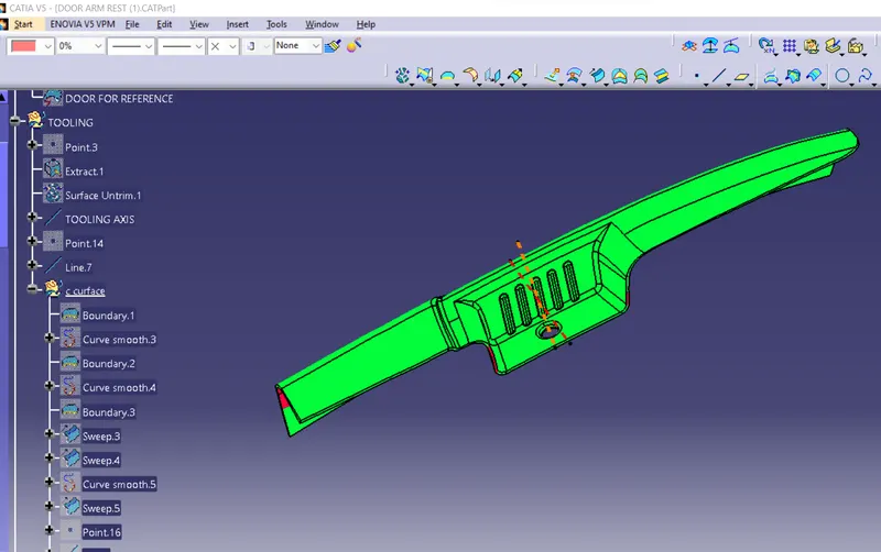
TOOLING AXIS CREATION
create a line center of hole with two point
create a axison z- axis generate a tooling axis
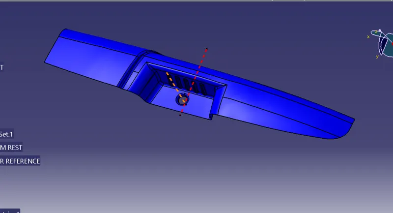
Compass Method:
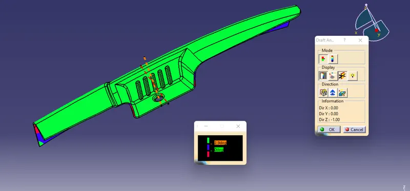
Checking draft analysis with dummy tooling axis and if tooling axis is not correct then adjusting compass to get the surfaces as green.
Then right click - lock current orientation - cancle draft analysis - select line - line direction - compass direction.
Then View - Reset compass
This line will be Main tooling axis.
'B' Surface Creation:
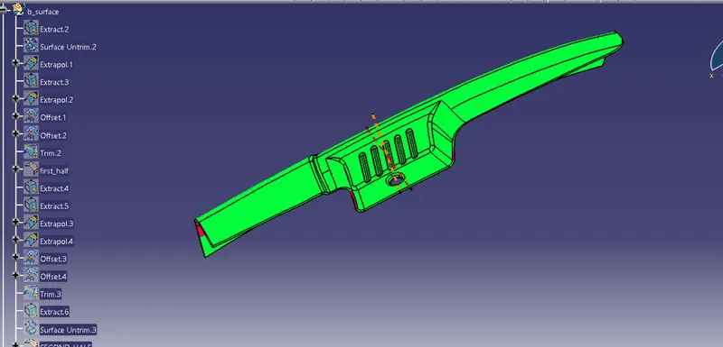
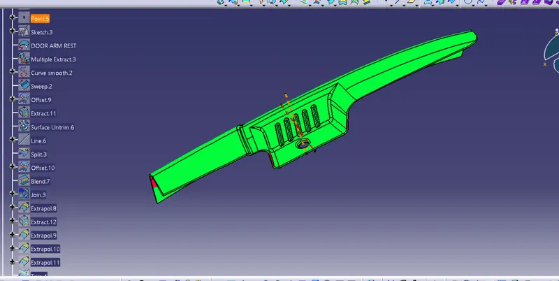
- Extract Class 'A' Surface.
- Untrim extracted surfaces.
- Extrapolate to some extend.
- Use trim and select proper surface.
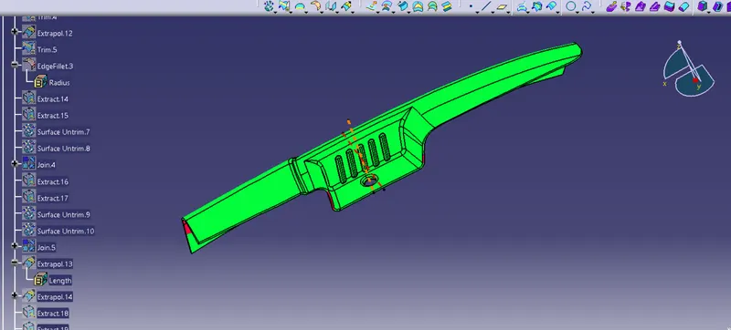
- . Offset inward at 2.5 mm
- Use edge fillet.
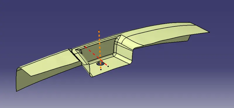
'C' Surface Creation:
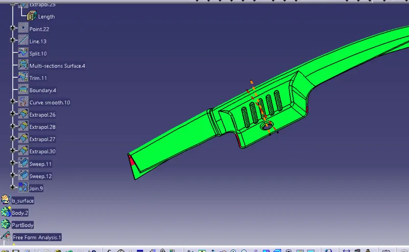
• Take outer boundary using Boundary command of class 'A' surface
• Use Smooth curve.
• Use sweep command to create surface using tooling axis and draft angle as 3 degree.
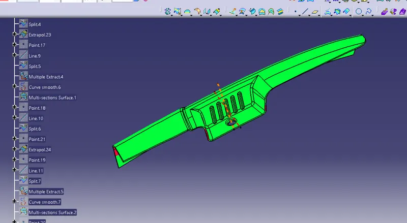
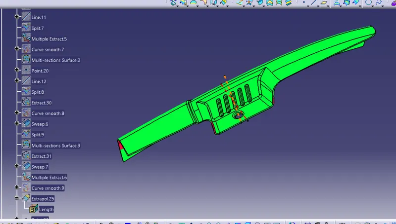
- Create points and line to split the surfaces as and where ever needed
• Join the split surfaces with multi section surface.
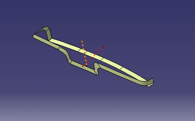
Final Body creation:
- Join class 'A' surface and 'C' surface.
- Trim resulting surface with 'B' surface.
- Join the surface.
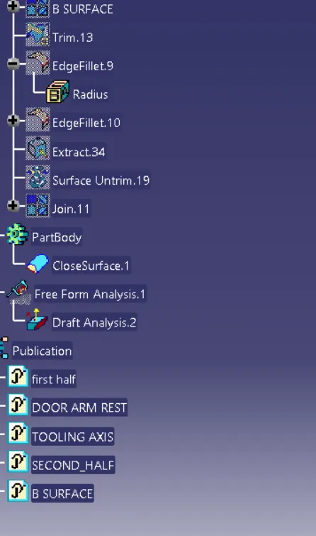
- Result is complete close surface.
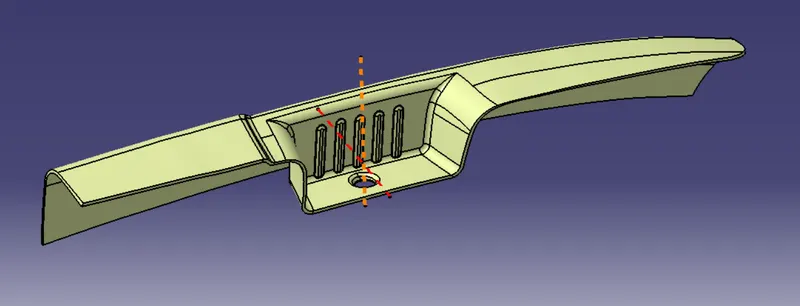
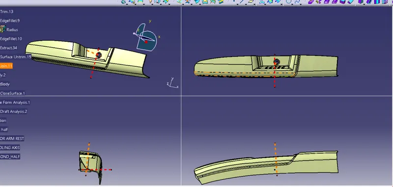
Solid Body:
- Change to Part workbench.
- Create Body.
- Surface Base Feature - Close surface - select last join.
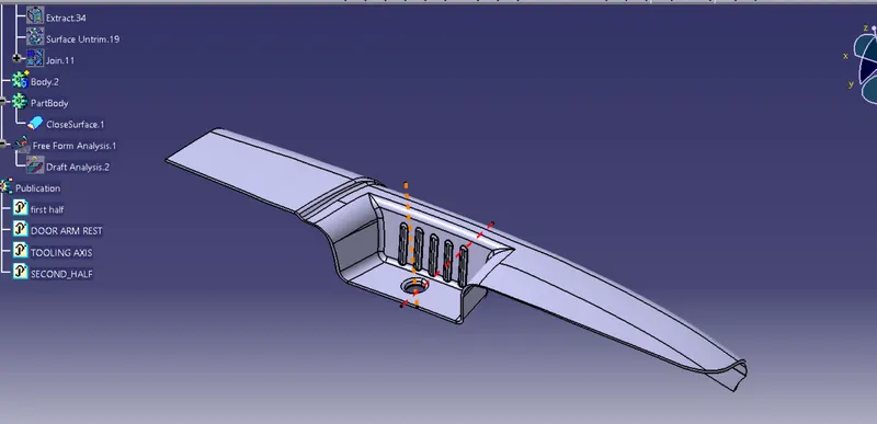
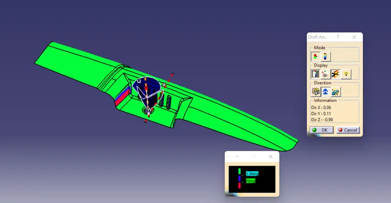
DRAFT ANALYSIS:
Open the Draft analysis by Insert > Analysis > Feature Draft Analysis..Select the Compass - Direction in Draft Analysis and align it to the
Tooling Axis and then lock it
After locking it a cross symbol will occur at the pointer,select the surface and the surface selected turns into green. In Draft Analysis 2 box,select the green column to change the draft and to 3 degrees.
The color should be green in colour.