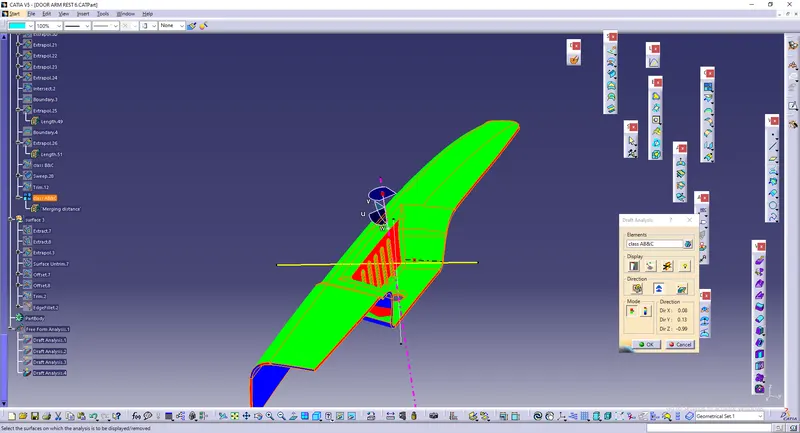
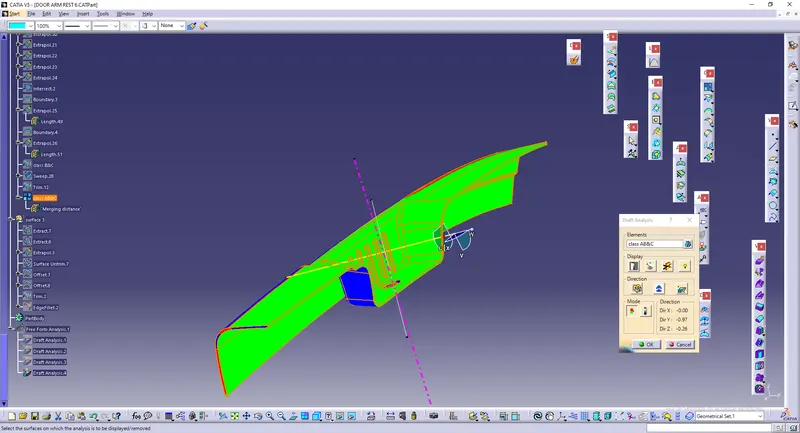
Door Arm Rest Week 8 Challenge
AIM : To create door arm rest and add thickness to it.
Commonly used commands or features.
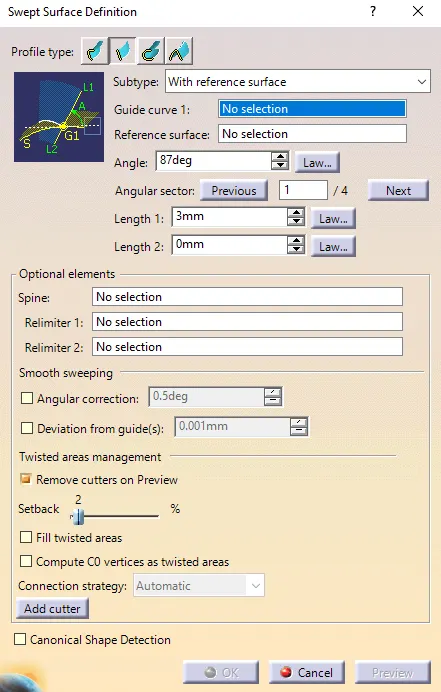
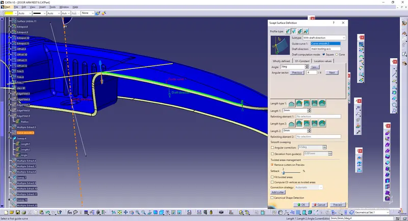
Sweep is used to generate surface along extracted boundaries. There are various methods of sweep.
Here we have used with reference surface. Where guide curve is selected as extracted boundary and reference surface is the one which is adjacent to the guide.
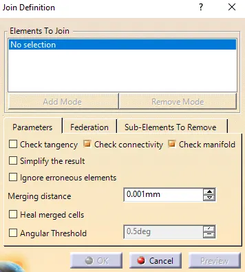
Join is used to attach surfaces or elements which are not together.
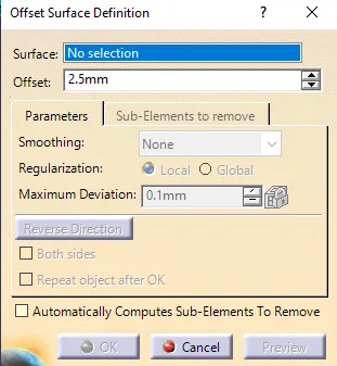
Offset is used to create a copy of a surface at a particular distance. The surface needs to be selected first and distance at which surface has to be offsetted has to be given
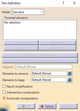
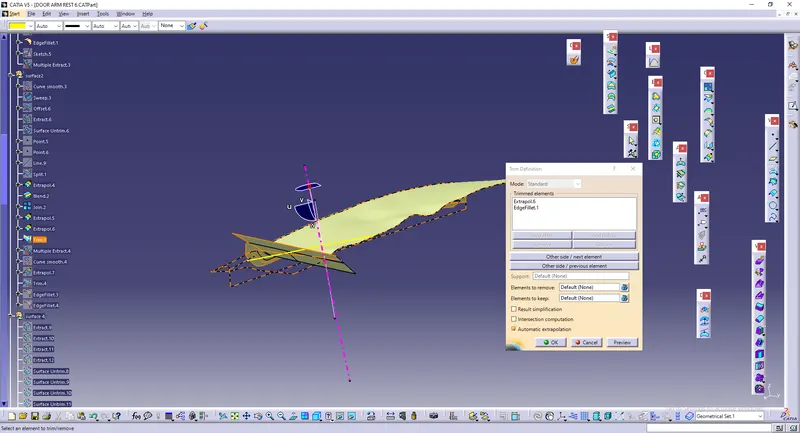
Trim is used to remove unwanted surfaces or elements. Make sure that the selected surface to intersect with each other
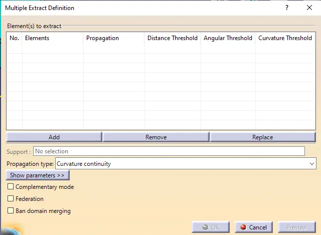
Multiple extraction is used to take out surfaces from parent and separate them. Edges can also be extracted and can be considered as boundaries.
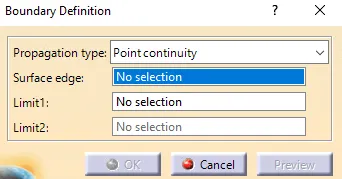
As the name insists, intersecting elements or edges are converted into a boundary.
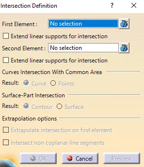
Intersection is used to create a boundary between intersecting surfaces or elements.
PROCESS :
Door arm rest was taken out and door panel was hidden first.
Class A surface is given.
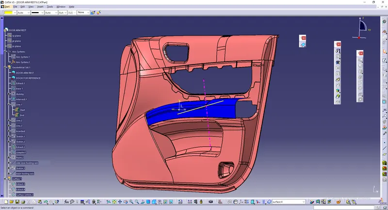
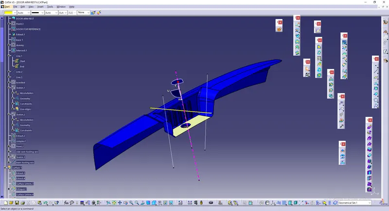
Tooling axis was created by creating a bisect between two lines. It was created by extracting bottom surface and using it as a reference.
Tooling axis refers to the direction at which mold or core and cavity opens.
Make sure that the axis be perpendiuclar to the surface.
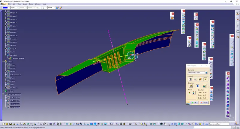
Draft analysis :
Draft analysis is done to ensure that the designed part can be easily removed or not. The maximum angle is set to be 3 and minimum 0.
The elements which lie between this range get cleared.
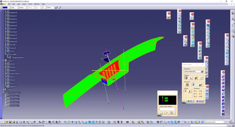
Side cores are used when a feature of an element cannot be directly made in a straight pull mold. In other words side core enable undercut geometry. Under cuts prevents ejection from mold.
In the below image, side core is given to clear undercut.
Class B
The flat surfaces in class A are extracted,untrimmed and extrapolated.
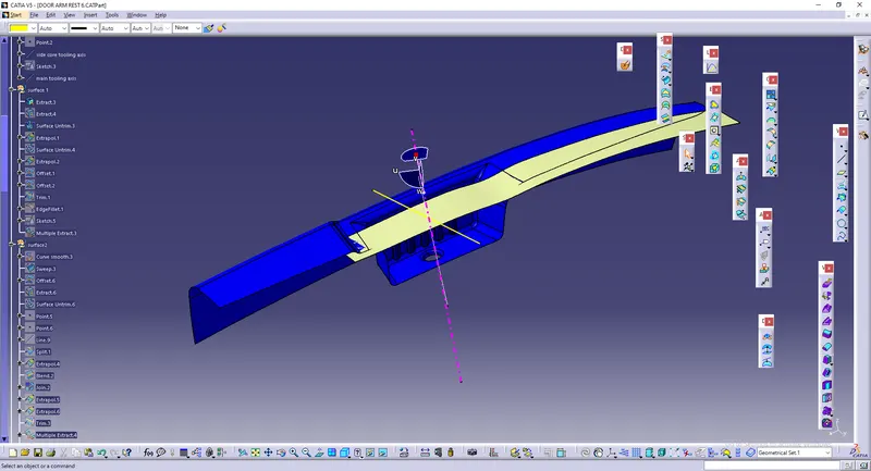
Offset of 2.5 mm is done after above operation.
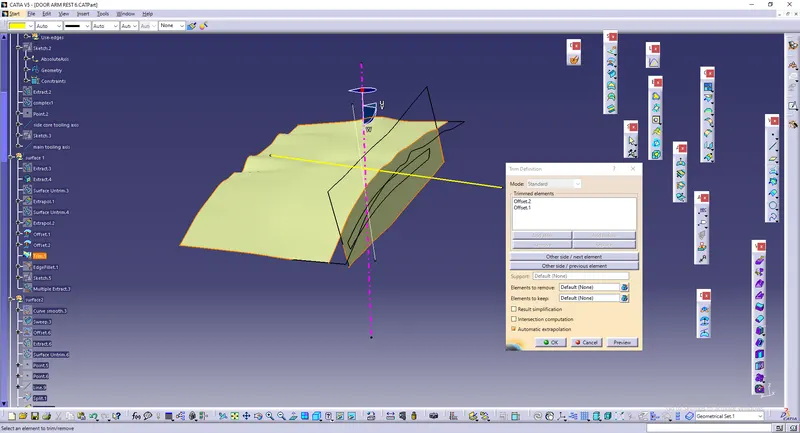
The intersecting surfaces are trimmed next to form a desired shape similar to Class A.
Complex feature are made next. Multiple extraction is used to take out edge. The created boundary is made into a smooth curve using curve smooth so that it wont be difficult while using sweep.
A small line is made which is used as tooling direction.
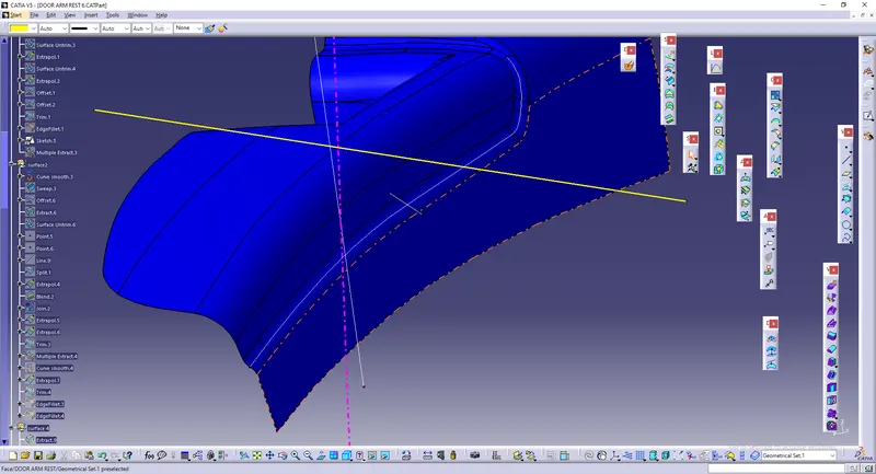
Sweep is then used to create surface given bvelow.
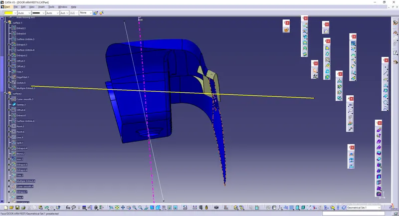
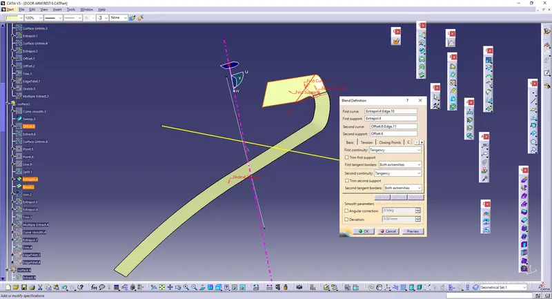
The adjacent surface is extracted and extrapolated. It is then joined together with the surface mentioned above using belnd.
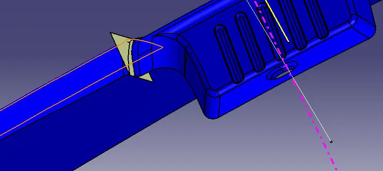
Blending.
Process is repeated fro other surface.
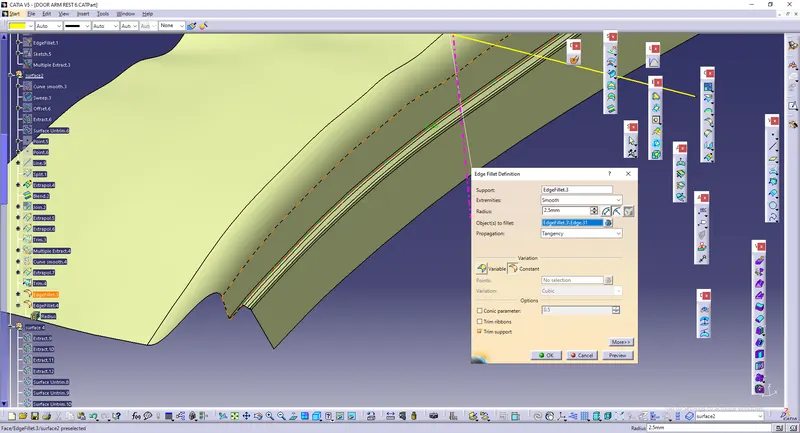
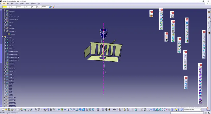
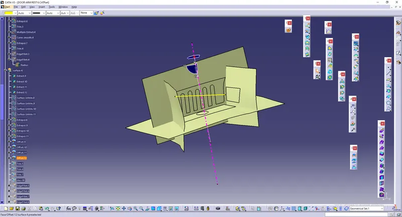
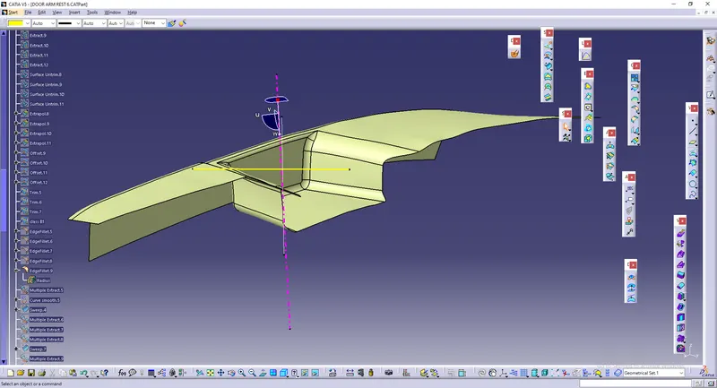
Class C surfaces are created by extracting edges from class A and creating a sweep using those edges as boundary (gudie curve) and tooling axis as draft direction.
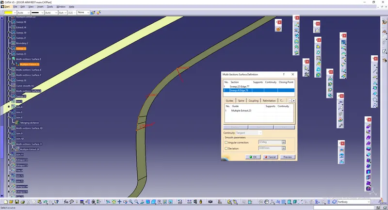
Multi section is used in fillet areas to reduce complexity.
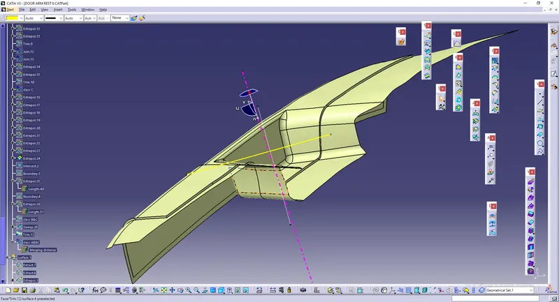
Join class ABC together.
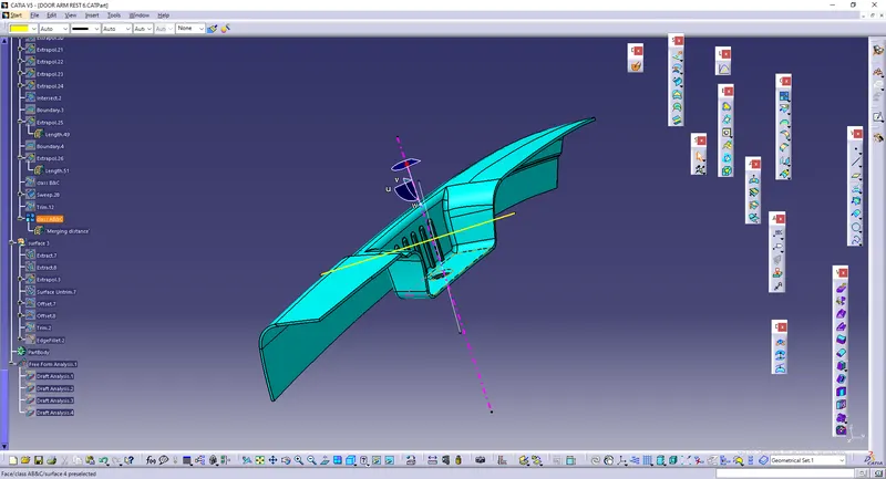
Drafting is done for class ABC all together.