Door Arm Rest Week 8 Challenge
AIM:-
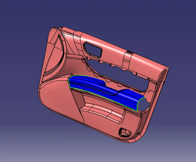
To create the part model of the surface class A provided by the creation of the B and C surfaces.
OBJECTIVE:-
The door armrest solid model with the design features involved and creation of the surface thickness necessary. Along with it considering the mold aspects and providing sufficient draft angle by the analysis tool to avail its feasibility.#
DOOR ARMREST:-
The door armrest provided in the cars is an interior part of it generally made up of thermoplastic polyurethane which is then injection molded and manufactured.
PART MODEL CREATION:-
- The part final model creation consists of three primary procedures.
- Class A surfacing initiates the product management, generally, they are created for the aesthetic feel and touch aspect in mind.
- Then the B surface is created where the engineering features are designed with the aspect and aiming to the product sustainability.
- Then the C surface conjoining the above two surfaces with a closed bounded which can then be further proceeded to the creation of the part model from the surface model.
DRAFT ANALYSIS:-
With the above said the features and aesthetic aspects now the mold feasibilities are an integral part of the design. The plastic product has a general positive draft angle of 3 degrees for the mold to be made without the defects.
The procedure is as follows:
- The center of gravity is analyzed by the inertia measuring tool.
- Then the tooling axis with the point along the axis perpendicular to the surface is created for draft analysis purposes.
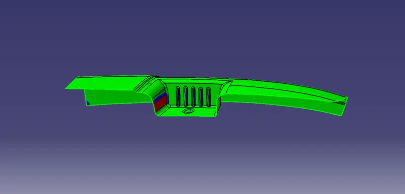
- Clearer from the picture the blue and red region depicts the draft angle provided along the tooling axis does not clear the surface due to the negative draft angle along those surfaces.
- This is termed as Undercut. They have to be cleared using a side core for which again axis definition has to be carried out.
SLIDER DIRECTION:-
- The side core for the negative draft along the stage right of the surface is cleared by creating an axis that is perpendicular i.e Y-axis here.
- Then the undercut in the walls is again cleared by another axis along the surface walls.
- Tilting the compass and adjusting would make the top surface clearer but since they are cleared in the main tooling axis hence such alignment would not be necessary.
CLASS B SURFACE:-
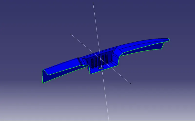
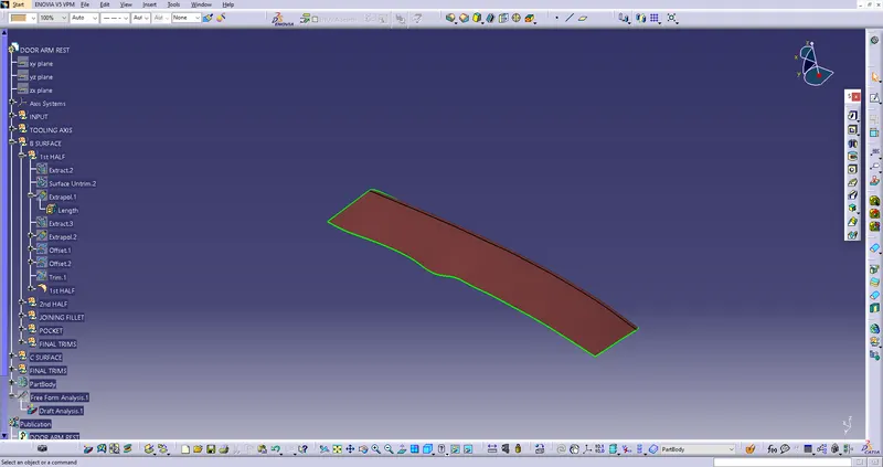
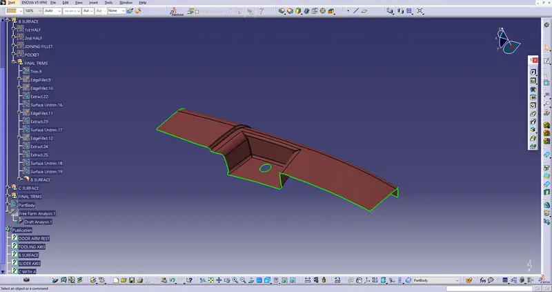
- The surface needed is extracted initially.
- Then they are untrimmed to clear out the features and get a plainer surface to work.
- Then the surface is given offset to 2.5 mm outside the Class A surface.
- Then the offset surface is extrapolated if needed to intersect during the trim operation.
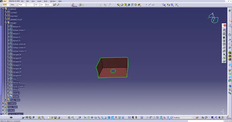
- The same procedure is carried out for the cavity base and walls. Then they are trimmed together.
- The same way the top surface of the part is extracted.
- Then they are trimmed, given offset to 2.5 mm and fillet is provided to their edge.
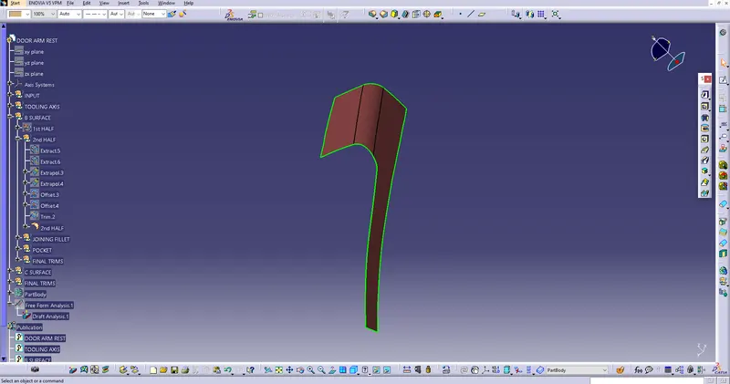
- The other side walls are extracted using the extract command.
- Surface after the extrapolation and trimming, offset and fillet to the edge.
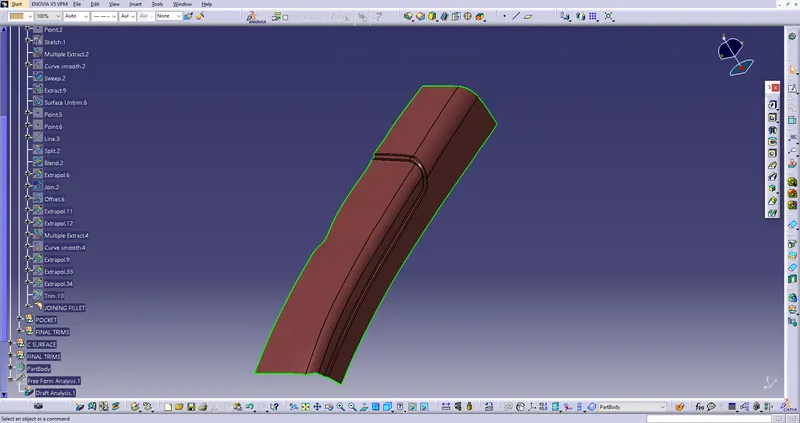
- Now the region in between these above surfaces has to be created.
- In order for this part, a sketch containing a line tangent to the surface is created, which is swept along.
- The corresponding rest profiles are extracted and then they are blended together followed by the join command.
- Then this is trimmed with the surface top on the part.
- Then with the other half of the created surface, these are being trimmed into.
- Which now is trimmed into the cavity surface created earlier and the fillets to the edge are given.
C SURFACE:-
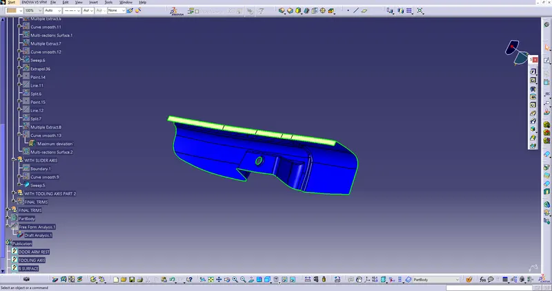
- Once the B surface is created, then the C surface is started.
- These surfaces are swept along the tooling direction for the common draft angle of 3 degrees.
- Then the frontal portion of the surfaces is extrapolated and created.
- Once the same way other surfaces are drafted and joined together, the C surface is conjoined with the A surface using the join command.
- Then the intersection curve is carried out to find the boundaries and non-connecting points. Then those are extrapolated to intersect the C surface.
- The end nodes are indicated by a black point which is not here denoting the surface intersection.
- Then they are trimmed together.
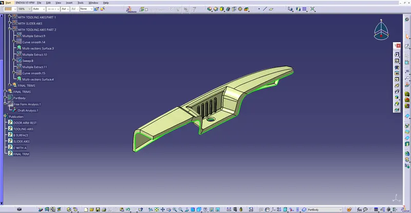
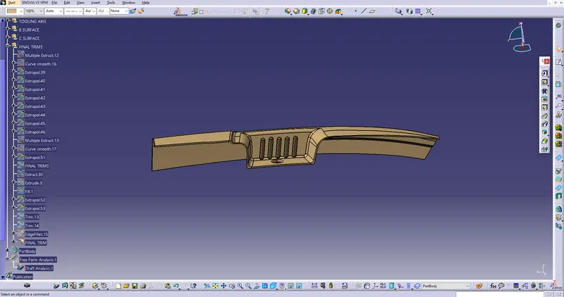
- The surface after the thickness being created with the draft.
- Then the closed body is carried out for the surface making it into a part component for further purpose.
CLOSED BODY:-
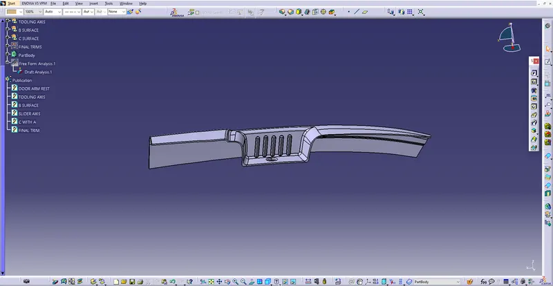
DRAFT ANALYSIS WITH RESPECT TO TOOLING AXIS:-
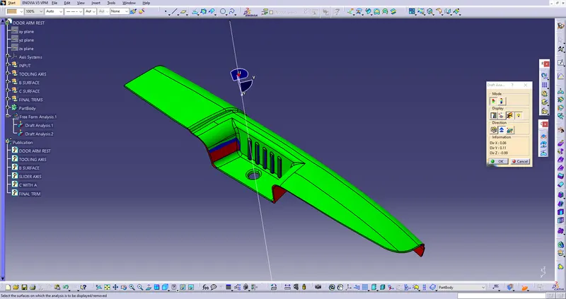
DRAFT ANALYSIS WITH RESPECT TO SLIDER AXIS:-
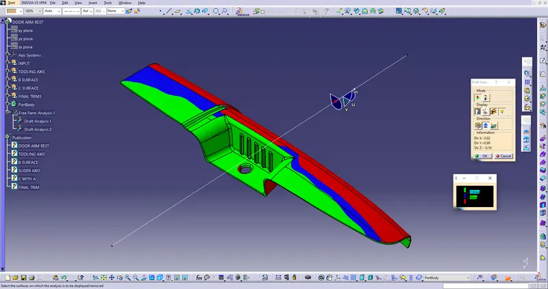
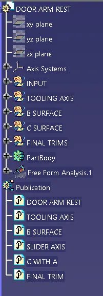
TREE STRUCTURE:-