Door Arm Rest Week 8 Challenge
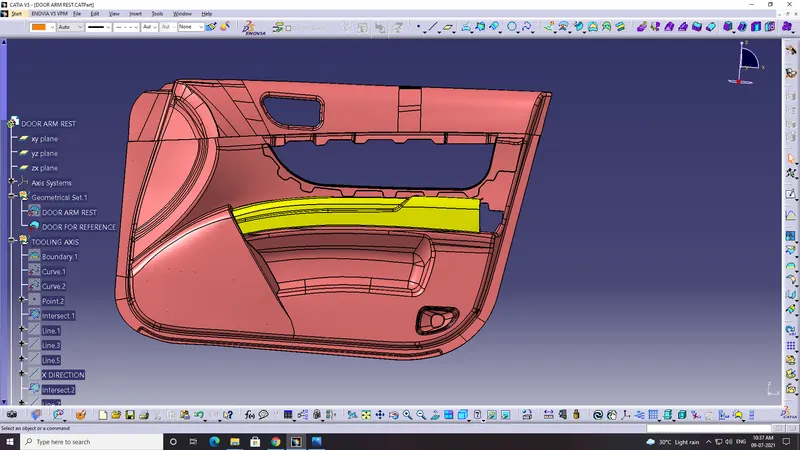
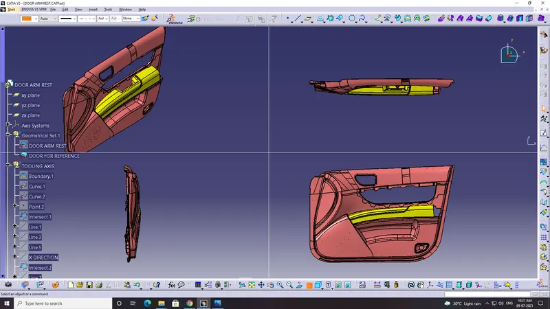
AIM : Creation of Door Arm rest and add thickness to it
Take the Thickness of the component to be 2.5 mm
DRAFT ANALYSIS :
- 1ST to check the connectivity of the class A surface.
- Ensure that there is no gap between the component, using join command .
- We can visually check it or by clicking boundary command.
- After that disassembled
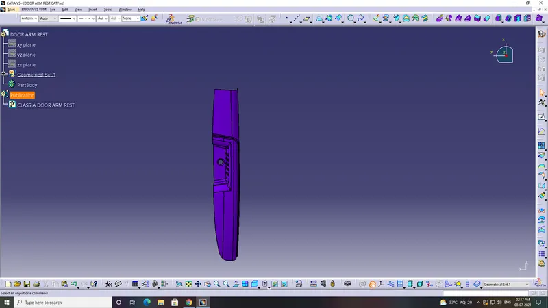
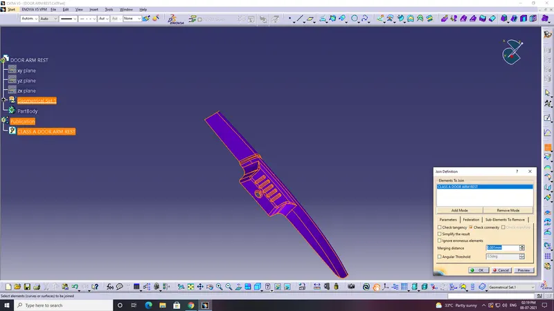
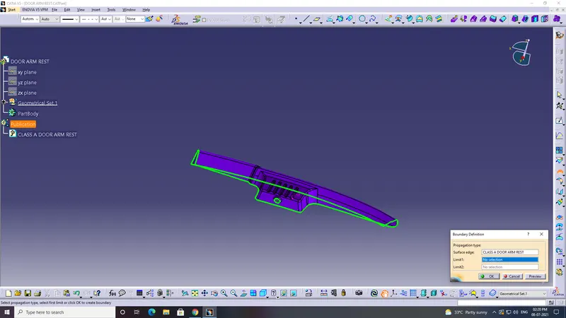
- It has 2 boundary. inner and outer.
so the 1st design check is completed.
step 2: Find the toling axis of the component.The tooling axis is nothing but the mould opens or cavity opens.
- Check visually which is the best possible tooling direction.
- check all the 3 axis.
- Along x and y is not possible.
- Z is the best possible tooling axis.
Create a tooling axis along x and y.
ntersect the zx plane with the fan component. As the result get 2 line of zx plane.
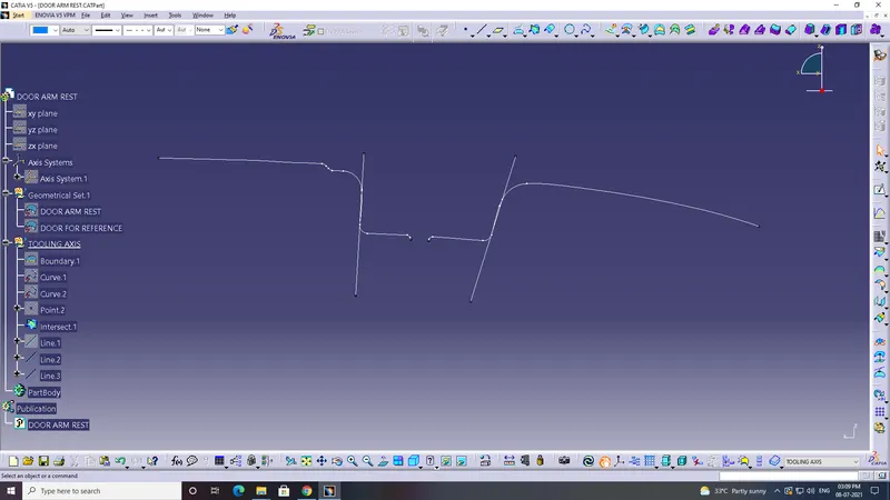
Draw a line along z direction to help visulation to create a dummy tooling line axis.
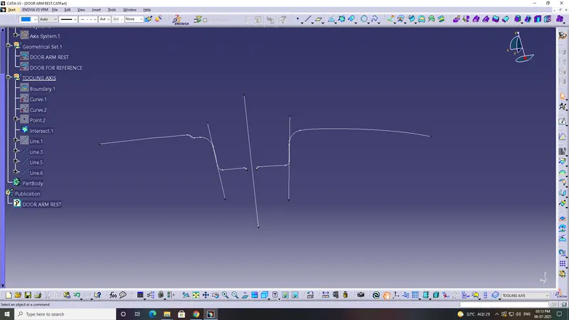
Ater that created the tooling clearing X direction.
Next need to create along z direction for the tooling clearing Y direction.
same procedure for the other side
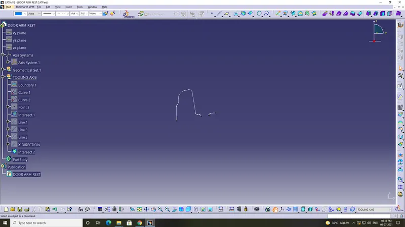
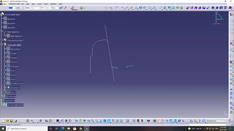
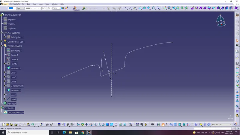
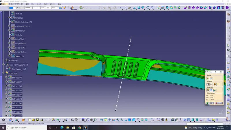
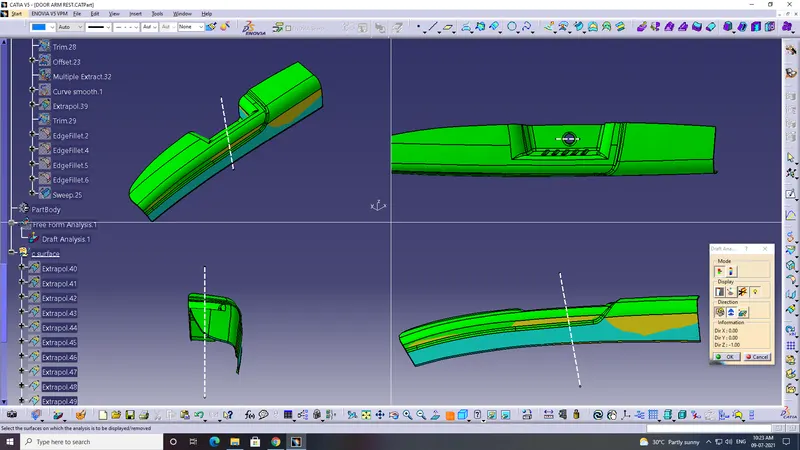
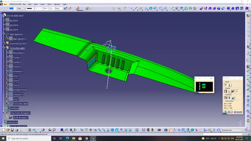
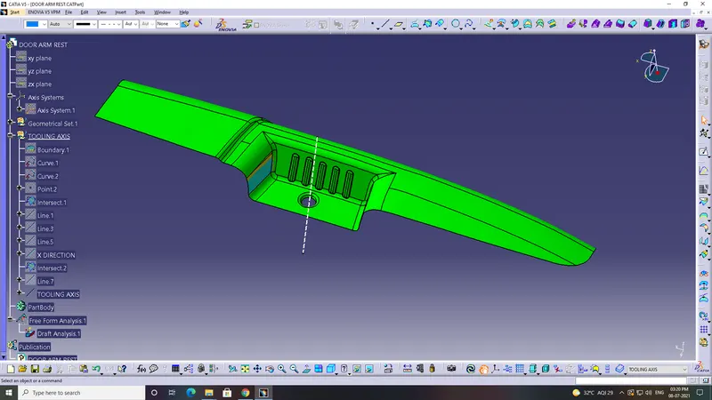
now this is the draft analyst tool.
And next place the axis and lock it.
It displayed in green color.
more than 3 is green.z is red and negative is blue.
minimum draft value is 3.
Now measure individually
SLIDING TOOLING DIRECTION:
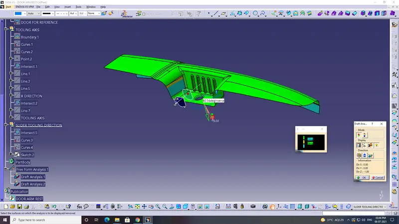
cutout is not clear in the main tooling direction.and now to make a new tooling direction by cutout.
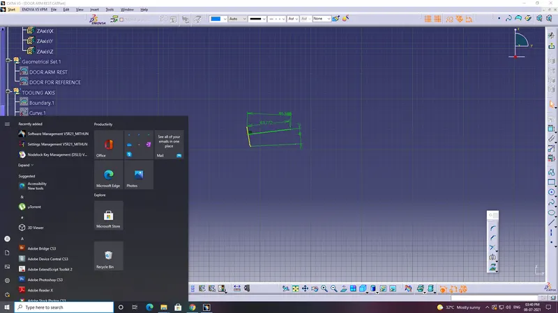
and we can make a intersect between them.make a sketch on z y plane and create a intersection them and give upto 4 deg.
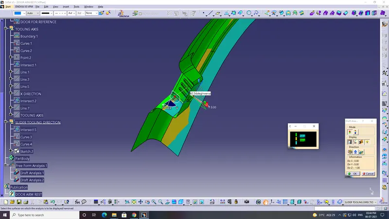
Give boundary and disassambled and give domian 2 only
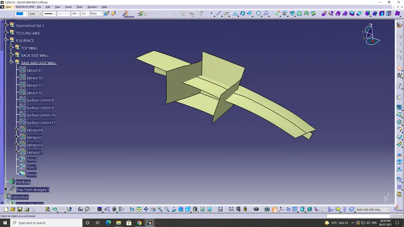
Create a geometric set and name as B SURFACE ------ SIDE WALL SURFACE.
Extract the ALL four side surface without the fillets and give no propagation.
untrim the surface.
Extrapolate 20 mm with point continuity.
trim it.
Hide the extract.
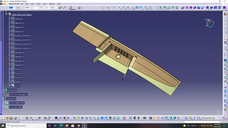
and give the offset value of 2.5mm.
fter that create apropretae for all side wall and tha base
Extract the all side walls and give no propagation.
untrim the surface.
Hide the extract.
and give the offset value of 2.5mm.
Extract the base and give no propagation.
untrim the surface.
Hide the extract.
and give the offset value of 2.5mm.
as same as above and trim it.
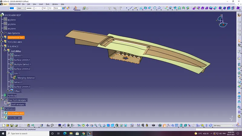
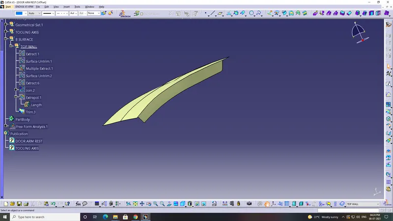
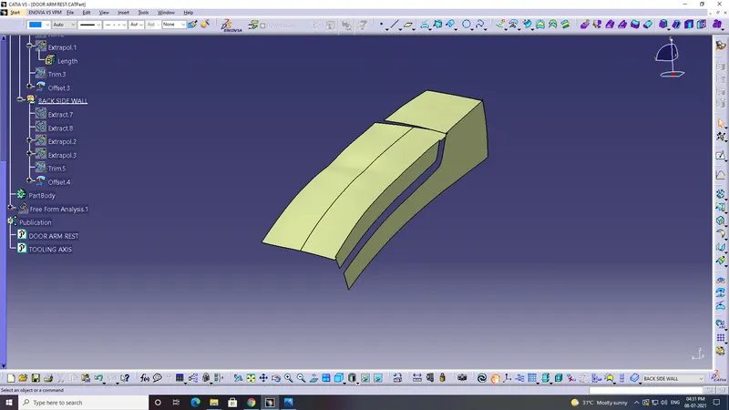
Give the offset to the trim.2 about 2.5.
Because the thickness of the component is 2.5. so that's why the offset value is 2.5.
And next create the 2nd geometric in the B surface ------ rib2 .
what ever did in the rib 1 same as gonna do in the rib 2.
Extract the side of the rib.
Give untrim one by one side rib.
After the untrim one by one side rib. Go to the tree hide the extracts.
Extrapol them in 10 mm.
Always ensure that in Continuity : curvature. Propagation mode : Point continuity.
Trim the surface and extrapol using trim command.
Give the offset to the trim.2 about 2.5.
Because the thickness of the component is 2.5. so that's why the offset value is 2.5.
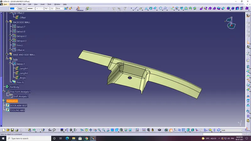
AND now create c surface.
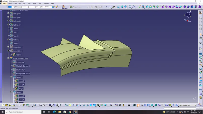
Give the class B intersection along yz plane.
sweeep methode 2.
boundary
and give multiple extract.
and give sept.
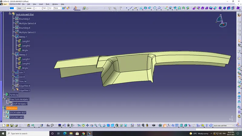
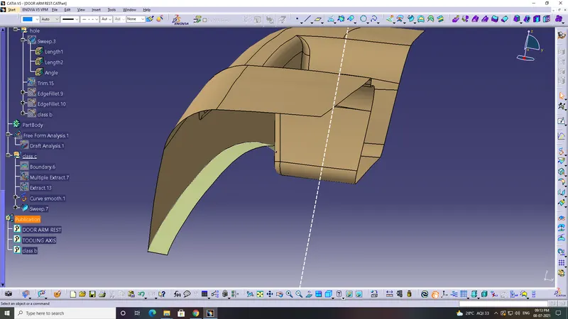
give sweep command. ensure that in profile type in 2nd one.
subtype ---- with reference surface
G.C ------ boundray.
reference : multple extract
angle : 90
length : 5mm
since the thickness is 2.5 mm so give the extra 1 or 2mm.
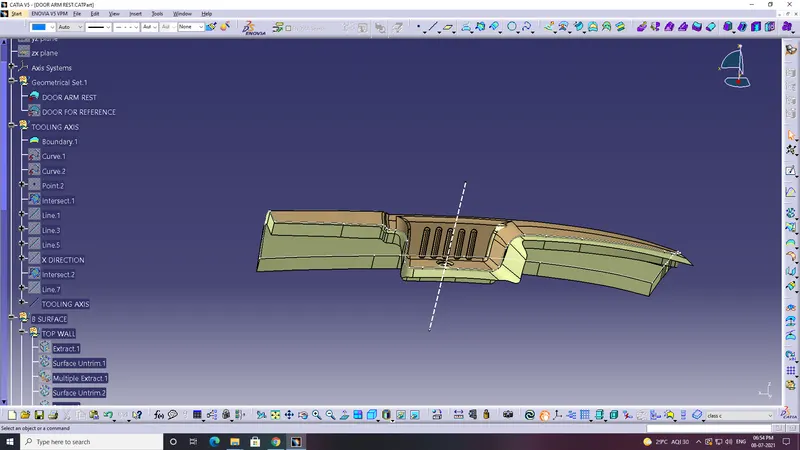
and publish the
- CLASS A SURFACE.
- TOOLING AXIS.
- CLASS B SURFACE.
- CLASS C SURFACE.
- CLOSED SURFACE.
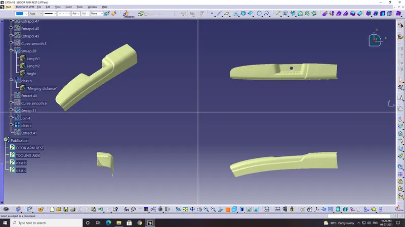
FINAL COMPONENT DRFAT ANALYSIS
now this is the draft analyst tool.
And next place the axis and lock it.
It displayed in green color.