Development of lower door trim from class A surface
OBJECTIVE:
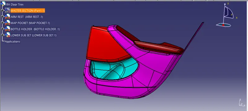
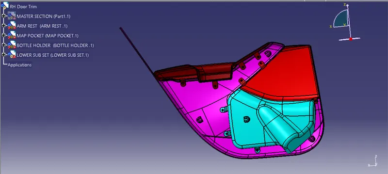
To make a solid body of a side door trim of a vehicle from the given class As of 4 parts. Also, B side features like doghouse, heat stake and locator should be added, all obeying the design rules and guidelines.
THEORY
Role of plastics in the Automotive industry
Plastics have played an important role in the automotive industry for several decades. They are used in a wide variety of applications, from exterior body parts to interior components and electrical systems. Here are some of the key ways in which plastics are used in the automotive industry:
-
Lightweighting: Plastics are lightweight and can help reduce the weight of a vehicle, which can improve fuel efficiency and reduce emissions.
-
Design flexibility: Plastics can be molded into complex shapes, which allows automotive designers to create unique and aerodynamic designs that are difficult to achieve with other materials.
-
Durability: Plastics are durable and can withstand exposure to heat, cold, and chemicals, making them ideal for use in harsh automotive environments.
-
Cost-effectiveness: Plastics are often less expensive than other materials, which can help reduce the overall cost of producing a vehicle.
-
Noise reduction: Plastics can help reduce noise and vibration in a vehicle, improving overall comfort for passengers.
-
Safety: Plastics can be engineered to absorb impact and provide crash protection, which is crucial for vehicle safety.
Some specific applications of plastics in the automotive industry include:
- Exterior body parts such as bumpers, grilles, and body panels
- Interior components such as dashboards, door panels, and seat backs
- Electrical components such as wiring harnesses and connectors
- Engine components such as intake manifolds and valve covers
Overall, plastics have become a vital material in the automotive industry due to their versatility, durability, and cost-effectiveness. As the industry continues to focus on reducing weight and improving fuel efficiency, it is likely that the use of plastics in automotive applications will continue to grow.
Here are four reasons why plastic is used in car manufacturing:
- Plastics reduce the weight of cars
- Plastics and polymers contribute to the safety of cars
- Plastics help to lower car manufacturing costs
- Polymers advance the design of vehicles
MANUFACTURING PROCESS:
INJECTION MOULDING:
Injection molding is a manufacturing process used to produce plastic parts by injecting molten plastic material into a mold. The process is commonly used for mass production of plastic parts that have a consistent shape and size. The steps involved in injection molding are:
Designing the part: The first step in the injection molding process is to design the part that is to be manufactured using computer-aided design (CAD) software.
Creating the mold: A mold is then created based on the design of the part. The mold is typically made of metal and consists of two halves, a stationary half and a movable half, which can be opened and closed by a hydraulic or mechanical system.
Preparing the material: The plastic material used for injection molding is typically in the form of small pellets or granules. These are loaded into a hopper, which feeds the material into the injection molding machine.
Melting the material: The plastic material is melted in the injection molding machine using a heating element or a screw that melts the material and pushes it into the mold.
Injecting the material: Once the plastic material is melted, it is injected into the mold under high pressure. The mold is held closed by the machine's clamping unit to prevent the plastic from leaking out.
Cooling the part: After the plastic has been injected into the mold, it is allowed to cool and solidify. The cooling time depends on the thickness of the part and the specific plastic being used.
Ejecting the part: Once the part has cooled and solidified, the mold is opened and the part is ejected from the mold using ejection pins or a robotic arm.
Repeat: The process is then repeated to produce additional parts.
Injection molding is a versatile and efficient process that can produce parts with a high level of accuracy and consistency. The process is widely used in industries such as automotive, medical, consumer goods, and packaging.
TOOLING DIRECTION FOR PLASTIC PART:
Tooling direction is main consideration for plastic part and mold parts because it defines movement of mold part and possibility of plastic part to come-out from mold part (Core and Cavity).
- In Molding machine arrangement is given to open the mold along a direction which is known as Tooling Direction.
- In other words. The mold is built from two separate halves (Core and Cavity) and tooling direction basically define the direction of mold pulls apart.
- Tooling direction is known as primary direction.
- Core is the male part of the mould which holds the inner design of the component and the cavity is the female part which holds the outer shape of the component.
Tooling direction, also known as mold flow direction, refers to the direction in which the molten plastic material flows into a mold during the injection molding process. The direction of the flow can have an impact on the properties and appearance of the finished product, as well as the ease and efficiency of the molding process.
When designing a mold for injection molding, the tooling direction is an important consideration. The tooling direction can affect the strength, appearance, and function of the finished part. The tooling direction also impacts the flow of plastic material in the mold, which can affect the filling and packing of the part.
There are generally two types of tooling direction: a longitudinal tooling direction and a transverse tooling direction. A longitudinal tooling direction is parallel to the longest dimension of the part, while a transverse tooling direction is perpendicular to the longest dimension of the part. The choice of tooling direction depends on the specific requirements of the part being molded and the desired properties of the finished product.
The tooling direction can also affect the cost and complexity of the mold. A mold with a transverse tooling direction may require more complex and costly tooling, as the plastic material needs to flow through thinner sections of the mold. In contrast, a mold with a longitudinal tooling direction may require less complex tooling and can be more cost-effective.
In summary, tooling direction is an important consideration in the injection molding process, as it can impact the properties, appearance, and efficiency of the molding process. The choice of tooling direction depends on the specific requirements of the part being molded, the desired properties of the finished product, and the cost and complexity of the mold.
THE FOLOWING PROCEDURE FOLLOWED BY THE PLASTIC DESIGNS :
1.SURFACE CLASSES:
all plastic parts are made by number of surfaces.while proper understanding while designing the plastic parts.
all surfaces are classified into three groups there are
1) A-surface
2) B- surafce
3) C-surface
1.1 A- CLASS SURFACE :
how it look/visible the product in our view tells us the class -A.
Following points are related to A-Surfaces :-
- To design the outer visible surface of part
- Design in this way to maintain aesthetic look of parts .
- A- surface may have texture
- A - suraface gave curvature continuity
- A-surface don't have any ribs,bosses ,snap or gussets.
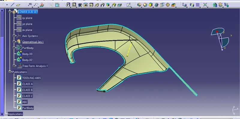
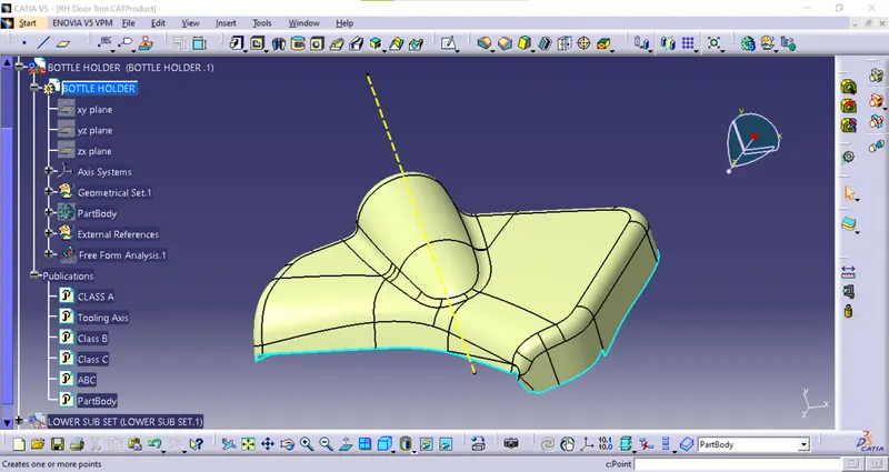
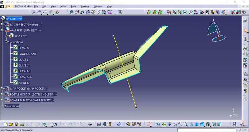
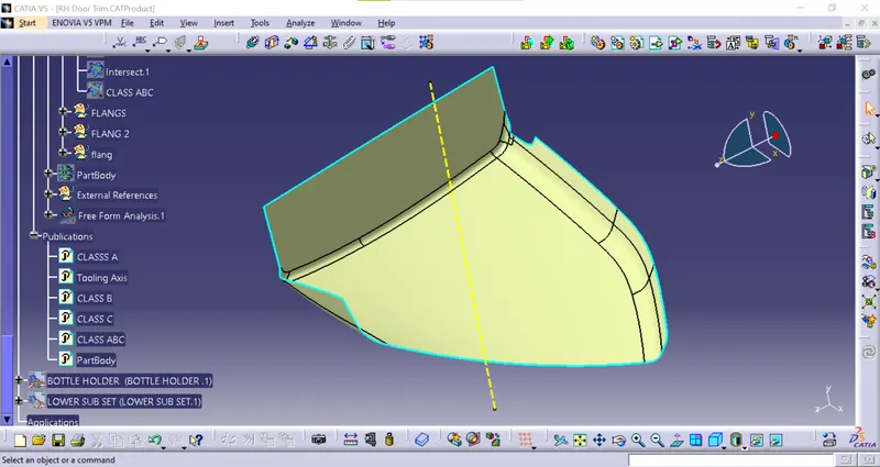
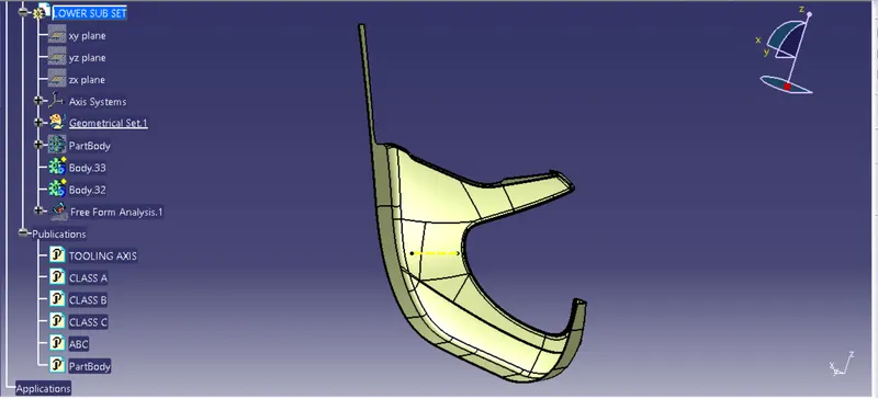
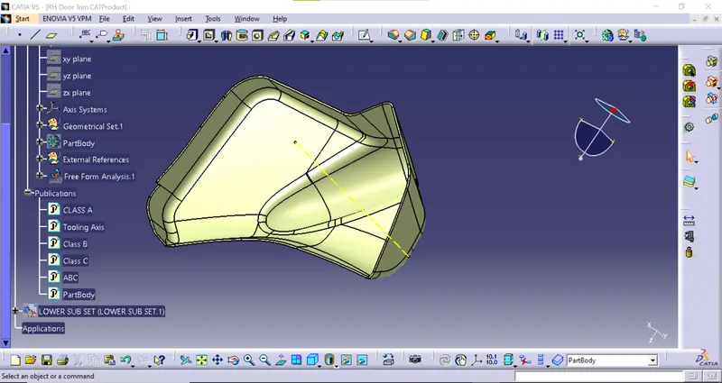
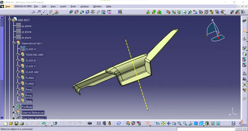
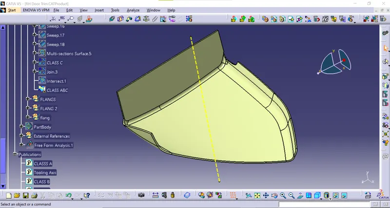
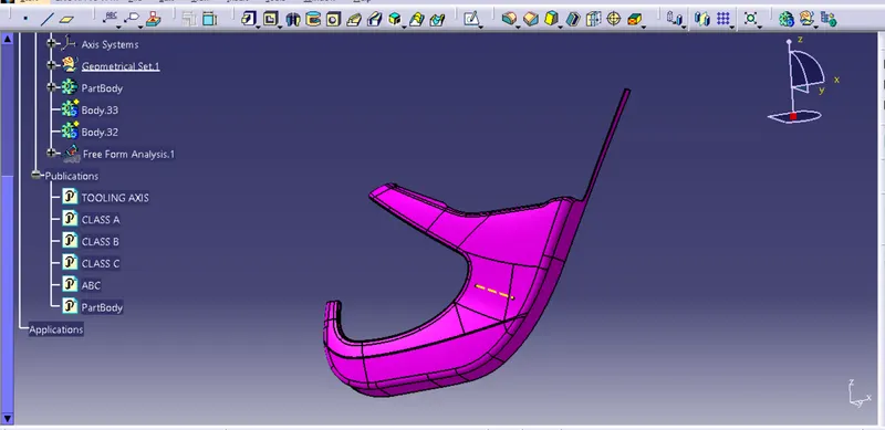
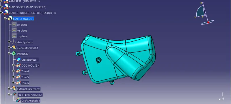
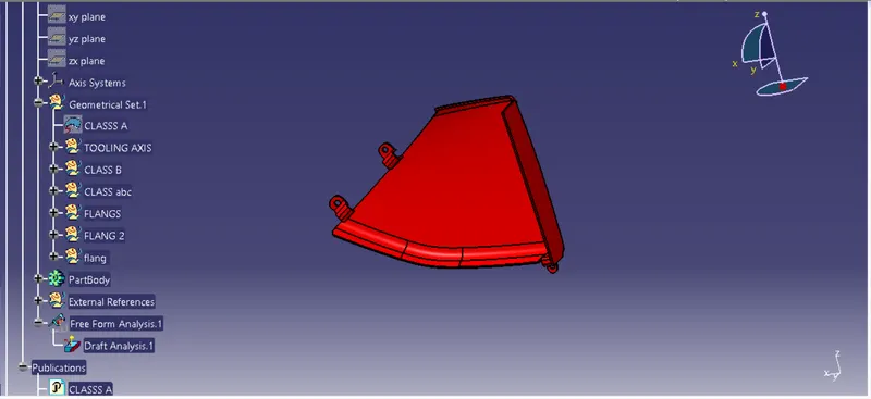
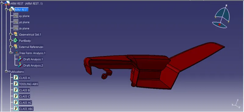
The first step to follow in this project is to extract the CLASS-A surface (individually for each component) of the Door Trim Panel and divide these surfaces into different Geometrical sets as follows.
1.Door Arm rest
2.Lower Substrate
3.Upper Substrate or Map Pocket
4.Bottle handle
TOOLING AXIS CREATION:
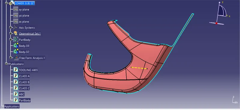
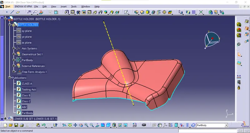
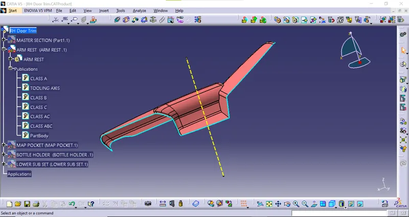
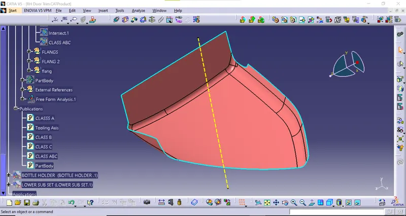
Tooling axis plays important role in plastic product manufacturing and designing, this axis decides the direction in which mould is going to work while production of the component
To create a tooling axis in CATIA V5, you can follow these steps:
- Open the part file in which you want to create the tooling axis.
- Switch to the "Wireframe and Surface Design" workbench by clicking on the corresponding icon in the toolbar.
- Click on the "Axis" icon in the "Wireframe" toolbar.
- Select the edge or curve that you want to use as the axis for your tool.
- Click on the "Offset" icon in the "Wireframe" toolbar.
- Specify the distance from the selected axis to create the offset.
- Click on the "Axis System" icon in the "Wireframe" toolbar.
- Select the axis that you created in step 4.
- Specify the orientation of the new axis system by selecting two points on the surface of the part.
- Click "OK" to create the new tooling axis.
1.Lower Subset
2.Bottle Holder
3.Arm Rest
4.Map Pocket
DRAFT ANALYSIS:
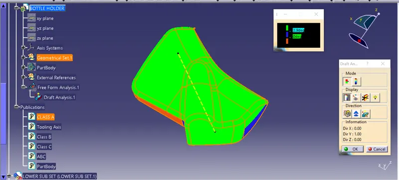
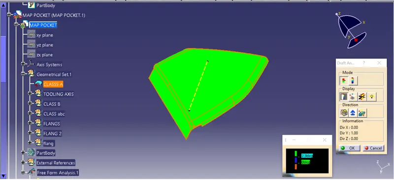
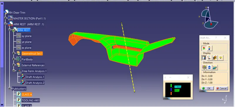
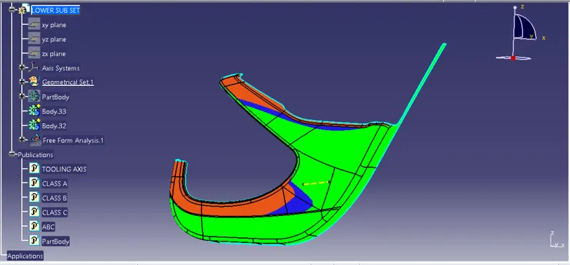
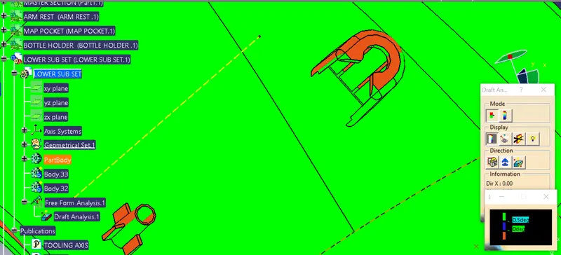
- Final plastic parts are the nominal draft angle is 3 degrees but even 7degree is allowed for the subassemblies like ribs and slots.
- Insert< Analysis< Feature draft analysis
- First the compass is moved to the part which used to define the tooling axis new current draft direction then lock the draft direction using the lock icon.
- The color of the chart indicates the draft if the color is indicated that means the part passes and used for further operation.
- By using the analysis under the running point icon, we can check draft angle at the various surface of the component.
- If the surface satisfied the draft angle, then it shows the green color if not appears in red color.
Example
CLASS B SURFACE :-
B- surface is invisible to viewer
FOLLOWING POINT RELATED TO B -SURFACE :-
1.To design the inner invisible surface of part
2.design in the way to maintain volume of inner hollow portion
3.B-surface have tangent continuity
4.B-surface don't have texture
5.B-surfaces need to be created according to A- surfaces
Class B surfaces are a type of surface in CAD (Computer-Aided Design) modeling that are used to define the internal structure of a product, often for components that are not visible from the outside or that do not have complex curves or shapes.
Unlike Class A and Class C surfaces, Class B surfaces do not need to have a high level of aesthetic quality or accuracy. Instead, they are used to define the internal geometry of a product, such as the structural supports, mounting points, and other features that are necessary for the product to function properly.
Class B surfaces are typically created using simpler surface creation tools and techniques, such as extruding and revolving curves, as well as using standard geometric shapes such as cylinders, spheres, and cubes. These surfaces may also be created by offsetting or extending other surfaces, such as Class A or Class C surfaces.
CLASS C SURFACE :-
C -Class surfaces are created to class A & B
FOLLOWING POINT RELATED TO C - SURFACE :
- C- class surface are created to close A ,B & C
- C - Surfaces don't have texture
- C -surface don't need any type of tangent continuity
- it is using engineering patches or using reference of environmental parts
A Class C surface is a type of surface in CAD (Computer-Aided Design) modeling that is commonly used in the automotive industry to define the shape of car bodies, particularly for exterior body panels. Class C surfaces are also known as "Aesthetic Surfaces" because they are used to define the visible, curved surfaces of a car body.
Class C surfaces are defined by curves and continuous surfaces that are smooth and aesthetically pleasing to the eye. They are often created using spline or NURBS (Non-Uniform Rational B-Splines) curves, which are commonly used in 3D modeling and computer graphics. Class C surfaces are also characterized by their high quality and accuracy, as they must match the precise specifications of the car body design.
Class C surfaces are often used in conjunction with Class A surfaces, which are used to define the more complex and detailed features of the car body, such as the headlights, grille, and other smaller details. Together, Class A and Class C surfaces create the final, detailed surface geometry of the car body.
Overall, Class C surfaces are an essential part of the automotive design process and play a critical role in creating the final, aesthetically pleasing exterior of the car.
example
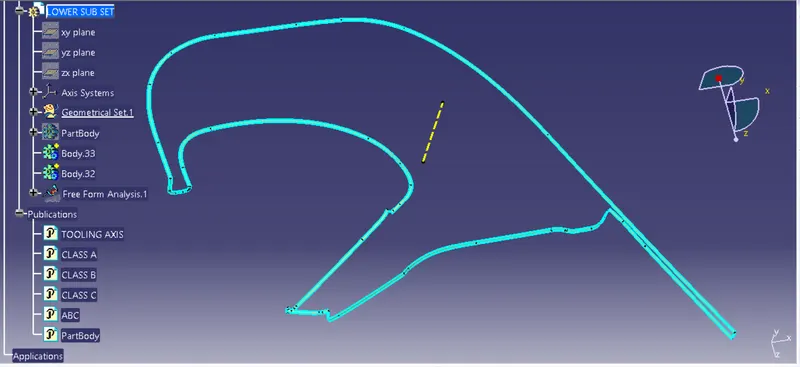
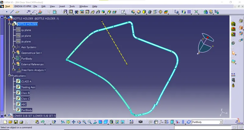
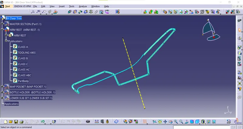
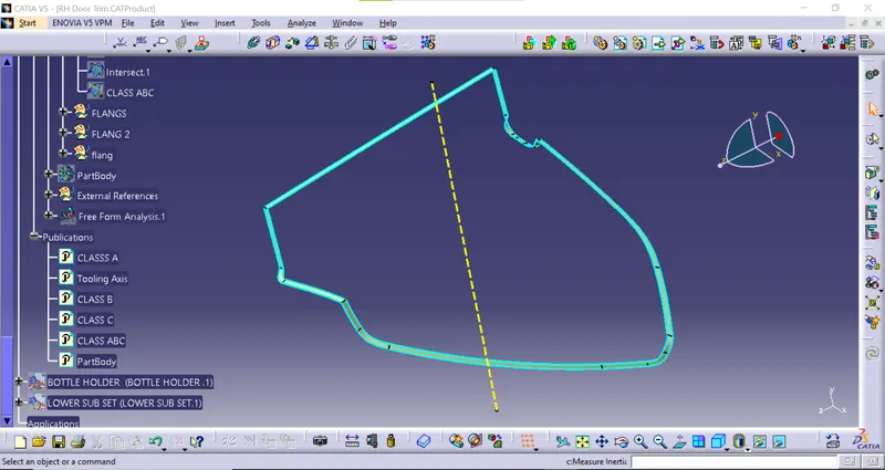
ABC Example
B-Side Featers And Flanges
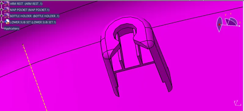
DOG HOUSE :
Dog house is an engineering feature used in plastic trim design. Dog houses are used as supporting feature. Sometimes other engineering features like snaps; locators etc. are mouted on them to increase their strength.
To draw a dog house in CATIA V5, you can follow these steps:
Open CATIA V5 and create a new part.
Click on the Sketcher icon in the toolbar to enter the sketching mode.
Use the Line command to draw a rectangle as the base of the dog house. Specify the dimensions of the rectangle as required.
Use the Offset command to draw a smaller rectangle inside the first rectangle, representing the wall thickness of the dog house. Specify the offset distance as required.
Use the Line command to draw a triangle on top of the smaller rectangle, representing the roof of the dog house.
Use the Trim command to trim the lines of the roof that overlap with the walls of the dog house.
Use the Circle command to draw a circle for the entrance of the dog house. Specify the center and radius of the circle as required.
Use the Trim command to trim the line segments of the smaller rectangle and the triangle that overlap with the circle.
Use the Extrude command to extrude the sketch into a 3D model. Specify the extrusion depth as required.
Use the Fillet command to add fillets to the edges of the dog house to give it a rounded appearance.
Apply appropriate materials and textures to the surfaces of the dog house to give it a realistic appearance.
Save the 3D model and export it to the desired file format.
These steps are a basic guideline to create a dog house in CATIA V5. You can customize the design based on your specific requirements and preferences.
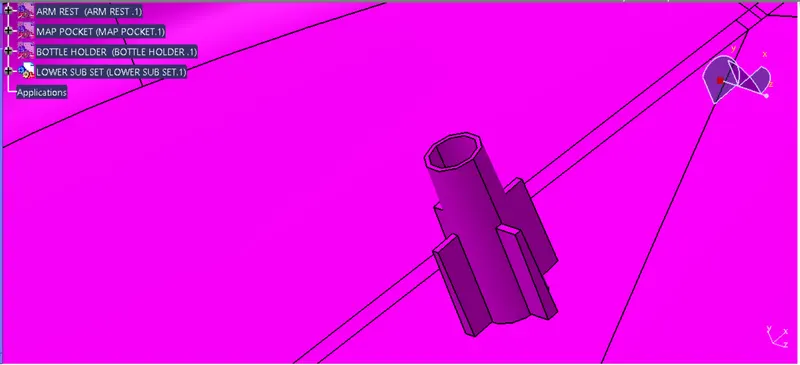
HEAT STAKE:
To draw a heat stake in CATIA V5, you can follow these steps:
Open a new CATIA V5 part file and create a new sketch.
Use the Line command to draw the shape of the heat stake. You can use a polygon or a rectangle shape, depending on your requirements. Ensure that the shape has an interior space where the material will melt and form the stake.
Draw a small circle at the center of the shape using the Circle command. This circle will be used to define the location of the heat stake.
Use the Pad command to extrude the shape to the desired height.
Create a new sketch on the top face of the heat stake and draw a circle at the center of the top face.
Use the Pad command to extrude the circle to the desired height, creating a post on top of the heat stake.
Create a new sketch on the top face of the post and use the Line command to draw the outline of the top of the post.
Use the Trim command to trim the excess lines of the outline and create a closed profile.
Use the Pad command to extrude the profile to the desired height, creating a flat surface on top of the post.
Create a new sketch on the top face of the flat surface and use the Circle command to draw a circle at the center.
Use the Hole command to create a hole in the flat surface. Ensure that the hole size matches the diameter of the heating tip used for the heat stake.
Draft Analysis of Dog House and Heat Stakes
FLANGES:
To draw a flange in CATIA V5, you can follow these steps:
Open a new CATIA V5 part file and create a new sketch.Use the Line command to draw the profile of the flange. The profile should be in the form of a closed loop that represents the outer boundary of the flange.Use the Offset command to create an offset copy of the profile. This offset will represent the inner boundary of the flange.Use the Pad command to extrude the outer profile to the desired height.
Use the Pocket command to remove material from the center of the flange by extruding the inner profile to the desired depth. This will create a hollow flange with a wall thickness equal to the distance between the outer and inner profiles.Use the Fillet command to add fillets to the inside and outside edges of the flange, creating a smooth transition between the different surfaces.Use the Chamfer command to add chamfers to the edges of the flange, creating a beveled edge for a better fit with mating parts.Use the Hole command to add any necessary holes to the flange. These holes can be used for fastening the flange to other components or for providing access to the inside of the flange.
Add any necessary details or features to the flange, such as logos, part numbers, or surface textures.
Save the file and export it to the desired format.
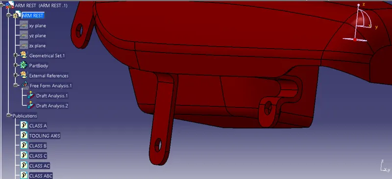
Solid Body Formed
Dtraft Analysis
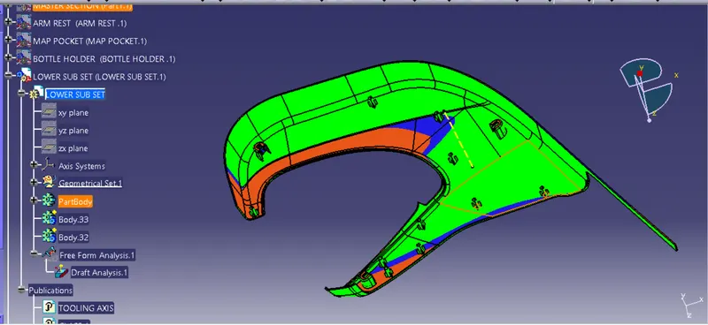
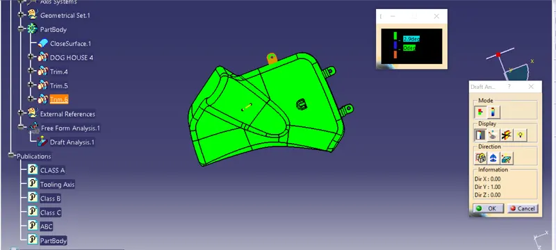
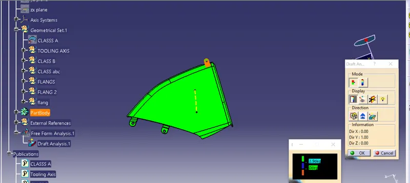
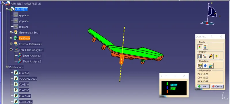
Final Component
PUSH PIN/CLIPS:
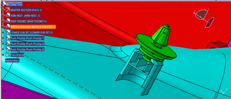
To draw a push pin or clip in CATIA V5, you can follow these steps:
Open a new CATIA V5 part file and create a new sketch.
Draw the profile of the push pin or clip using the Line, Circle, or Arc command. Ensure that the profile is in the form of a closed loop.
Use the Pad command to extrude the profile to the desired height.
Create a new sketch on the top face of the push pin or clip.
Draw a circle or rectangle that represents the shape of the head of the push pin or clip.
Use the Pad command to extrude the head shape to the desired height.
Create a new sketch on the top face of the head of the push pin or clip.
Use the Circle or Rectangle command to draw the shape of the retention clip. The retention clip is the part of the push pin or clip that holds it in place once it is inserted.
Use the Pocket command to remove the material that is inside the retention clip.
Use the Fillet command to add fillets to the edges of the retention clip to create a smooth transition.
Use the Chamfer command to add chamfers to the edges of the push pin or clip, creating a beveled edge for easy insertion.
Add any necessary details or features to the push pin or clip, such as logos, part numbers, or surface textures.
Save the file and export it to the desired format.
These steps are a basic guideline for drawing a push pin or clip in CATIA V5. You can customize the design based on your specific requirements and preferences.
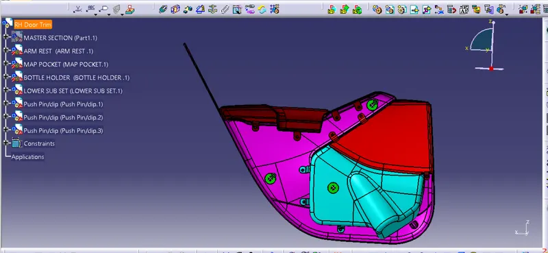
ALL COMPONENTS:
conclusion