DEVELOPMENT OF INTERIOR DOOR TRIM PANEL
DEVELOPMENT OF DOOR TRIM PANEL
Objective:
To develop a door trim panel by using the following steps,
a) Class A surface.
b) Nominal thickness: Refer master sections.
c) Create the mounting features as per design guidelines in the industry and with master sections.
- Map pocket - upper part
- Map pocket - lower part
- Arm rest split parts
- Lower substrate
Introducton:
CATIA v5: CATIA is a multi platform 3D software suite developed by Dassault Systèmes, encompassing CAD, CAM as well as CAE. Dassault is a French engineering giant active in the field of aviation, 3D design, 3D digital mock-ups, and product lifecycle management (PLM) software. CATIA is a solid modelling tool that unites the 3D parametric features with 2D tools and also addresses every design-to-manufacturing process. In addition to creating solid models and assemblies, CATIA also provides generating orthographic, section, auxiliary, isometric or detailed 2D drawing views. It is also possible to generate model dimensions and create reference dimensions in the drawing views. The bi-directionally associative property of CATIA ensures that the modifications made in the model are reflected in the drawing views and vice-versa.
Door tri panel: the door trims are the interior parts that contain the most controls and decorative parts. As such, there is a necessity for balancing gap between parts, as well as an overall sense of unity between the numerous parts.
Procedure:-
CLASS A SURFFACE:-
The class A surface is the one where the customer view the component ,it should be attractive,aesthetic and it doesn't contains any engineering operations.This A surface are created by the styling team.
CLASS B SURFACE:-
The class b surface is created with reference to A surface which is offseted to distance which is measured in master section.The class B surface is the one where all the engineering features will be created.The b surface of the component are created.
C SURFACE :-
The c surface is created for a component by creating the boundary and sweep the curve with reference to the surface make sure to make a draft angle,mostly the c surface is perpendicular to the A surface .The c surface should be attached to the A surface which should be trimmed with B surface.
DRAFT ANALYSIS:-
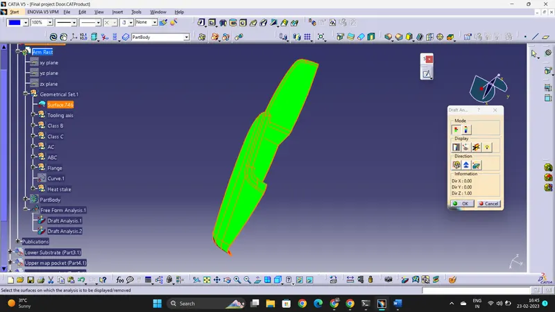
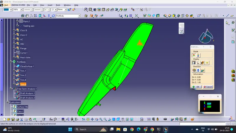
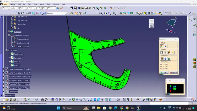
The draft analysis must be done on the component in order to check the draft angle provided for the coomponent. The advisable value for the draft angle is 0.5 - 3 deg which is the nominal value for the draft iin plastic component,the draft analysis done on the component on the axis where the component is moulded.The drafts are vvery essential for the component manufacturing,the drafts are provided on all the engineering features.
Draft angle:
Tooling must be cleared for easy ejection of the component, from the core cavity. In order to clear tooling certain value of draft is given to the component. Minimum of 2-3deg is provides on all plastic components.
DRAFT ANGLE=2-3 DEGREE
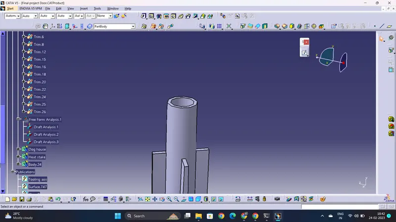
HEAT STAKES:-
The heat stakes are the structures which are used for plastic welding.This is of permanant joint by using controlled melting.Heated thermal tip is used for this process,which is easy method of joining.The draft angle used for the heat stakes is 0.5 deg.this image shows the heat stake with reference to the master section.
RIBS:-
The ribs are supporting structures which gives strength to the thin surface.It should be connected to other structural features.The draft angle for the rib is 0.5 deg,advisable fillet radius is 0.25-1 mm.The design guideline for the rib creation is shown below.
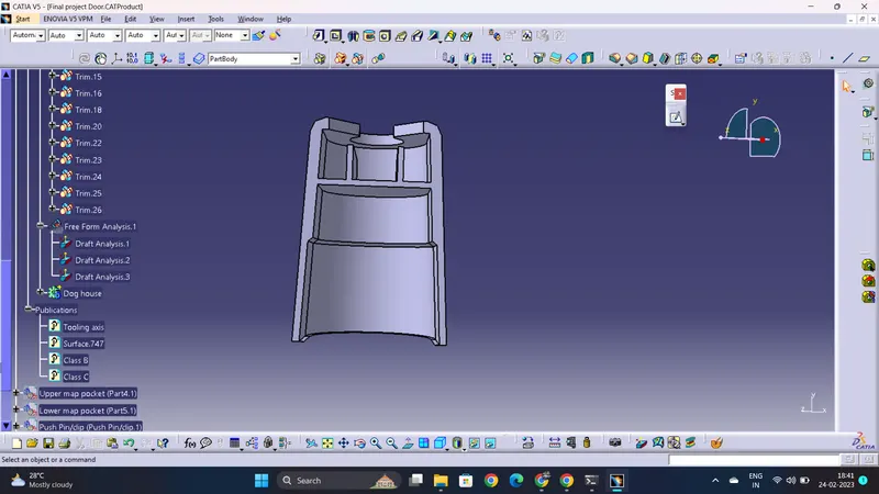
DOG HOUSE:-
The dog house is the structure to have the screw boss/push clips on it.The dog house is used for the screw boss where we needed increased height.The c surface of the dog house should be 40% of wall thickness.The structure is attached to the component.The dog house is used to avoid sink marks.
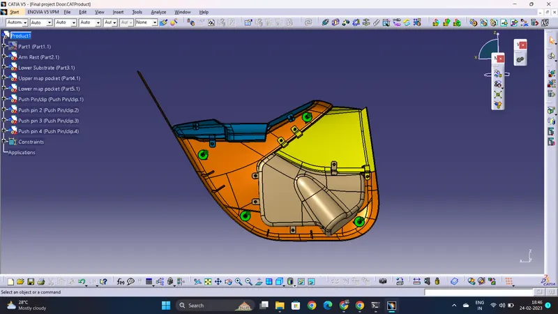
PUSH PIN:-
The push pins are used for fastening or joining two objects which is made up of plastic.The below image shows the push pin.The push pins are created by extracting the given part body and make them a solid body.
Arm rest :-
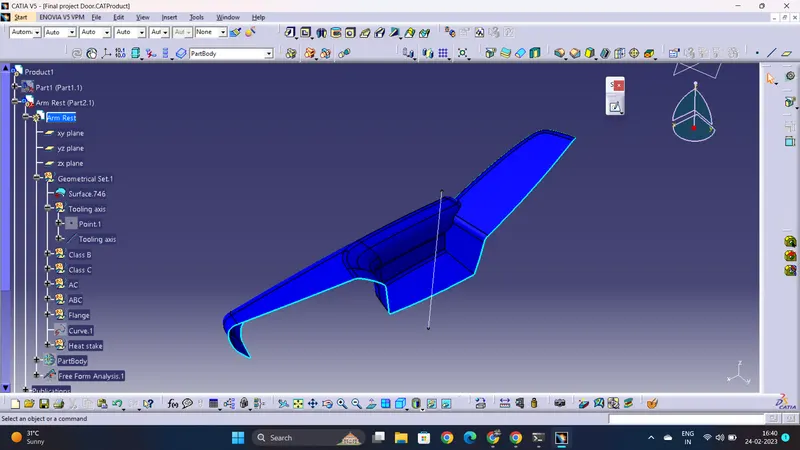
Step 1:- Creating a tooling axis for the component.
Step 2:- Perform Draft analysis to the Class A surface.
Step 3:- Creating Class B surface to the component.
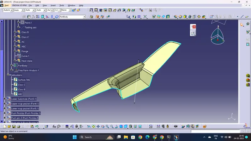
Step 4:- Creating Class C surface to the component.
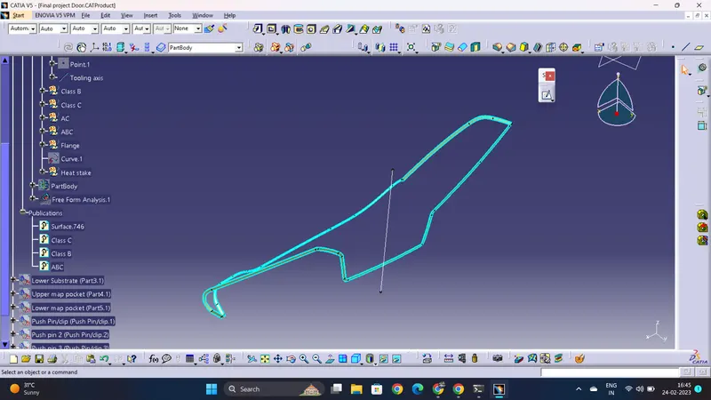
Step 5:- Join the Class A, class B and Class C Surfaces.
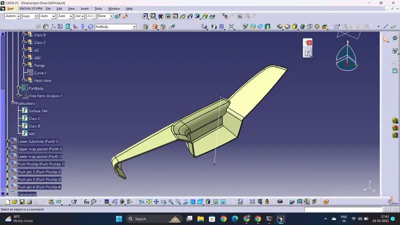
Step 6:- Create the Solid component in the part design work bench.
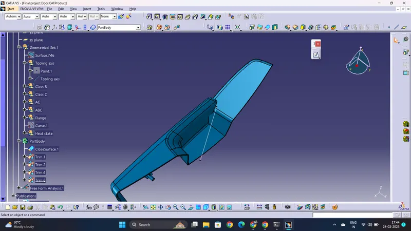
Step 7:- Performing Draft analysis to the solid component.
Lower substrate:-
Step 1:- Creating a tooling axis for the component.
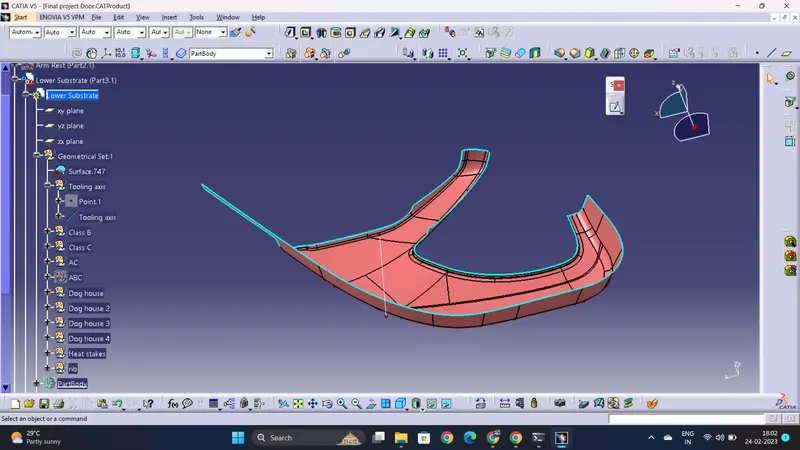
Step 2:- Perform Draft analysis to the Class A surface.
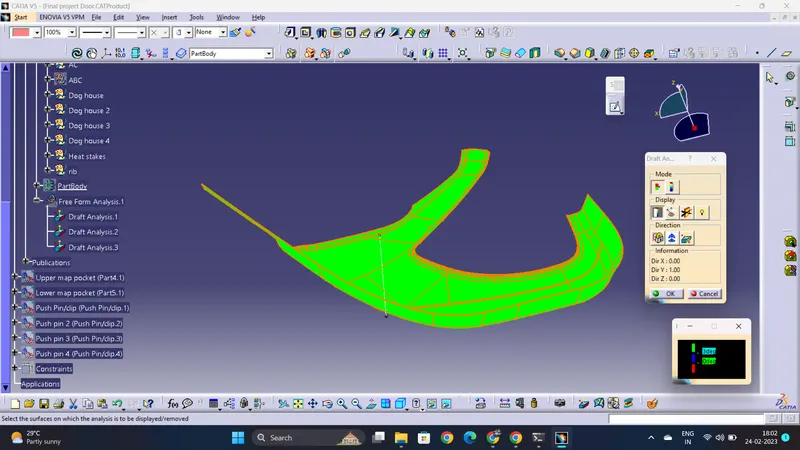
Step 3:- Creating Class B surface to the component.
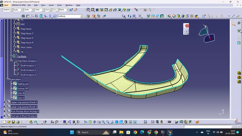
Step 4:- Creating Class C surface to the component.
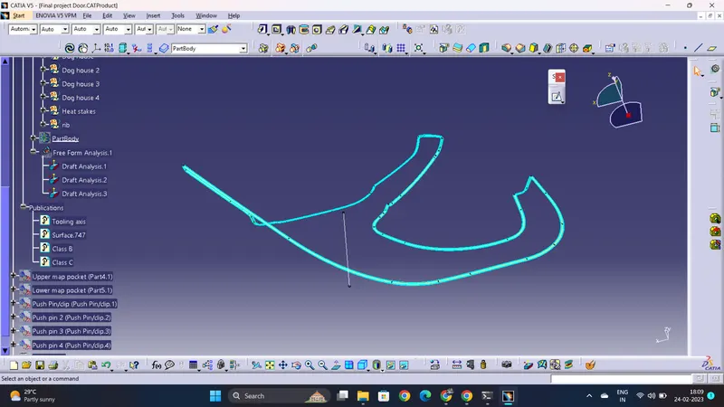
Step 5:- Join the Class A, class B and Class C Surfaces.
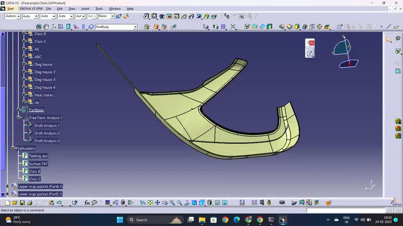
Step 6:- Create the Solid component in the part design work bench.
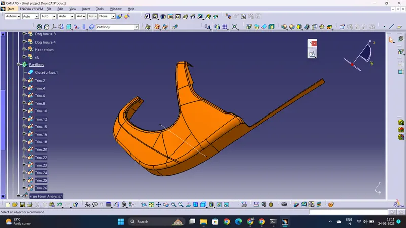
Step 7:- Performing Draft analysis to the solid component.
Upper Map pocket:-
Step 1:- Creating a tooling axis for the component.
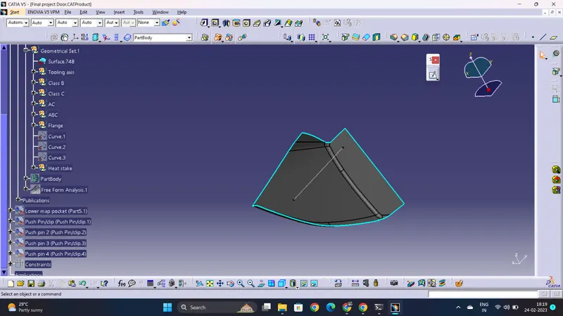
Step 2:- Perform Draft analysis to the Class A surface.
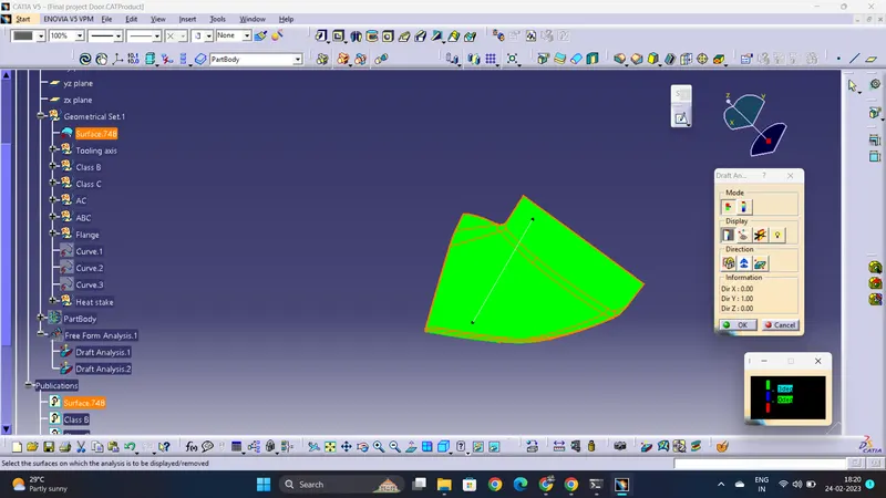
Step 3:- Creating Class B surface to the component.
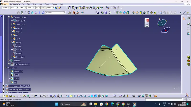
Step 4:- Creating Class C surface to the component.
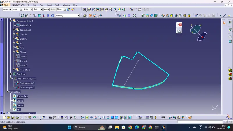
Step 5:- Join the Class A, class B and Class C Surfaces.
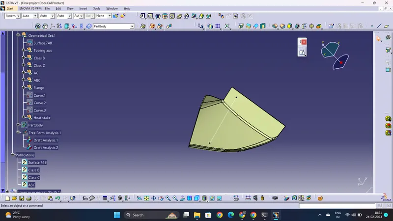
Step 6:- Create the Solid component in the part design work bench.
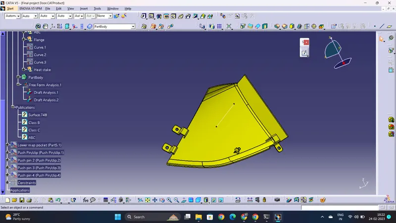
Step 7:- Performing Draft analysis to the solid component.
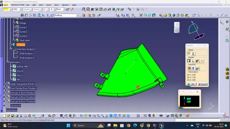
Lower Map pocket:-
Step 1:- Creating a tooling axis for the component.
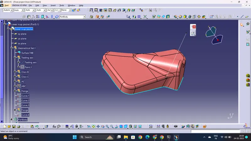
Step 2:- Perform Draft analysis to the Class A surface.
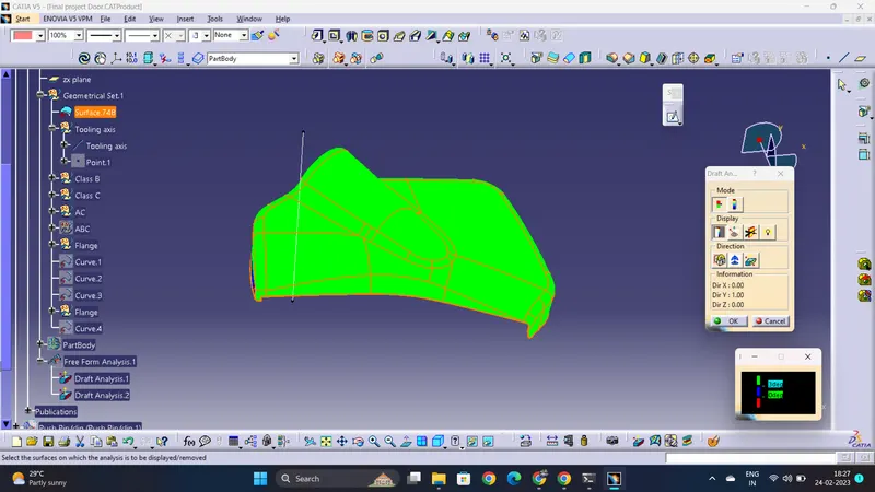
Step 3:- Creating Class B surface to the component.
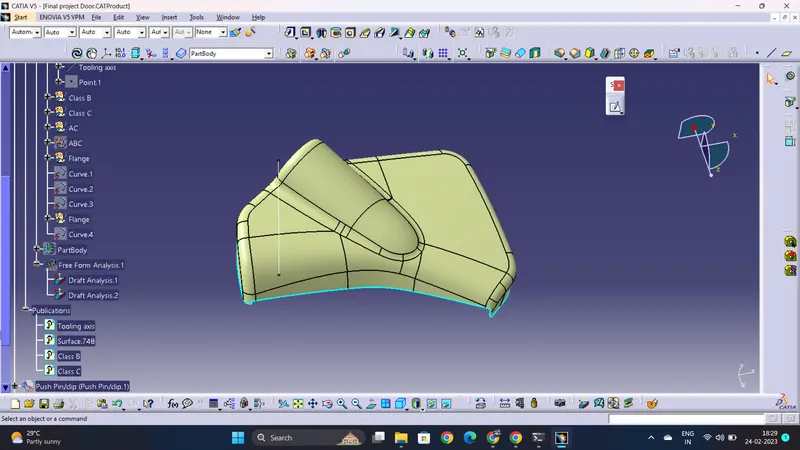
Step 4:- Creating Class C surface to the component.
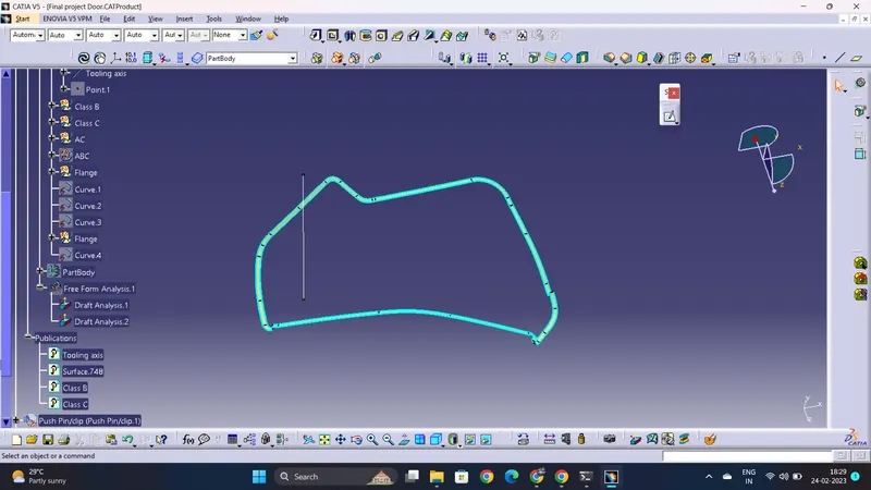
Step 5:- Join the Class A, class B and Class C Surfaces.
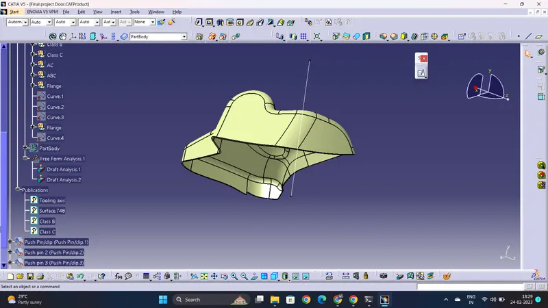
Step 6:- Create the Solid component in the part design work bench.
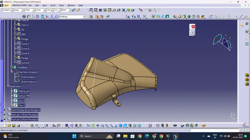
Step 7:- Performing Draft analysis to the solid component.
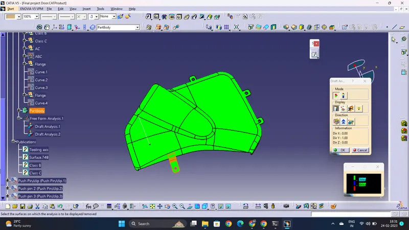
Design of the Dog house as per the dimensions:-
Design of the heat stake as per the dimensions:-
Assembly of the Door Trim with the push pins:-
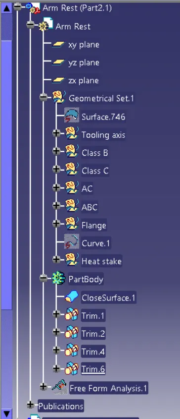
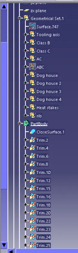
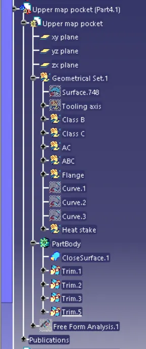
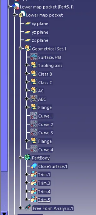
Tree Structure:-
arm rest:-
Lower substrate:-
Upper map Pocket:-
Lower map Pocket:-
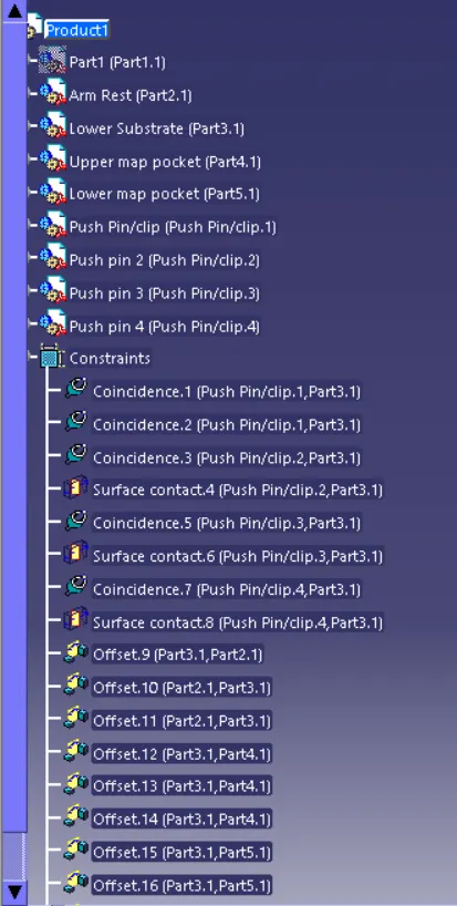
Product Tree structure:-