Design of backdoor
BACK DOOR ASSEMBLY
OBJECTIVE : The objective of the project is to design and developed the back door assembly by considering the methodology and as per standerds. In the project we will going to develop inner panel, outer upper and outer lower panel , embos for the safty and mounting of reinforcement. We will develop the reinforcment fas per requirment.
COMPENENTS TO BE DESIGN
- Outer panel upper
- Outer panel lower
- inner panel with required embosis
- Reinforcement for the Hings, Gas stay, Wiper motor, and stricker
The steps we will follow to develop the back door model:
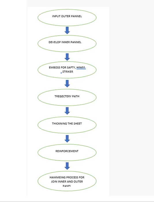
Befor going to the project first we will see how the OEM companies or industries are working with sheet metal , how they wil cut and joint the final product, below mention details will help us to understand the manufacturing process in industry :
The manufacturing process followed in industry for producing final product of sheet metal are mention below-
1)Deep drawing
2)Stamping
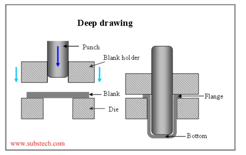
Deep Drawing:
Deep drawing is a sheet metal forming process in which a sheet metal blank is radially drawn into a forming die by the mechanical action of a punch. It is thus a shape transformation process with material retention. The process is considered "deep" drawing when the depth of the drawn part exceeds its diameter.
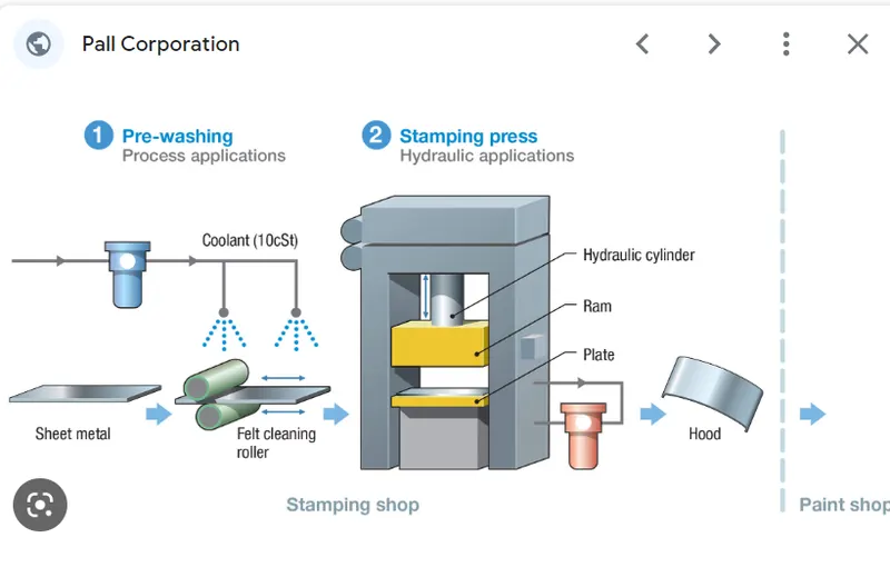
Stamping:
The process of turning sheets of metal into a useful part or component is called sheet metal stamping. The metal is fed into a press, where the stamping tool, also known as a die, creates the desired shape. The die is pressed into or through the metal with tremendous force.
Joining Methodes for Sheet metal production:
- Mechanical Joint
- Rivet Joints.
- Clinching Joint.
- Welding Joint.
- Folding / TAB Sheet Metal Joints.
- Adhesive Bonding.
- Brazing Joint
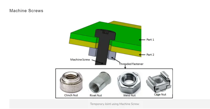
Mechanical joint:
Mechanical joint means that assemble and joining sheet metal pieces together with some hardware or fasteners such as screws, bolts, or nuts. Mechanical joining is the ideal solution for a metal fabrication strategy as it provides simplicity and flexibility. That allows you to be able to reassemble the products or replace the parts or accessories inside the products since the fasteners you are utilizing for the installation are removable.
Welding Joint:
Welding is a popular sheet metal joint method that is widely used, not only that, it’s also traditional that was used several hundred years ago. Most metal products fabricated in the industry apply welding joints. One of the reasons why welding is widely applied is that metal pieces with welding joints can achieve their larger sizes and not influence their properties.
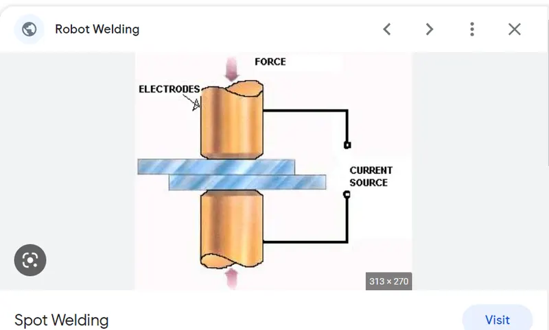
Folding Joint (Hamming):
Folding joining is performed without any fastener and additional accessories, so it’s a cost-effective method for making sheet metal joints. What you only need to do is to place the metal pieces on the bending machines. The edges of the two pieces of sheet metal are bent and folded, they buckle and clamp each other together.
This joining method is more simple and convenient than other types, it can quickly achieve assembly. However, it doesn’t ensure perfect positioning that needs some additional auxiliary manners to complete. Folding joining is suitable for metal without fragility such as aluminum, copper, soft steel, etc.
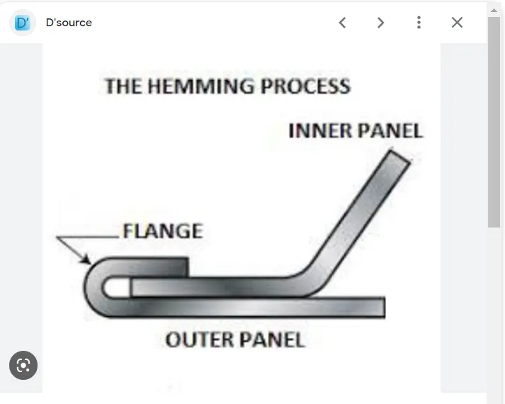
Revit Joint:
Applying the rivet joining process also has a long history. It became a main part of the modern assembly, as it’s widely used in various applications, such as metal tools, constructions, cars, and so on. The cost of this procession is cheaper than welding, but it comes with durability and strength that is just a little lower than welding, though, assemblies with this sheet metal joining technique get a more robust structure when it’s under pressure and at varying temperatures. The Eiffel tower and other symbolic buildings were built with numerous rivets.
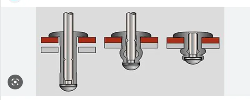
Brazing Joint:
Applying the rivet joining process also has a long history. It became a main part of the modern assembly, as it’s widely used in various applications, such as metal tools, constructions, cars, and so on. The cost of this procession is cheaper than welding, but it comes with durability and strength that is just a little lower than welding, though, assemblies with this sheet metal joining technique get a more robust structure when it’s under pressure and at varying temperatures. The Eiffel tower and other symbolic buildings were built with numerous rivets.
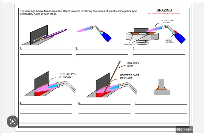
Clinching Joint:
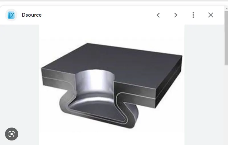
Clinching joint is a permanent joining process that applies the mutual fixation of deformation (looks like a button) between two or more metal sheets to clamp each other together. This method utilizes a cold-forming process, it’s excellent for the application of joining different thicknesses and types of metal. Although the operation is simple, it’s not suitable for the metal products that need to be disassembled in the future.
Adhesive Joint:
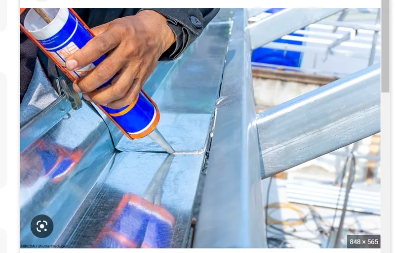
This type of sheet metal joining techniques is performed by using adhesive bonding between two metal sheets. The assembled products can be disassembled by chemical solvents. For adhesive joints, pressure needs to be applied to enhance the bonding strength after the adhesives are placed on the sheet surfaces.
BACK DOOR
Backdoor which is also called rear door/tailgate/trunk are one of the type of door of the vehicle which are located next to the passanger seat which provides access to the luggage compartment. In the most of the cars, these back door are operated with the help of gas stay which in turn reduces the effort required to lift the door.
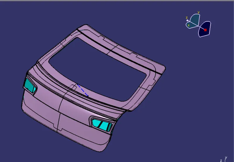
The back door is a assembly which contain outer panel, inner panel, hings for opening and closing, gastay, and striker. We will see one by one for each component how to design and what all considration we need to follow.
Below images shows the back door assembly:
OUTER PANEL:
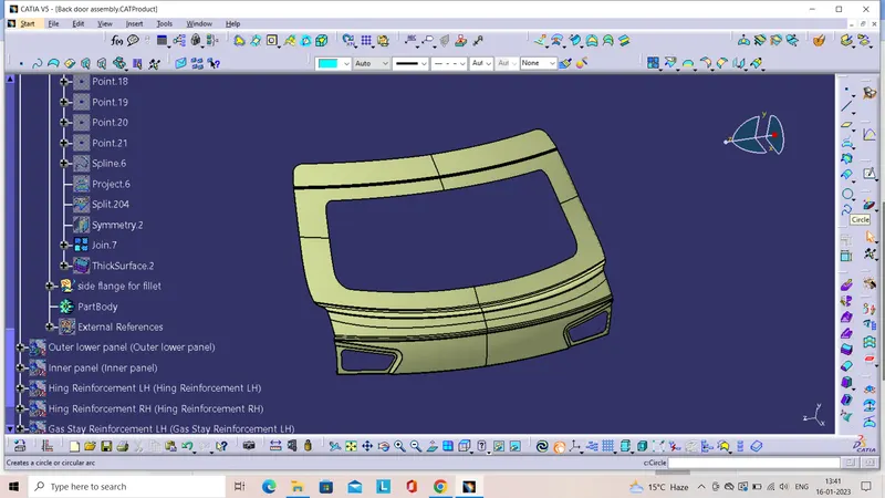
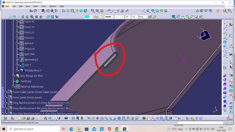
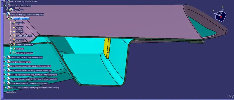
Outer Panel of a back door is the outer surafce of the back door, which is directly visible to the human. This surface is a austhetic surface we should not do any mounting holes welding or any type of bending or punching process, because the suface will visible to the customer. In the ourter panel hemming operation will do to attached with the inner panel.
Below image show the outer panel for the designed back door with haemming operation:
Hemming operation on outer panel
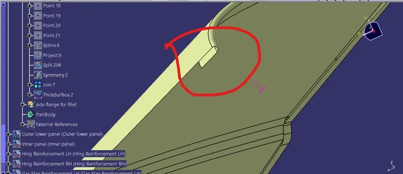
Thicken outer surafce with hemming
Inner panel :
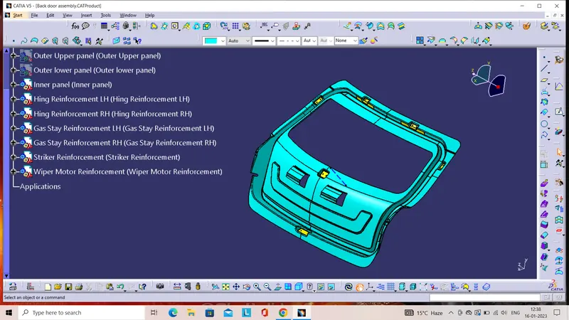
Inner panel is the portion of the back door where all the mounting component are attahed. The nner panel contain sealing flange which is helps to give the air tight fitting to the back door, so that the forigen particales aur liquid things will not allow to entered in the luggage compartment.The component attached to the inner panel are hings , gas stay, wiper motor, striker etc as per requirement.
In this project, we consider the sealing flange height is 30mm and the draft angle is 10 degree, which helps to easy way for manufacturing. The thickness of the inner panel consider 0.75 mm which is the standar thickness consideration for sheet metal design.
The below images shows the inner panel for this project :
Hings :
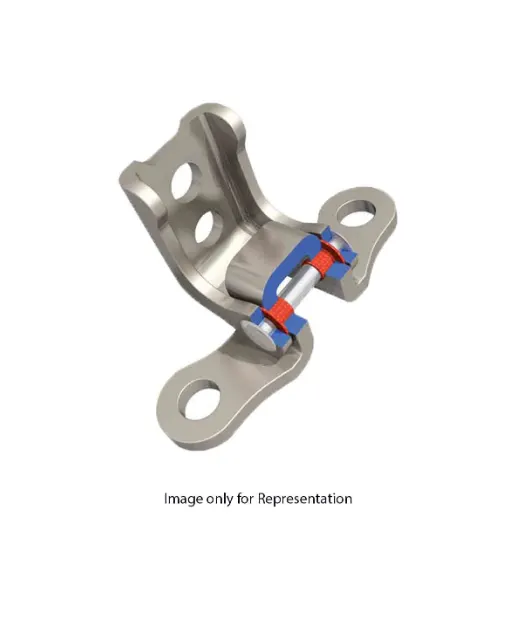
Hings is the assembly component of the back door, it's help the door to get rotation movement whit the specifide roational axis. It is mounter on the top of the back door and atteched with the car body.
Below image shows the hing of the back door:
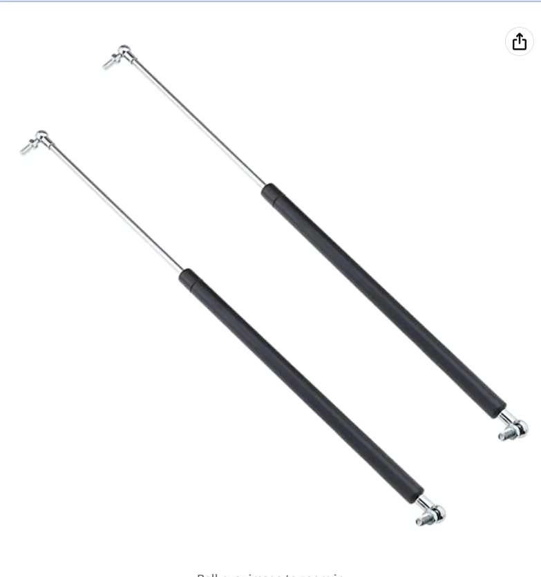
Gas stay :
Gas springs are designed in a similar fashion to shock absorber struts. They are made up of a chamber tube, piston, piston rod and end fittings. The chamber contains highly pressurised nitrogen gas which forces the piston rod to extend
Striker :
The tailgate striker latches allows the tailgate to latch to the striker bolts on the left and right side of the truck bed when closed and then open in operation of the tail gate handle. It is also where the tailgate cables are attached to prevent the tailgate from falling completely when opened.
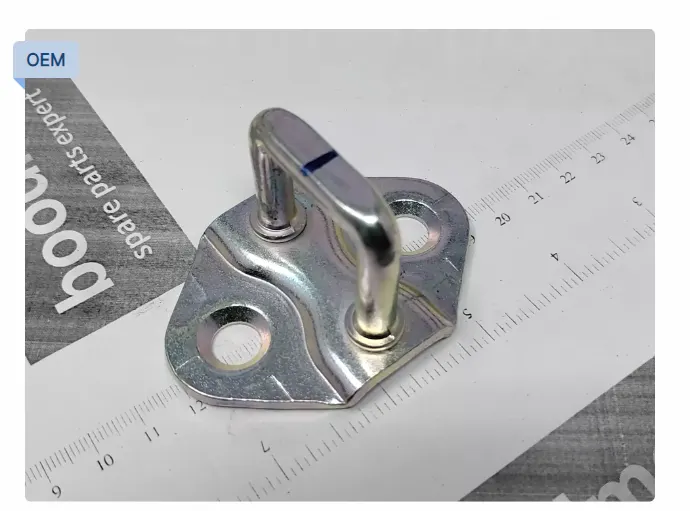
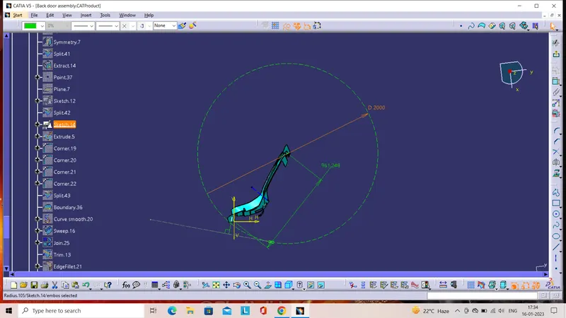
The position of the striker is very importent, if the tailgate striker position is not match with the design standared the it will not heat the latch at the correct position and door will not get locked. The striker is follow the tragectory path to get sitted in the correct position of the latch. The striker is perpendiculer to the trajectory path which is the door opening and closing path also.
Below image show the striker position with trajectory path :
The Process and steps we done in this project for developing final model:
Inner panel
First dowloaded the class A surface then checked the surface is thickning or not , if its not thicking we need to revert the same with the class A surafce engineer. Next we have to created inner panel with the sealing flange. For creating sealing flange we have to extract and offset the class a suraface at specific distance , as for this project there is no any master section provided , so i had offset 30 mm from the outer panel(class A) .
After offseting at 30 mm we need to use parallel command to creat a cuve at a distance of 30-50 mm and then fron that curve we will again creating another curve at the distance of 30mm for creating sealing flange end surface. Once the curve is creadted we need to splite the surface by using splite command.
Next we have to creat side surafce of the sealing flange by using sweep command and we have to give the draft angle minimum 7 degree with the reference of tooling axis. At the end we will get he sealing flange side surface.
For creting inner panel, we have to extract the outer upper panel and outer lower panel surface which is required, the after performing the same parallel, split and sweep command we will get the inner panel with sealing flange.
After that we need to give the fillted as per requirement where ever needed. Next we have to focus on emboses. I this project we created embos for hings mounting , gas stay mounting, wiper mounting , striker mounting and the embose we creted for reduicing the impact force from the back.
Once the emboses will get created we need to creat flnage for mastic which help to attached the inner panel and outer panel at the visualizing area, because we can't do the spot welding at the visualizing area of the outer surface. Then final we have to do thicken of our inner panel wit 0.75 mm thickness.
Outer upper panel :
For outer upper panel we need to check the surface by joining operation with tolorence 0.001mm. The surface which is not geting join with the specified tolorence we need to remove that particular surface and recreat the surafce by using different operation and command. One the final joint outer upper panel develped we need to thickne the surface innward with 0.75 mm thickness.
Outer Lower panel :
For the outer lower panel we need to follow the same procedure as we done in outer upper panel and then we need to do final joint and thicken it with 0.75mm thickness inward direction.
Reinforcements :
Once the inner panel got thicken at required thickness, we nned to developed the reinforcement. The emboses we created for the hings , gas stay, wiper motor, and striker, we need to extract the surface which we need to use for creating reinforcement.
Once the surface is extrated, need to do splite operation we remove the unwanted suraface. One the required shape is developed we will do the thikining of the reinforcement at 1.5mm thickness.
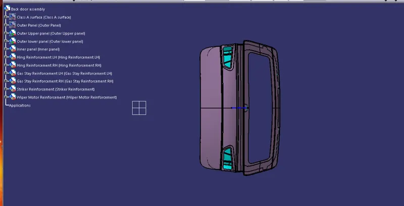
Then finally we will assembly the inner panel outer upper panel , outer lower panel and the reinforcement to see the final model of the Back door assembly.
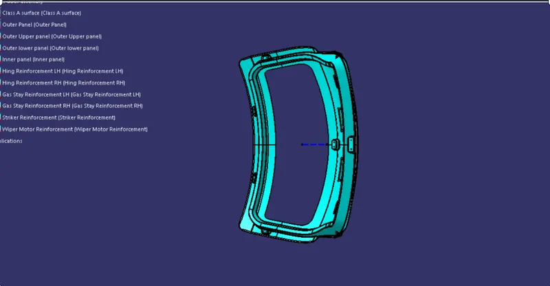
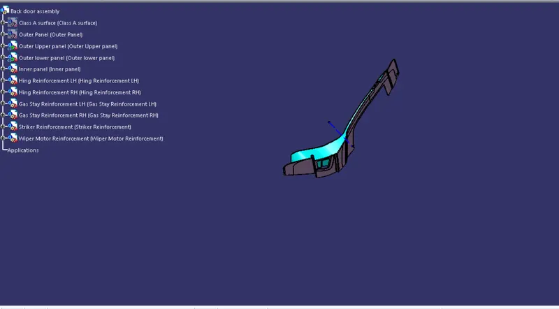
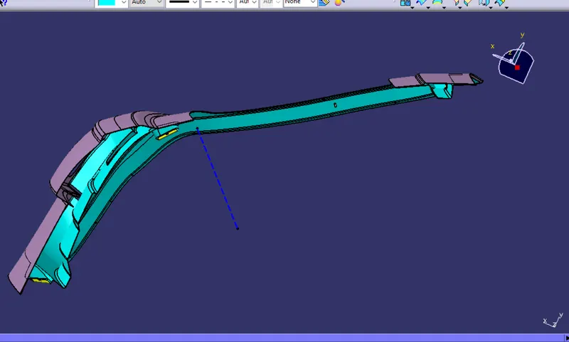
Below is the final model images at different position :
CONCLUSION :
In this project we learn how to develop the back door assembly by using class A surface. some different operation also got idea if the one particular operation is not work on time. We learn about the use of emboses and trajectory path and there principle.