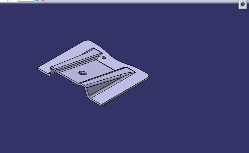
Week 8 - Challenge 1 - Base Bracket Design
REPORT
PLASTIC PRODUCT DESIGN
BASE BRACKET
Objective: Create the platic part name as base bracket from the given input class A surface, will do the draft analysis and creat the tooling axis for the base bracket.
Procedure: For developing the plastic product from the given class A surface, we need to follow the following steps wich the shown blow in chart-
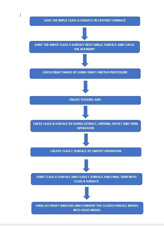
Daft analysis: It is very important to give draft angle to the plastic product to avoid the damage or defective product output. The draft angle using in industries is 3 degree.
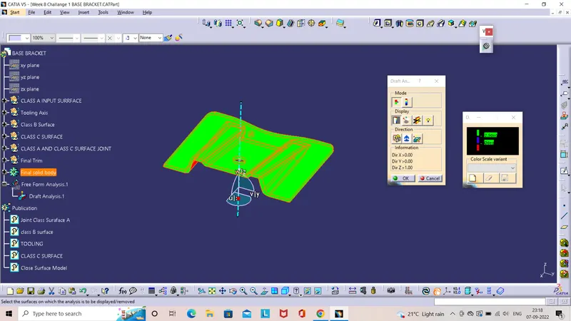
In draft analysis, first we have to set the tooling axis amd by taking the reference of tooling axis we have to do the draft analysis of the model. Below picture show the draft analysis of the model.The green colour indicate that the model is design as per the manufacturing standard.
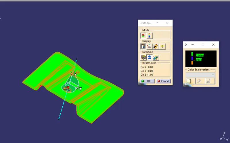
Tooling Axis: Tooling axis is very import for manufacturing the product, its set the movement of direction for core and cavity in moulding machine. When we will design any plastic model we have to creat the tooling axis .There are different way for creating tooling axis which is mention below.
- Normal X, Y, Z axis
- Point and direction
- Normal to surface
- Side Core axis(if required)
- Bisecting Methode.
For this model i use Point and direction methode for creating tooling axis. First i analys the coorrect surface for creating tooling axis, as its showing in the above pic, i choose center surface.First i extract the surface then created the point by using middle to surface option. Once the point is created i creat the line by using point and direction option and created the line and did some changes in thickness, colour etc to highlight the tooling axis.
B Surface: The B surface can be created in two way, either multiple offset at given distance or in single offset. once the offset will finish, need to observe the surface which is not get offset. The portion which is not get offset we need to creat the surface by manually (extrapolte, trimmed, multisection etc).
C Surface: The C surface help to connect the surface A and surface B which develop close surface.The surface is creat with reference to the class A surafce and tooling direction. By taking the boundary reference of class A surface n swept the curve with minimum 3 degree alonge with tooling axis.
Once the C surface created we need to join Class A suarface and the class C surface. At the end the B suface n C surface the to join by using trimmed operation.
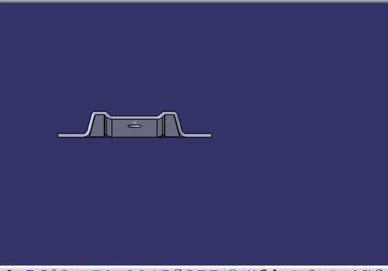
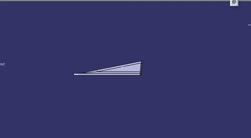
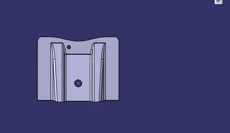
Final Solid Body: Once the close surafce is developed after doing trimmed operation, need to enter in part work bench and by using close surafce option we should convert the close surafce into sold body. once the solid body created we need to do final draft analysis, by using previouse procedure.