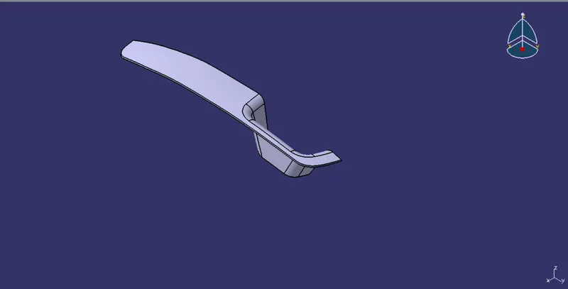
Week 8 - Challenge 2 - Switch Bezel Design
REPORT
PLASTIC PRODUCT DESIGN
SWITCH BEZEL
OBJECTIVE: Developing the switch bezel plast model design by using input class A surface and will perform the draft analysis for the final model.
PROCEDURE: The procedure to follow for developing or design plastic product model by using style surface are mention below:-
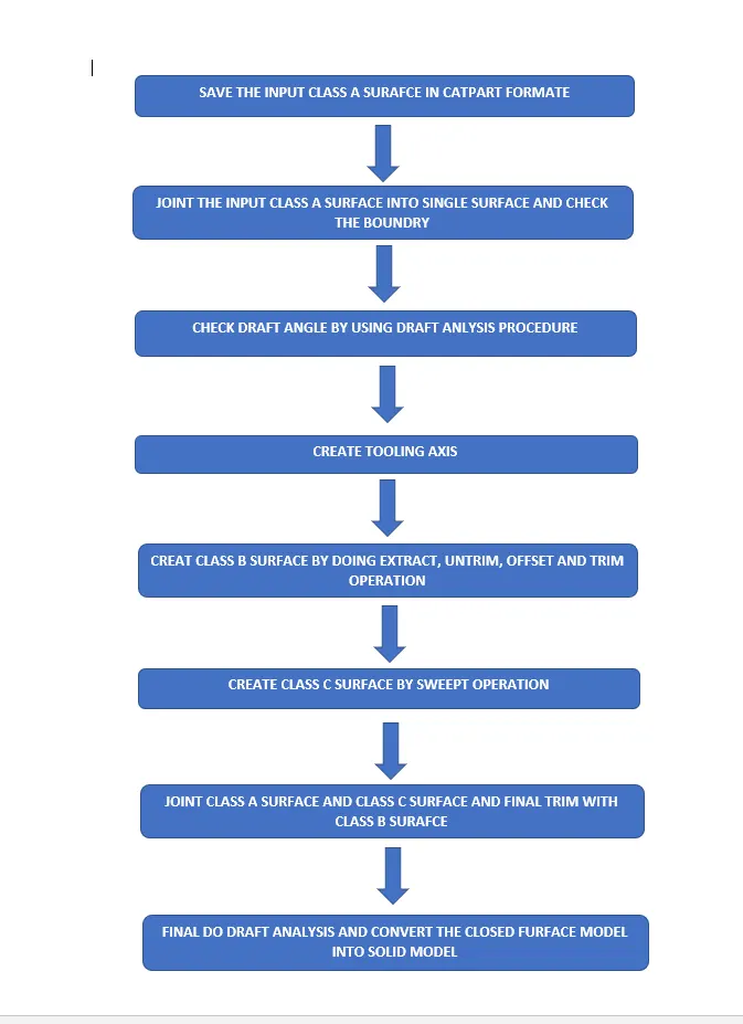
TOOLING AXIS: Tooling axis is the movement direction of mould and cavity, so its very importand to creat the tooling axis for the plastic product model, to analysis the draft angle effect on the product. for this model the tooling axis is created by using normal to surface method.
Types of tooling axis:-
- Normal X,Y,Z axis
- Point and Direction
- Normal to surface
- Side core axis( if required)
- Bisecting Method
first we have to analys the model and find the suitable surface where the tooling axis can creat. Then next exctract the surface and by using normal to surface option in line creation tool, creat the tooling axis for the model.
Once the tooling axis is created we need to do draft analysis for the given input class a surface.
DRAFT ANALYSIS: It is very improtant to give draft angle to the plast product to avoid the damage or defectice product output. The draft angle using in industry is 3 degree.
Drag the compus to the tooling axis and kept in center and then click on the campus icon on draft analysis dialoge box, campus will get active and the drage the campus and kept it alingment to the tooling axis.
Once the campus is alinged with tooling axis, click on the model to do the draft analysis, the model is convert into green colour then its means model is perfect and if its showing red colour the click in reverse option in traft anaalysis dialoge box n then it will convert in green colour.
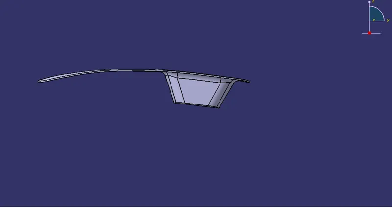
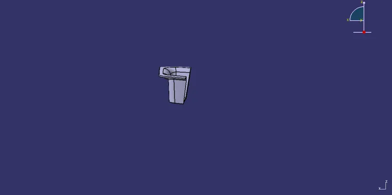
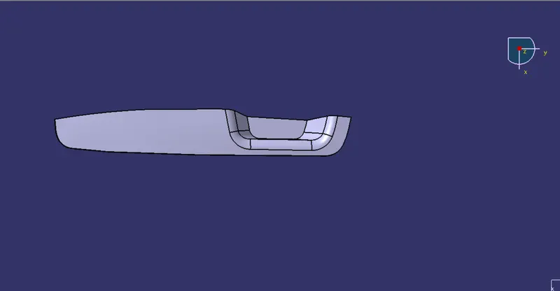
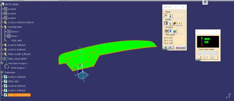
After reverse also colour is in red the its ,indicate the model is not suitable for modling and need to work on surafce angle. Below picture showing the draft analysis for switch Bezzle.
Draft analysis for final close surafe:
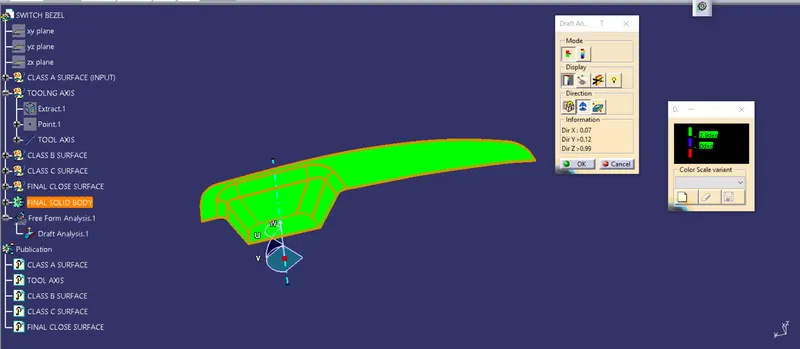
Draft analysis for solid body:
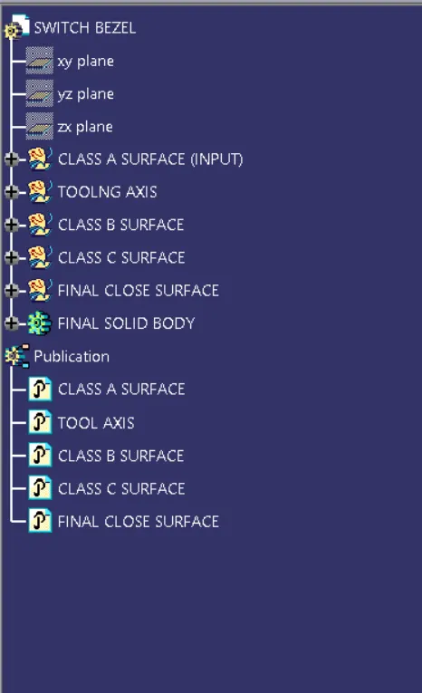
B SURAFCE: Once the draft analysis is over for the class A surface, next step is to creat the B surface. Analysis the class A suarfce if the number of surface is less then proceed with multiple offset or if the class A surface is more surafce wich is difficult to offest one by one then in that stage we have to do offset in single step.
For this model the class A surface is less surface so, multiple offest is use for offsetting the surfac. Once the surface is offset then we have to creat the B surface by using extraplote and trimmed operation.
CLASS C SURFACE: The class C surface help to connect the class A surface and B surface. The C surface is created with reference of class A surface and and tooling axis.When the C surafce is created we have to give the proper angle ,if the draft angle is not given then it will creat problem while moulding the product.
First we have to take the boundary for the class A surafce edges and by using swept commond , the C surface will develop. While developing C surface we need to give proper draft angle to the surface.
Once the C surface created then need to check the proper intersection of C surface and B surface. By joining and trimming of C surface from A surafce and B surface respectively, the final close surafce will develop and then again we have to do the draft analysis fro the close surface.
FINAL SOLID BODY: This is the final stage of the plastic product model, where the final close surface will get converted into a solid body. Once the final close surface is develop then we have to shift to part wokebench fron surface workbench. In part workbench by using close surface commond , the close surface will get convert to solid body.
Once the solid body is created, we have to do the draft analysis for the final solid body.