Design of backdoor
Design of the back door of a car using NX CAD
OBJECTIVE:
To design the back door of the car
To make an inner panel for the back door
make all the necessary re-enforcements
INTRODUCTION:
The back door of a car is use to acess the boot of the car. The back door consists of two or three panels. The outer panels and the inner panel. The inner panel is used for providing strength to the outer panel. The inner panel has a V-Shaped emboss to give it strength. The outer and the inner panel are joined using hem and mastic sealent. The inner panel also has the latch that is used to lock the door. The back door when opened in supported by the gas stay to maintain its position. The door is connected to the roof by sets of two hinges.
The back door can be manually opened or can be powered by a motor.
Expensive cas use powered tailgate
The back door is now made of aluminium by many car manufacturers insted of steel.
Consideration:
The wind screen should give good visibilty.
The door should be strong to sustain the impact during closing.
The door should be thin to maximize the boot/luagage area.
Door should be light weight if manually opened.
DESIGN OF THE BACK DOOR:
A dumb body is provided
Back door inner panel:
Tools and command used:
Sketch
Project curve
Emboss
Trim
Bridge curve
Offset in face
Trough curve mesh
Studio surface
Law extension
Trim curve
Curve length
Sew
Thicken
Mirror geometry
WAVE Linker Geometry
About inner panel:
The inner panel is made of aluminium
The inner panel has the thickness of 0.75 mm
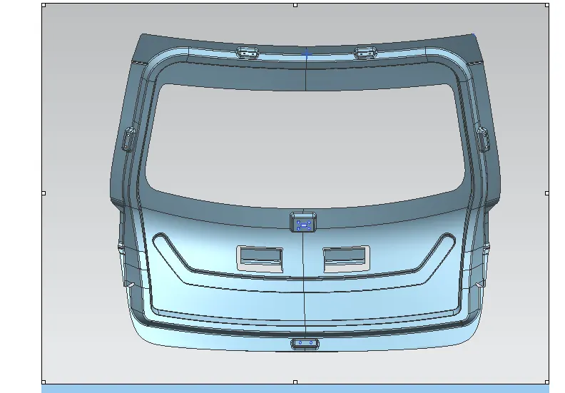
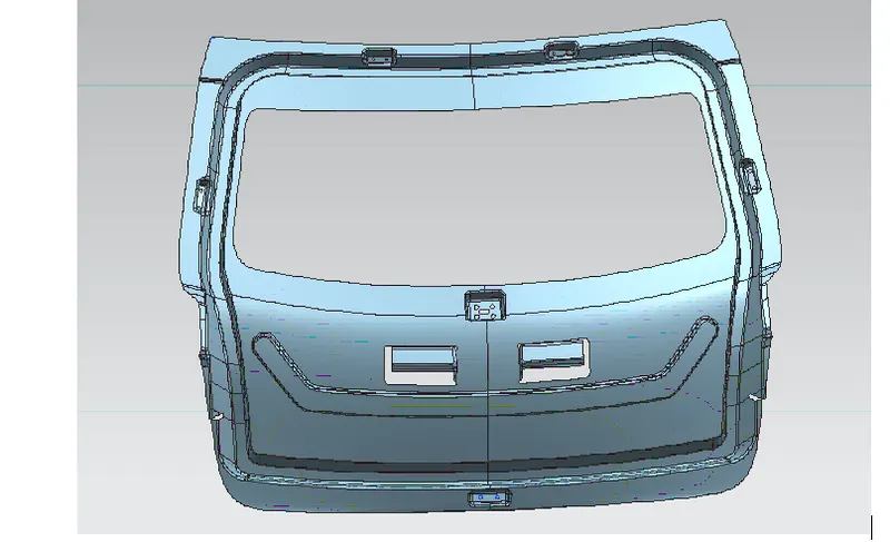
The inner panel has a V-shaped emboss. The v-shaped emboss is used for providing the strength to the inner panel during impact.
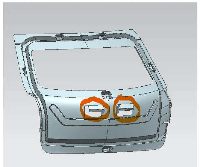
The inner panel also consists of mastic support region which is used to put mastic between outer and inner panel to prevent vibration.
The outer panel is hemmed on the inner panel.
The inner panel has hinge mounting area, gas stay mounting area, Latch mounting area and wiper motor mounting area.
Re-enforcements are provided on mounting area.
The inner panel have holes for the tail lights.
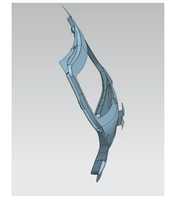
The inner panel is designed to provide enough boot space.
The inner panel has a sealing flange which seals the boot with help of a rubber seal.
Design Methodology:
The given body is offset to 25 mm by using offset command and a sealing flange is made.
Then the windscreen area is created and the lower portion of the inner panel is created.
V-embosses are made using sketch, project curve and emboss command.
The panel is sewed using sew command.
The panel is then mirrored on z-axis and sewed
The inner panel is then thickned uning the thicken command
Inner panel images:
Inner panel mastic support:
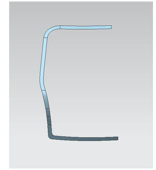
Sealing flange:
Outer Panel:
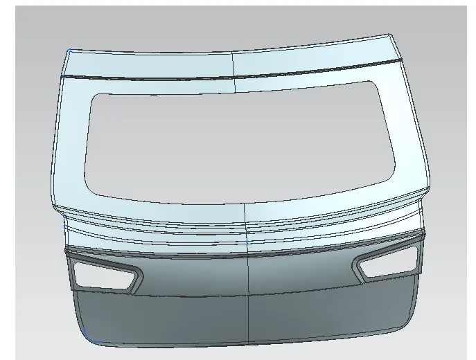
NOTE: The outer panel has two parts lower (Green) and upper (Blue) part, both are designed with the same method. Both the panels have same thickness.
Tools and command used:
Offset
Spline
Sketch
Project curve
Trim
Law extension
Extend sheet
Sew
Thicken
Swept
Through curve mesh
Inersection curve
Datum
WAVE Linker Geometry
About outer panel:
The outer panel is a styling panel.
This panel is 0.75 mm thick
This panel is hemmed on the inner panel
Design methodology:
The outer panel is first offset
The offset surface is trimmed to required surface to make hem
Bridge curve is made at the start
Swept is used to make the bend surface between the two surfaces
The finished panel is sewed
The panel is mirrored along z-axis.
The panel is sewes and thickened to 0.75mm
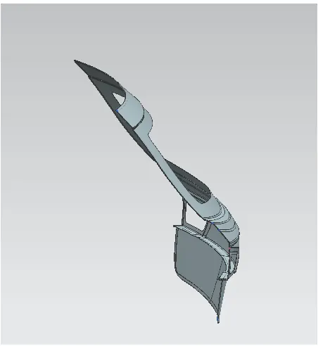
Outer panel images:
Re-enforcements:
Tools and command used:
WAVE Linker Geometry
Offset surface
offset curve in face
Trim curve
bridge curve
Through curves
Thicken
Mirror geomerty
sew
About Re-enforcements:
The re-enforcements are provided to strenthen the weaker areas after drilling holes.
The thickness of the re-enforcements is 1.5 mm
Design methodology:
All re-enforcements are designed by extarcting the surface by using wave linker geometry and offseting them to a required positions.
Types of re-enforcements:
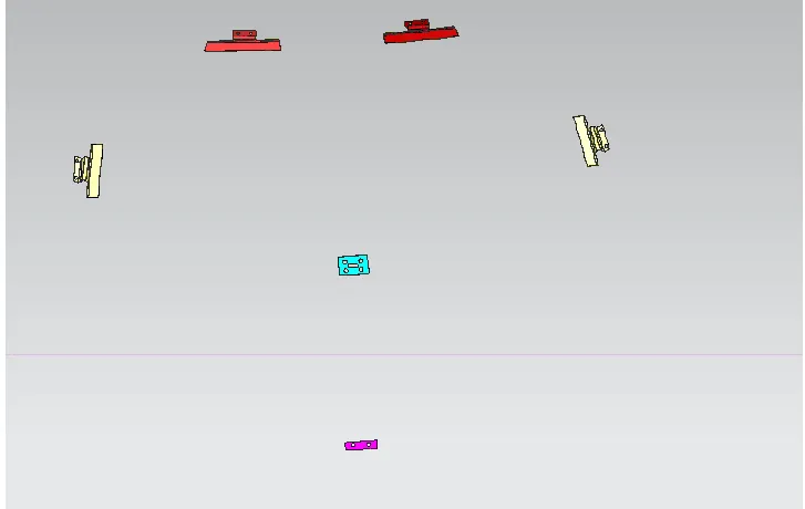
Hinge re-enforcement (Red)
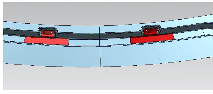
Gas Stay re-enforcements (Yellow)
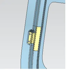
Latch re-enforcements
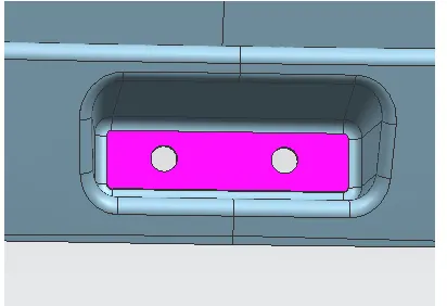
Wiper motor re-enforcements
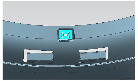
Images:
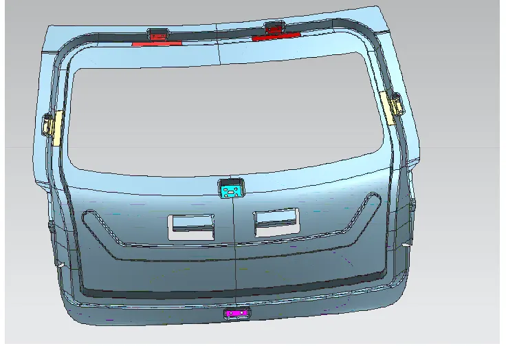
Re-enforcement placement without the inner panel:
Latch placement:
The latch is placed using a reference circle.
A circle is drawn and a surface is made 90 deg to the circle.
Assembly:
Top to down approch is followed in the assembly. The parts are created within the assembly and designed.
Conclusion:
The parts of back door were designed using top to down approch in NX CAD. All the necessary re-enforcements were designed and assembled.