Design of backdoor
TAIL GATE / BACK DOOR DESIGN (BIW) USING SIEMEN NX
OBJECTIVE
The main objective of this project is to learn the Basics of the BIW (Body in white) through designing the Back Door “also referred as Tail Gate” of a car by considering all the Protocols and Standards of BIW Design.
INTRODUCTION
What is BIW?
Body in white (BIW) is the stage in automobile manufacturing in which a car body's frame has been joined together, that is before painting and before the motor, chassis sub-assemblies, or trim (glass, door locks/handles, seats, upholstery, electronics, etc.) have been integrated into the structure. Assembly involves different techniques such as welding (spot, MIG/MAG), riveting, clinching, bonding and laser brazing. Body in white refers to the stage in automotive manufacturing when a car’s sheet metal components are welded together which include:
Hood
Trunk lid
Roof
Front and rear fender
Side wall
Side Doors
Tail Gate (Back Door)
The term BIW derives from manufacturing practices before steel unibody monocoques — when automobile bodies were made by outside firms on a separate chassis with an engine, suspension, and fenders attached .The manufacturers built or purchased wooden bodies (with thin, non-structural metal sheets on the outside) to bolt onto the frame. The bodies were painted white prior to the final colour.
A folk etymology for "body in white" is the appearance of a car body after it is dipped into a white bath of primer (undercoat paint) — despite the primer's actual grey colour. BIW could also refer to when car bodywork would be made of timber - all timber products, furniture, etc., are considered to be "in the white" when at the stage of raw timber before finishing or varnishing.
In car design, the "body in white" phase is where the final contours of the car body are worked out, in preparation for the ordering of the expensive production stamping die. Extensive computer simulations of crash-worthiness, manufacturability, and automotive aerodynamics are required before a clay model from the design studio can be converted into a body in white ready for production
What is a Tail Gate (Back Door)?
The Tail gate or the Back door of a car is the Door at the rear end of the car, which provides access to the luggage compartment. In most of the cars, these back doors are operated with the help of gas stay which in turn reduces the effort required to lift open the door. Some luxury cars have powered backdoor which is driven by an electric motor. This kind of system is also called a powered trunk lid system. The Back door is also responsible for dissipating the force created while rear collisions, away from coming inside the car.
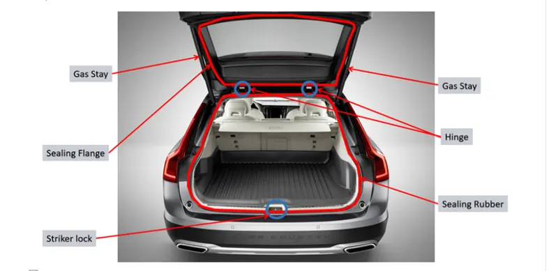
DESCRIPTION
In this project we are going to create the Assembly of a Back Door using previously given styling surface (outer panel surface) as the reference. The software used here to model the Tail gate is Siemens NX
The assembly of Back Door consist of various components such as Outer panel Upper, Outer panel Lower, Inner panel, Hinges, gas stay, Latch and the Reinforcements. Here we are mainly dealing with, the design of inner panel.
For creating a Tail gate, there are several Factors and standards a Design engineer should consider .Some of them are below
Major Factors to Consider
Material selection
Stiffness and strength and weight of the part
Rear visibility criteria
Hinge position
Latch position
Distance from the outer panel to mastic points Should maintained in between 4-6 mm
Drawability ( Minimum 7 degrees open)
Hemming parameters
Holes (to drain the primer from the cavities
1.Material selection
Tail gate BIW is expected to possess a number of significant properties. It must have high tensile strength as well as high stiffness—bending, torsional, static, and dynamic. It must also provide good quality safety both to the car body and to its occupants against crashes of all kinds—front, rear, side, or even rollover, meeting the Federal Motor Vehicle Safety Standard No. 208 [44]. It should also be able to protect occupants from noise, vibration, and/or harshness (NVH) by absorbing or reducing these conditions. Also, it should be easy to weld and form, as well as be highly paintable and easy to design. It should provide a good surface finish that is smooth, and should also be corrosion resistant. Improvement of fuel economy also necessitates the use of lightweight materials in BIW, as it constitutes a significant share of car’s weight; in addition, given environmental concerns in recent times, it is also expected to be recyclable. Given such extensive requirements, only steel and aluminium have been used for making BIW; the former is preferred for its high strength and low cost, while the latter is preferred for its lower density that helps reduce car weight
Here we are assuming Stainless steel as the material for the Designing of Back Door
- Stiffness, strength and weight of the part
As the Back door protects the passengers from rear collisions, it should have enough strength and stiffness .Stiffness, strength and weight of the part depends up on major two factors .The first is the material selection, which is discussed above and the second one is the Design of the part.
A Design engineer can easily increase and reduce the stiffness of the part through his or her designs. The methods of increasing stiffness and strength of the parts are adding Embosses in the models.
Embossing
Sheet metal embossing is a stamping process for producing raised or sunken designs or relief in sheet metal. This process can be made by means of matched male and female roller dies, or by passing sheet or a strip of metal between rolls of the desired pattern .Adding of embosses to a sheet metal part , drastically increase the strength of the part.
- Rear visibility criteria
This criteria deals with the visibility of passengers backwards through the rear wind shield glass.it mainly depends up on the Wind glass area .Here in this case as we already have a styling surface wind already included the wind shield area we need not to worry about the Rear visibility criteria
4.Hinge position
Hinges are the part which helps to open the Back Door to the luggage space. One part of the hinge is connected to the inner panel of the Back Door while the other is connected with the Roof
There are a few things to consider while the positioning of hinges i
The surface where the hinges to be mounted must be flat in order to keep the hinge tightly in touch with the inner panel , otherwise it leads to loosening of the nuts and bolts resulting in NVH ( Noise ,Vibration and Harshness)
Reinforcements must be provided on both hinges .Because in sheet metals adding another solid body or a sheet body on it, will results in decreasing the strength of the part. To overcome this problem Reinforcements are used
The central line or the axis of each hinges must be collinear
- Latch position
Placing Latch/striker is one of the major factors to take care of .As a Latch/striker is separate body and itself reinforcement, there is no need to add extra reinforcements. But like in hinges it’s compulsory to have a flat surface to mount it.
The striker in the Body and the Latch in the back door must be normal to a trajectory path to have a smooth locking and unlocking.
- Distance from the outer panel to mastic points
The Mastic sealant or the Mastic point is an elastic compound that behaves like a rubber. The mastic points are defined on the hood inner panel where the hood can easily deform. They help the hood outer panel to come back to its original shape after it gets deformed .The distance from mastic points to the outer panel must be 2-8 mm
- Hemming parameters
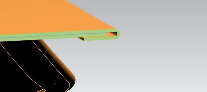
Hemming is a sheet metal forming process in which sheets are joined by bending it usually to 180°. Automotive body panels and automotive parts such as deck-lids, trunk-lids, doors, hoods and tailgates are formed by hemming process.
While hemming the gap between two sheet metals must be in between .2 to .5 mm and the distance bend of the outer sheet metal to the edge of the inner sheet metal must be 2 mm.
- Drawability (Draft Analysis)
To understand what drawability is, first we should know what deep drawing is
Deep drawing
Deep drawing is a sheet metal forming process in which a sheet metal blank is radially drawn into a forming die by the mechanical action of a punch. It is thus a shape transformation process with material retention. The process is considered "deep" drawing when the depth of the drawn part exceeds its diameter. This is achieved by redrawing the part through a series of dies. The flange region (sheet metal in the die shoulder area) experiences a radial drawing stress and a tangential compressive stress due to the material retention property. These compressive stresses (hoop stresses) result in flange wrinkles (wrinkles of the first order). Wrinkles can be prevented by using a blank holder, the function of which is to facilitate controlled material flow into the die radius. The feasibility of this deep drawing is called Drawability.
Draft analysis in Siemen NX is one of the tool used to study the deep drawing feasibility easily through checking draft angle in the various faces .The Designer should Define a tooling direction in-order to check the draft angles
- Holes (to drain the primer from the cavities)
In the inner side of the Tail gate we can see several holes in the hood. Every hole in it has its purposes. Apart from the holes for the fasteners, these holes allow e-coating, surface prep, and primer to drain from the cavities in between the tail gate skin and tail gate skeleton after the chassis is dipped into these during production.
Components to Design
Here in this project we are not creating the hinges as well as the latches. Only we are creating Back Door outer panel, Back Door inner panel, Reinforcements for Hinge, Gas stay and Viper mounts in this case we need to assume the hinge position and hinge axis appropriately.
Back Door outer panel
As we have the styling surface as the reference we need not to work more on the outer panel only need to create the hem flanges after the creation of inner panel.
Here the outer panel of the tailgate consist of two parts which are the Outer panel upper and the Outer panel lower. These two components are joined using the Laser Brazing method
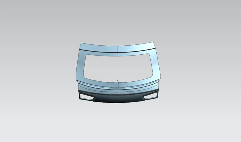
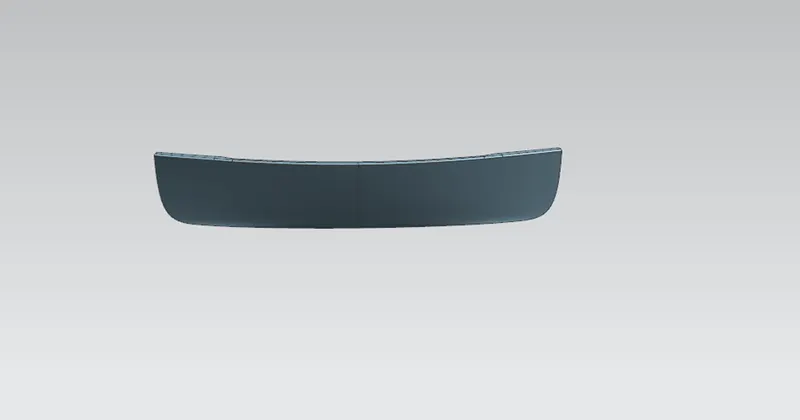
Laser Brazing
Joining methods, in which the brazing solder is melted with the help of an industrial laser, have been used mainly in the mass production of vehicle bodies. There, laser beam brazing is mostly used for joining galvanized metal sheets or lightweight components made of aluminium, but also for other brazing material. Laser automobile brazing is usually realized with a brazing optic that is integrated in a robot. The laser beam is guided along the joint where it melts the brazing solder – e.g. a copper-silicon-wire – and in so doing connects the components. The success of the brazing process is based on whether the firmness is similar to the welding seams and the high aesthetic quality of the joints: brazing seams that were generated with lasers are known for their sealed, smooth and clean structures. This is visually attractive and reduces post-processing to a minimum. Car body construction, for example, can often be lacquered immediately after cleaning.
I have created the hem flanges appropriately by considering all hemming parameters.I have maintained a 0.2 mm gap in between the sheet metals in hemming area and another 2 mm gap between the edge of the inner panel and the hem flange of the outer panel.
Draft analysis
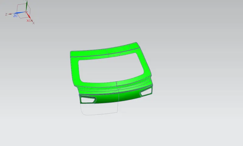
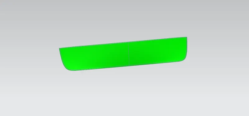
For each upper and lower outer panel I could find positive draft
Back Door inner panel
Inner panel is the part which gives enough strength to the outer panel as well as the it is the part where the viper, Latch, hinge and the gas stays are mounted along with the Reinforcements. Modelling of the inner panel is little Riskier while comparing all the other components of the Back door. The first thing I have created is the sealing flange of the Tail gate
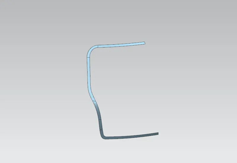
Sealing Flange
Sealing flange is the part of the tail gate where it touches and presses the rubber gasket on the Body side outer in order to avoid the entering of water to the luggage area.
Sealing flange is created by offsetting the outer panel to the required distance and also by creating some studio surfaces guided by some bridge curves.
Embosses For Hinge, viper mount and Gas stays
I have made one emboss for the Hinge in the appropriate position and another one emboss for the Gas stay mount. Also I have made flat surface on the embosses as the hinge and the gas stay need to be mounted on it.
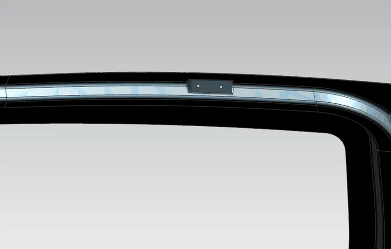
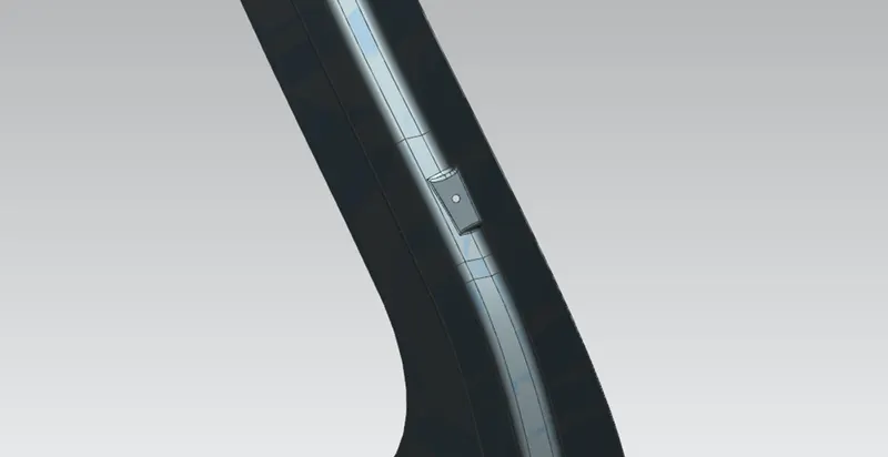
A 5 mm flat space also maintained around the holes for the Fasteners.
Flanges for the mastic
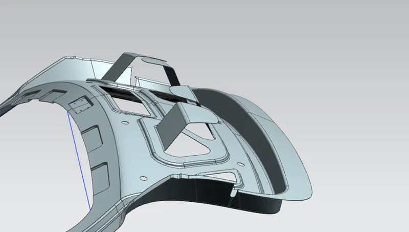
Apart from the hemming the outer panel of the tail gate must be supported using some flanges from the inner panel and some mastic on it. So I have created some cut outs and created some flanges from the edge of the cut outs for creating the mastic points as shown in the figure. The distance from the mastic point to the outer panel is maintained to 5 mm
Embosses for Dissipation of collision force and Cut outs for weight reduction
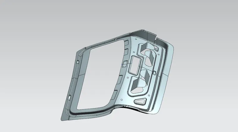
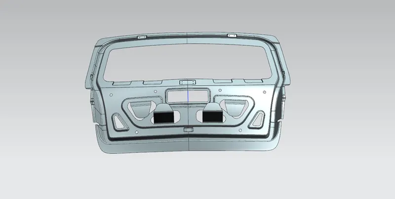
To dissipate collision force getting inside the car, some embosses are made and directed towards the sides of the tailgate as shown in the figure.
From the embossed surfaces some materials are removed in order to reduce the weight of the part.
Latch positioning
Latch positioning is one of the critical operations in the designing of the inner panel. For positioning the latch, first a line is drawn from the axis of one hinge to the axis of the other hinge. After that a trajectory circle is drawn from the centre of the line as it crosses the surface where the latch is placed. And then make the latch axis tangent to the trajectory circle.
Here as i doesn’t have the Hinges as well as the Latch, I am drawing a line from the emboss of the hinge to the other .from that line I have drawn circle and an emboss is created for the Latch where the circle crosses the inner panel.
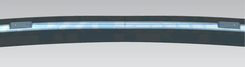
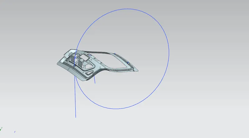
Inner panel final model
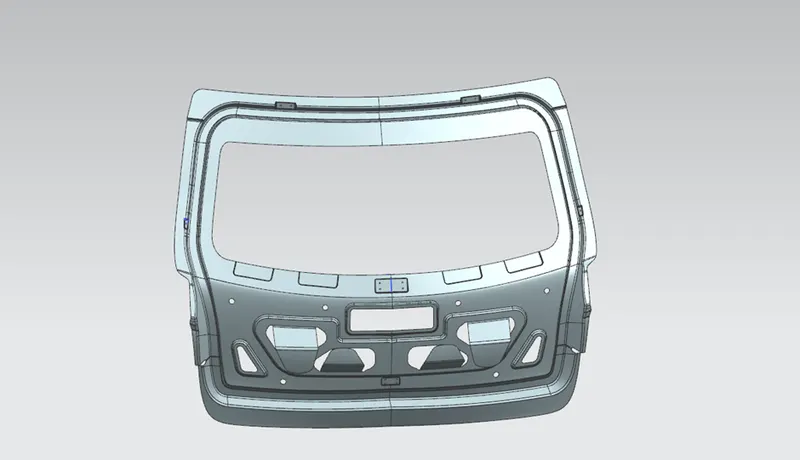
Draft analysis
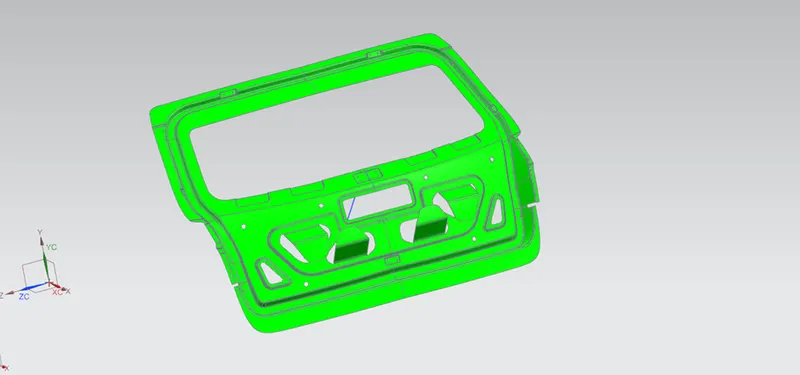
I have created a line for the tooling direction and after draft analysis I could find some embosses with negative draft. But in this case it’s negligible as all the embosses cannot be deep drawn in a single stretch.
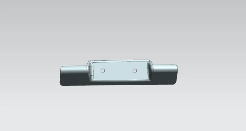
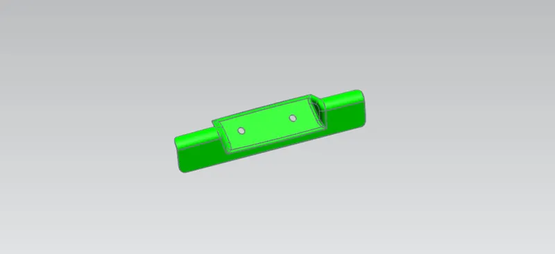
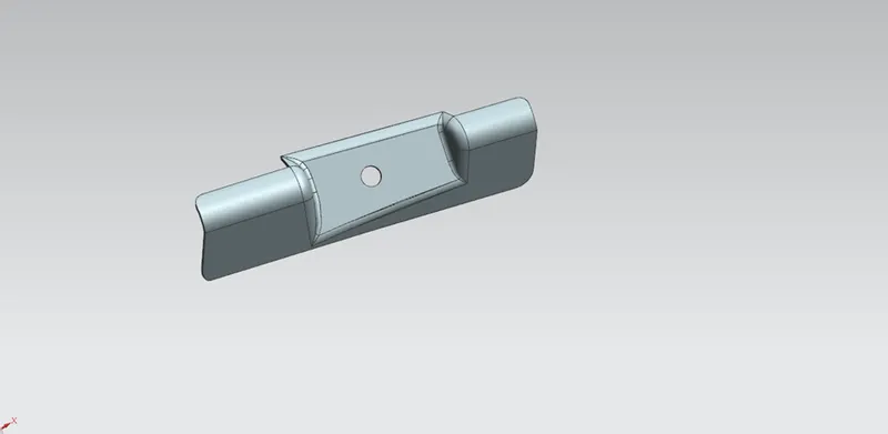
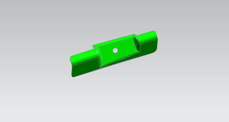
.Reinforcements for Hinge, Gas stay and Viper mount
Reinforcements are used in the areas of a sheet metal where other components are attached. The reinforcements compensate reduced strength of the sheet metal while another component added on it.
Reinforcements are the easier part to create among all other parts in the Tail gate. These are made by using the command wave geometry linker. The proper surface from the inner panel is extracted and trims it to desire shape and then thicken it to get the Reinforcements.
Hinge Reinforcement
Gas stay Reinforcement
Viper mount Reinforcement
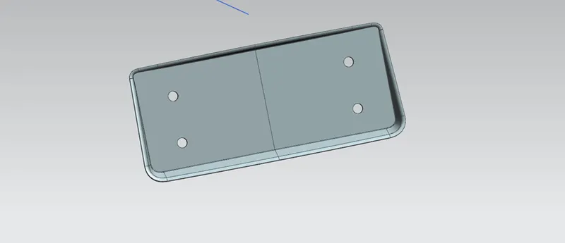
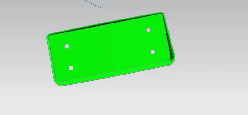
Striker Reinforcement
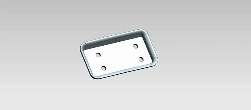
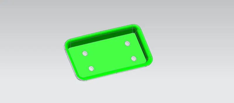
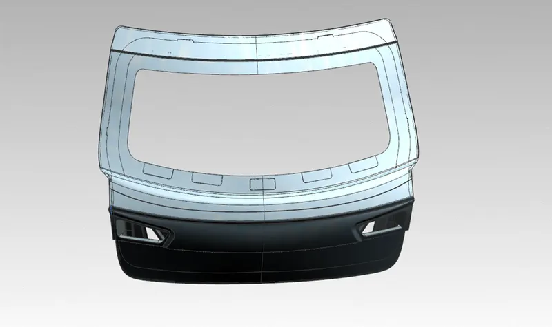
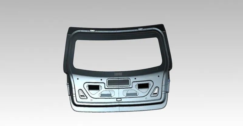
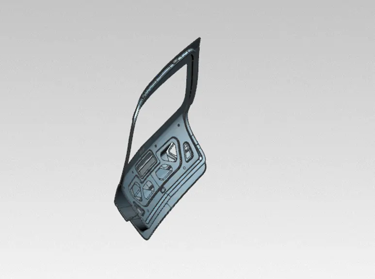
FINAL DESIGN OF THE TAIL GATE
CONCLUSION
Tail gate/back door is being created successfully by following all the design considerations and engineering considerations.