Design of backdoor
DRIVE LINK -(https://drive.google.com/file/d/1S_zLpI4Uz-K9IXDV6eQY0Cp8ZRBxSd89/view?usp=sharing)
DESIGN OF TAIL GATE:
--> Designing of the tailgate has many elements in it
--> Tail gate is divided into 3 major individual parts
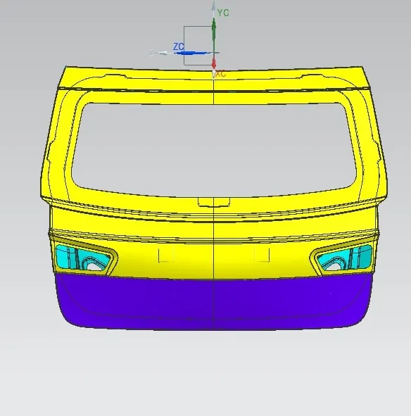
--> Outer panel
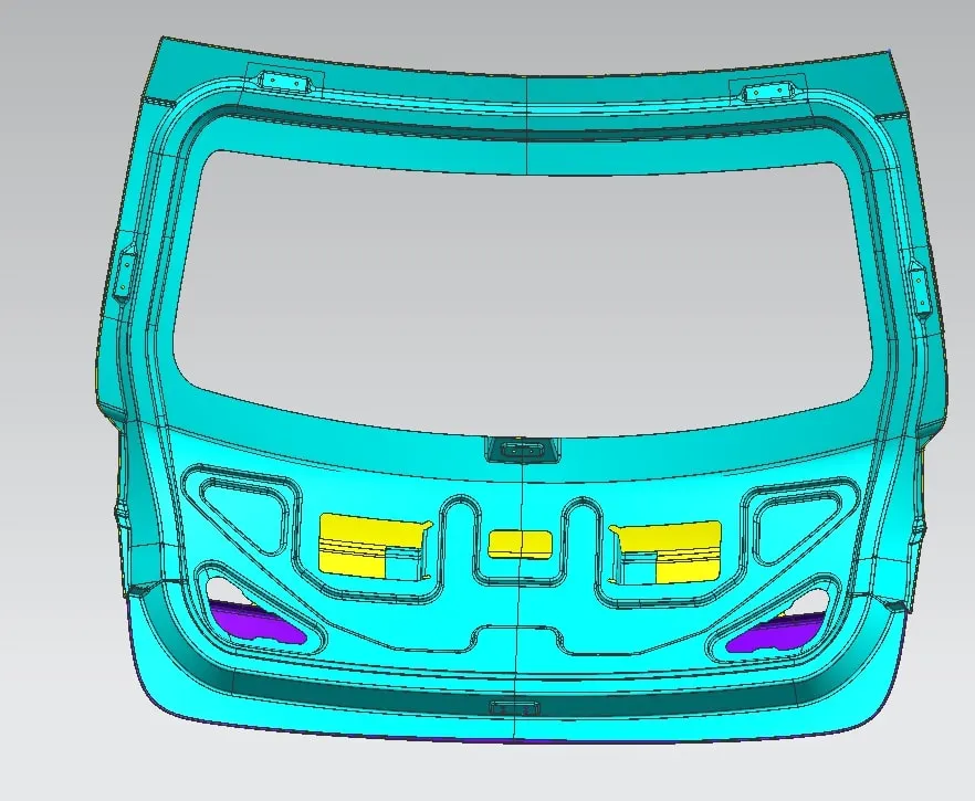
--> Inner panel
--> Reinforcements
--> Outer panel & Reinforcements are further divided so that parts would be separate
--> Outer panel- Lower and upper, Reinforcements – lefts and right
--> First what we have is the skin data of panels outer & inner
--->> THE CRUCIAL POINT IS WE USE TOP DOEN APPROACH IN THIS DESIGNING
--> First we create an assembly from there we create all neccessary parts in the assembly.
--> Now we design all the parts there so we don't have any hiccups later
--> From that skin we link(wave geometry linker) offset it with 0. it to all the necessary parts using so that we have base ready for all of them , as this is only reference we have.
--> Coming step by step now all we have is the offset surfaces to edit with as the original skin data will be left untouched.
--> As always, we create the tooling axis first so that it will used as reference for all the law extensions done
--> Starting with outer panel as we already divide it into two parts we design upper and lower parts separately
OUTER PANEL:
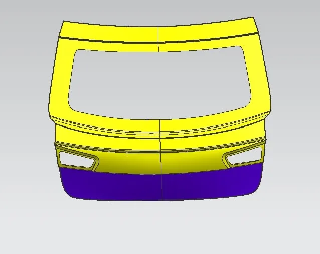
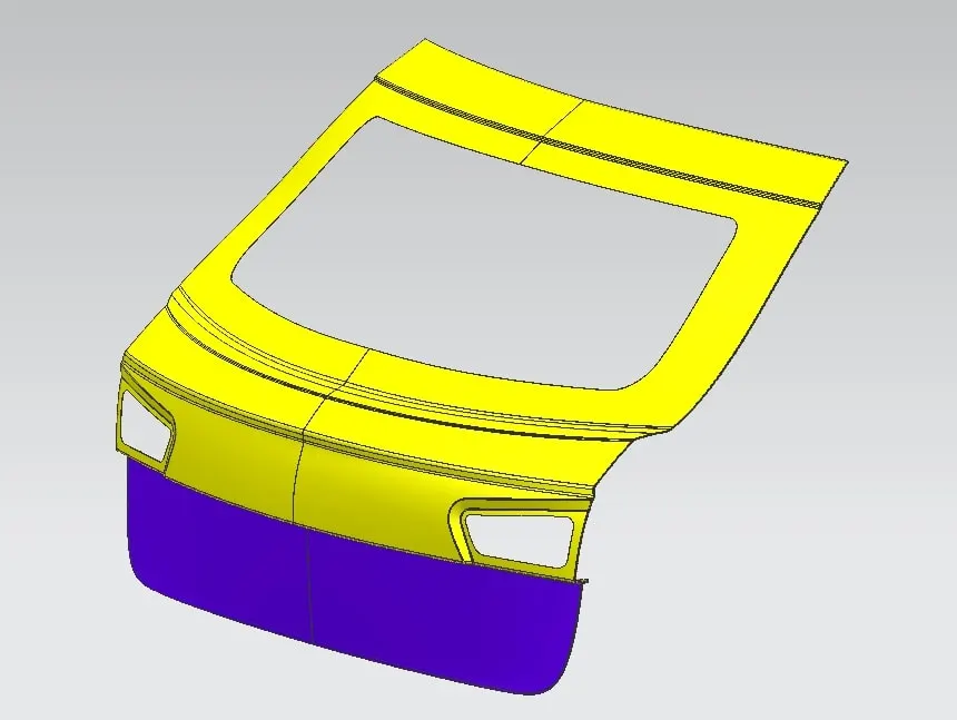
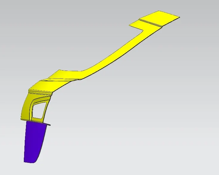
--> The inner panel is the most complicated part in the whole design as it has lot of things to do.
--> We start by creating a flange and then going on with others.
--> As inner panel used to fix the parts, we have all the mounting points here, that are done in inner panel are mountings for Hinges, Gas stays, Wiper motor and latch mounting
INNER PANEL:
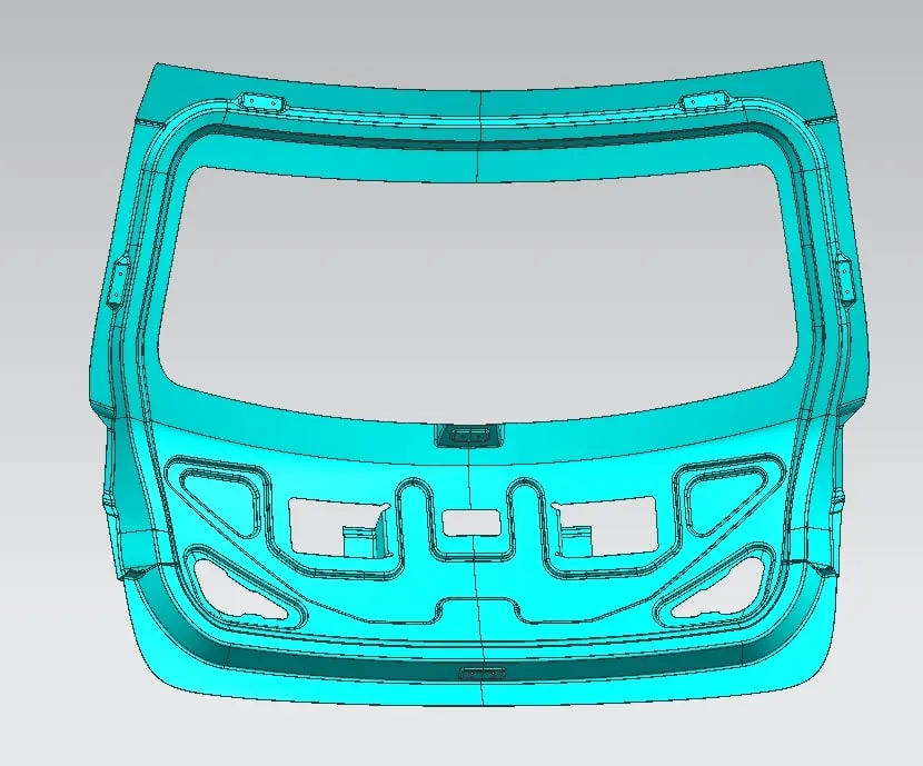
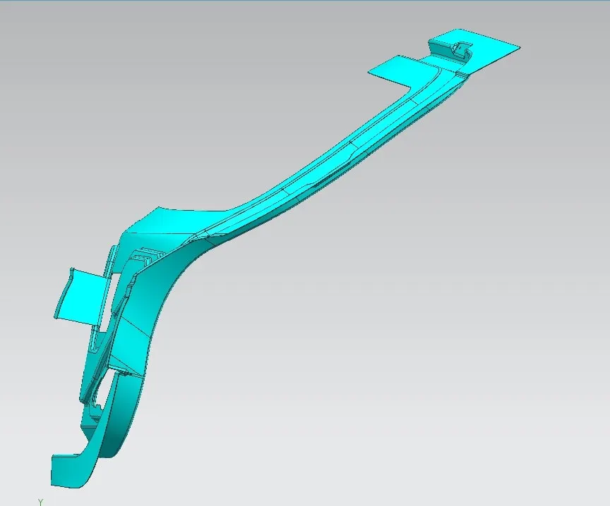
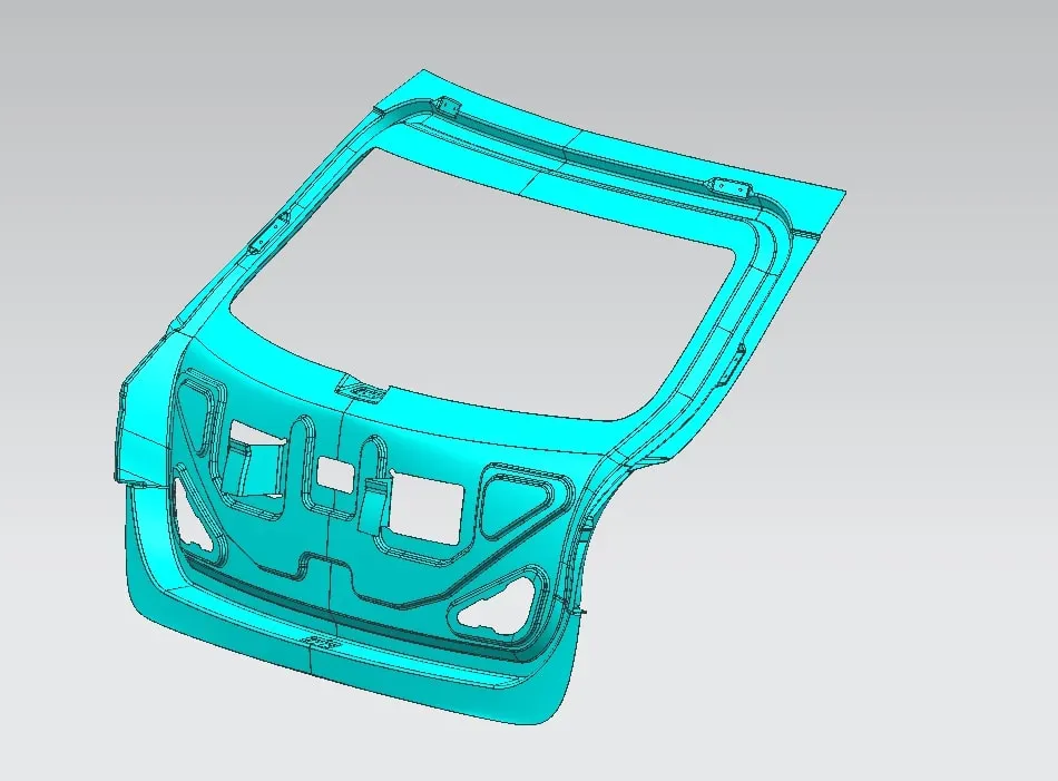
Hinge mounting point:
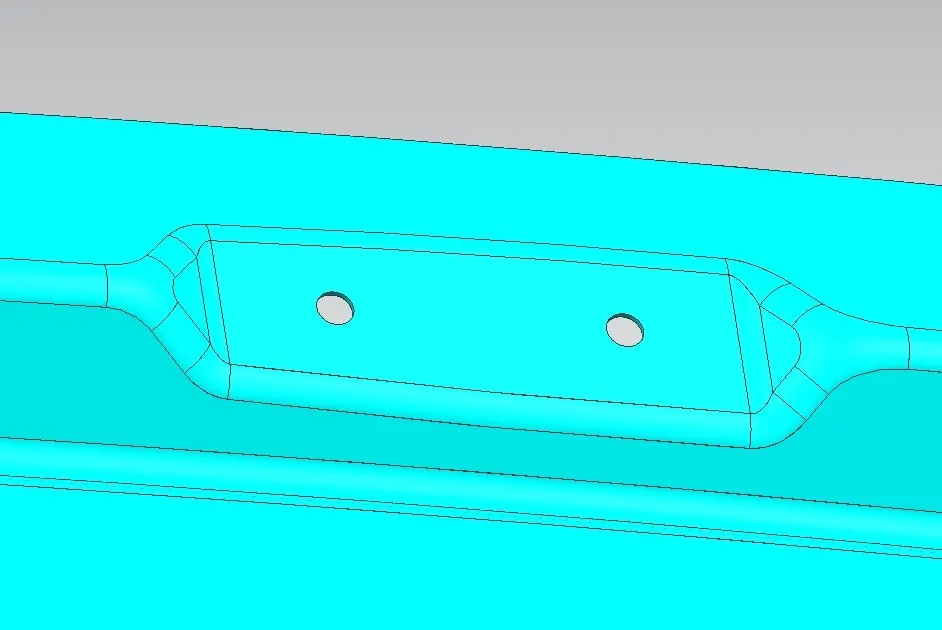
Gas stay mounting point:
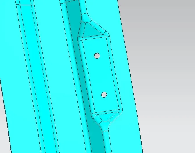
Wiper motor mounting point:
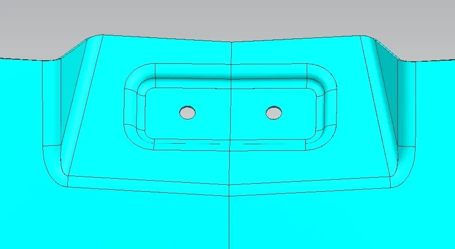
Latch mounting point:
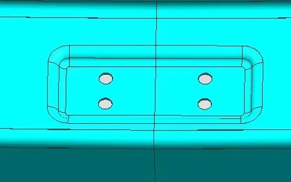
And then we create hole to mount the taillights, in the outer panel from inner panel,
FOR TAIL LIGHT AND HARNESS TO ENTER:
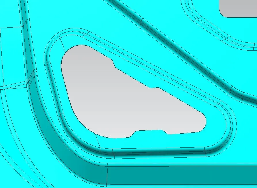
Last one would be creating emboss on the panel so as to absorb the impact when in a collision
EMBOSS:
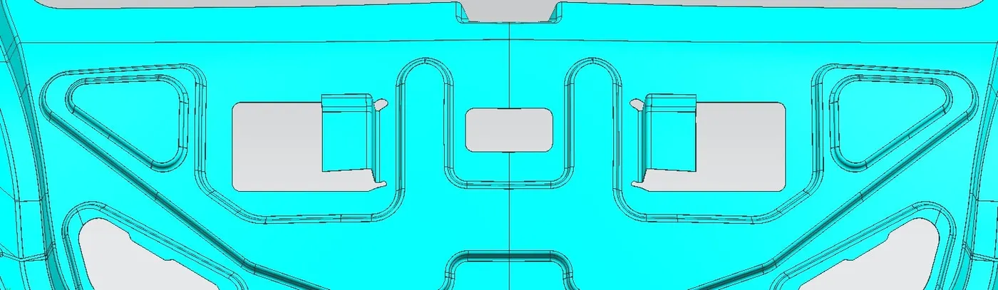
Here comes outer panel which is taken in to create the hemming
HEMMING:
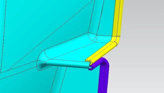
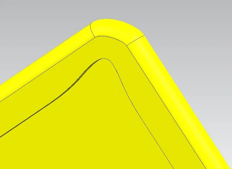
Hem relief:
At last we create the reinforcements for both gas stay and hinge mounting points,
REINFORCEMENTS:
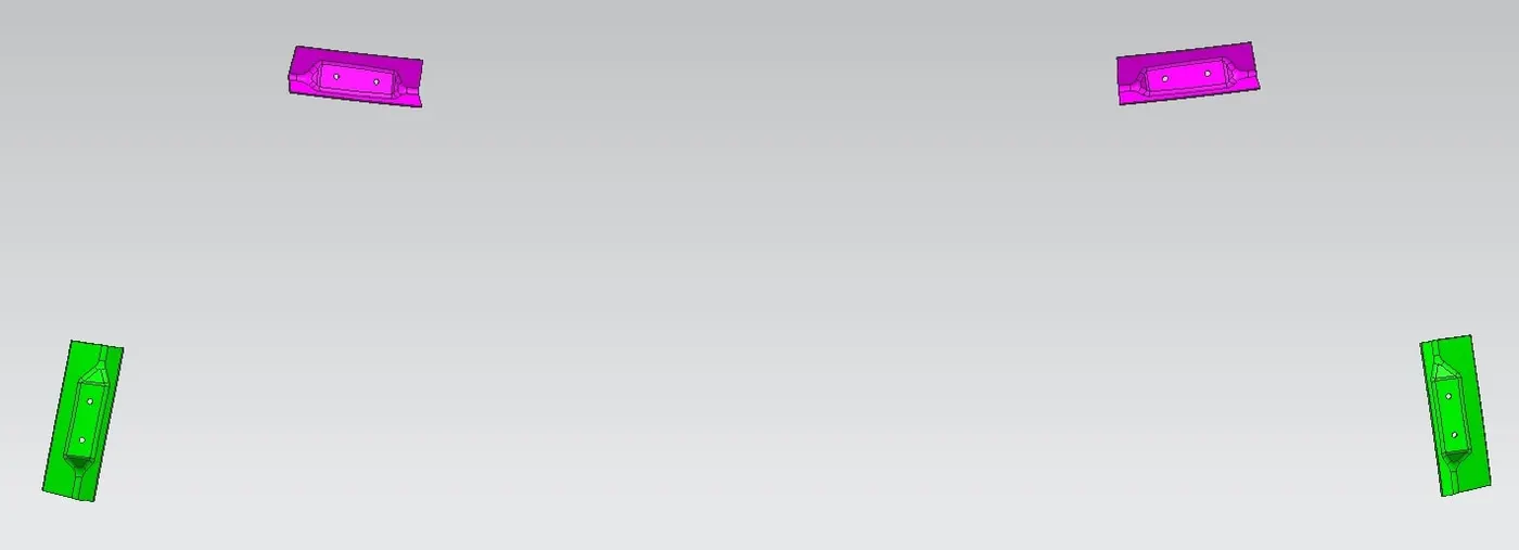
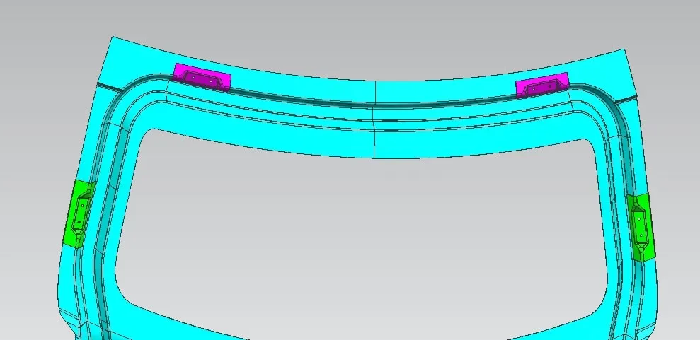
There should be a gap 0f 0.2 mm between the panela and the thickness of the panels is 0.75mm whereas the thickness of the reinforcements is 1.5mm by thickening it the design is done.
Finally the assembly is here
My file is 39mb after compressing it so not able to upload file directly as it only supports max file size 20mb, attached drive link in attach link section and also provided the link in answer box.
step file is attached directly