Design of backdoor
AUTOMOTIVE DESIGN OF CAR BACK DOOR USING NX CAD
OBJECTIVE:
- From the given styling surface, develop a back door using appropriate design methodologies.
- The objective of this project is to design a BIW Back Door of a car with an Inner Panel, Outer Panel, and Reinforcements for the Hinges, Gas stay, Wiper Motor, and Latch by following the engineering standards.
- The Inner Panel must be subjected to Draft Analysis for verifying whether it satisfies the Deep Drawing requirements for the tooling direction created in the design.
SOFTWARE USED:
Siemens NX CAD (Unigraphics)
Introduction
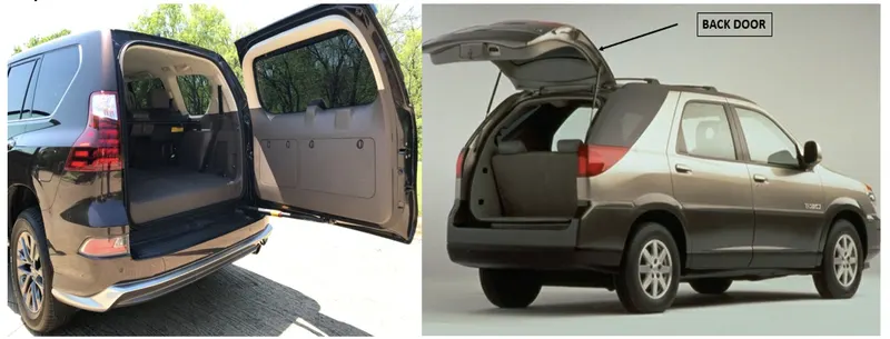
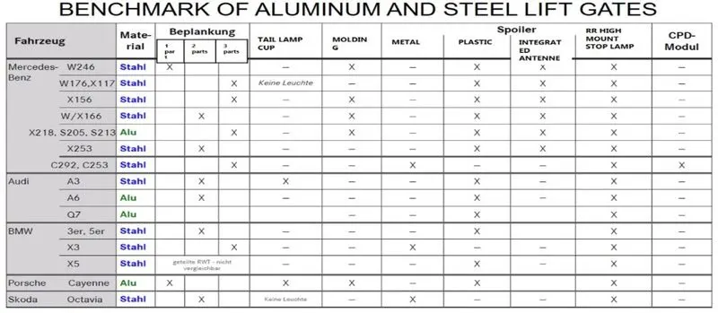
The back door of the car is also known as Tailgate. This is a critical part of back impacts that occur in accidents, which should ensure that crashes wouldn’t injure the passengers. The back door consists of one inner panel and two outer panels. Most of the time the back doors are made from steel or aluminium or plastic based on the budget and the weight of the car the material is selected. In the case of the aluminium, the strength of the back door would be stronger, therefore, reinforcement is not required indeed which will reduce the overall weight of the part. But aluminium is a bit more expensive than steel.
DESIGN CONSIDERATION FOR BACKDOOR INNER PANEL:
- Rear Visibility.
- Support structures like hinges and gas stays
- Mounts for wiper motor, tail lamps, and other wiring loops.
- Fit and clearances.
- Boot space
6.Rear crash regulations and requirements.
7.Sealing and its functions.
8.Joining techniques like hemming, spot welding etc.
TYPES OF DOOR OPENING:
- Top-mounted door
- Side-mounted door
- Bottom Door
In these project, I designed Top-mounted door,So here we discuss mainly about top-mounted door only.
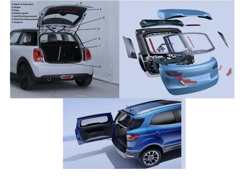
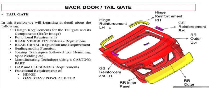
COMPONENTS OF BACKDOOR:
- Inner panel
- Outter panel upper
- Outter panel lower
- Hinge reinforcement LH
- Hinge reinforcement RH
- Gas stay reinforcement LH
- Gas stay reinforcement RH
- Wiper motor reinforcement
- Latch reinforcement
Spot welding
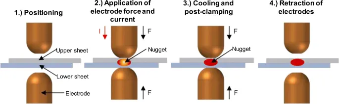
Spot Welding is a form of resistance welding also known as Resistance Spot Welding (RSW). Spot Welding involves using heat produced by resistance to an electrical current to join materials together. The current heats the materials to a point where they become malleable. The use of strong pressure bonds them together.
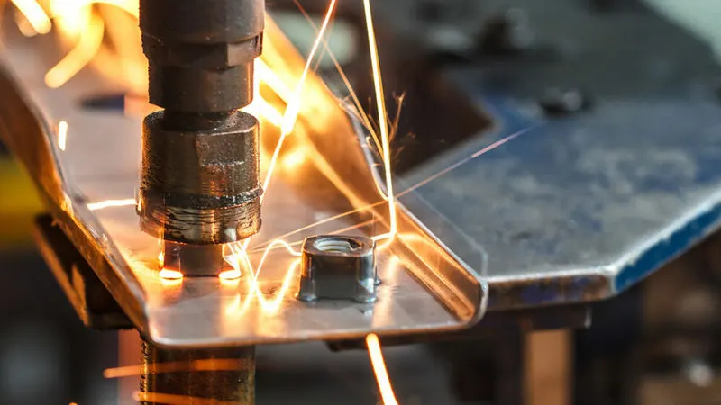
Another form of resistance welding is Projection Welding. This process involves fusing a fastener’s embossed or coined projections to the metal base material to form a weld. As the materials never melt, they do not intermix. This means the resulting weld is more like a forging of the materials. Spot welding is only suitable for a small selection of base materials. Low carbon steel is the most suitable material for spot welding. This is because it is more resistant to electricity and has a lower thermal conductivity than the copper electrodes used to create the required electrical current. High carbon steels and aluminium alloys can form brittle welds that don’t last with the spot welding process. Pure aluminium can qualify for spot welding but requires higher current levels.
Hemming is a forming operation in which the edges of the sheet are folded or folded over another part in order to achieve a tight fit. Normally hemming operations are used to connect parts together, to improve the appearance of a part and to reinforce part edges.
In car part production, hemming is used in assembly as a secondary operation after deep drawing, trimming and flanging operations to join two sheet metal parts (outer and inner) together. Typical parts for this type of assembly are hoods, doors, trunk lids and fenders.
The accuracy of the hemming operation is very important since it affects the appearance of the surface and surface quality. Material deformations, which occur during the hemming process, can lead to dimensional variations and other defects in parts. Typical hemming defects are splits or wrinkles in the flange, material overlaps in the corner areas or material roll-in. This is why it is important to use simulation tools in order to, on the one hand, better understand the hemming process and, on the other hand, significantly reduce the number of “trial and error” loops during tryout und production.
There are various types of hemming operations:
Conventional die hemming
Roll hemming
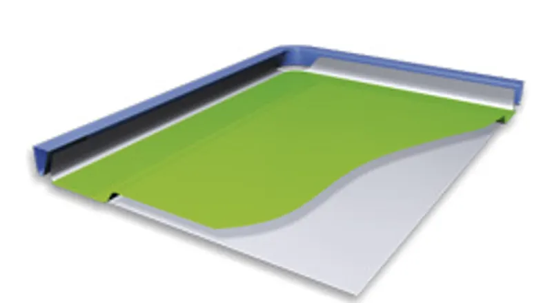
In conventional die hemming, the flange is folded over the entire length with a hemming tool.
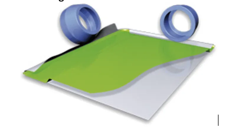
In roll hemming, the hemming roller is guided by an industrial robot to form the flange.
Conventional die hemming
Conventional die hemming is suitable for mass production. In die hemming, the flange is folded over the entire length with a hemming tool. Normally the actual hemming is a result of a forming operation in which the flange is formed with a hemming tool after the drawing and trimming operations have been completed. The formed flange is then hemmed in several process steps. These steps include, for example, the pre-hemming and final hemming depending on the respective opening angle of the flange. Production plants for conventional die hemming are very expensive, but the cycle times are very low.
Roll hemming
Roll hemming is carried out incrementally with a hemming roller. An industrial robot guides the hemming roller and forms the flange. Roll hemming operation can also be divided into several pre-hemming and final hemming process steps. Roll hemming is very flexible to use and tool costs are significantly lower as compared to those of conventional die hemming. However, the cycle times are much higher since the hemming is realized using a hemming roller which follows a defined path.
Sheet Metal Punching Process
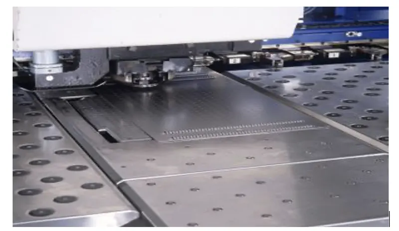
Sheet metal punching is a cutting process in which material is removed from a piece of sheet metal by applying a great enough shearing force.
CNC Punching can be used to produce holes and cutouts of various shapes and sizes.
The most common punched holes are simple geometric shapes (circle, square, rectangle, etc.) or combinations thereof.
The die, located underneath the sheet, has a cutout in the shape of the desired feature.
Punches and dies of standard shapes are typically used, but custom tooling can be made for punching complex shapes.
The punch press drives the punch downward at high speed through the sheet and into the die below.
There is a small clearance between the edge of the punch and the die, causing the material to quickly bend and fracture.
The slug that is punched out of the sheet falls freely through the tapered opening in the die.
This process can be performed on a manual punch press, but today computer numerical controlled punch presses are most common.
A CNC punch press can be hydraulically, pneumatically, or electrically powered and deliver around 600 punches per minute.
Sheet Metal Embossing
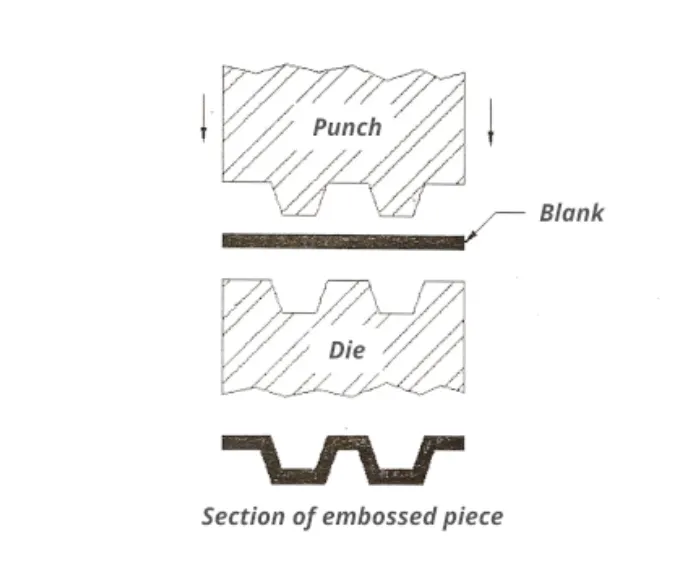
Sheet metal embossing is a metal forming operation in which the sheet metal is stretched into a shallow depression.
Sheet metal embossing is generally used to create logos, lettering, small depressions, etc. It is also used to create desired non-slip surfaces as well as other geometric features on the sheet metal.
In sheet metal embossing, the deformation of the metal takes place because of stretching of the metal (or tensile force acting on the metal), due to which the sheet metal is subjected to excessive thinning and fracturing.
Thus the depth to which the material is depressed depends upon the thickness of the sheet as well as stretchability of the material.
Embossing is generally used to make dimples on sheet metal to increase their rigidity as well as it is also used for decorative purposes on panels in houses or other places.
3 things to control during the embossing of sheet metal
- Pressure:Pressure applied to the sheet metal should be controlled during embossing.
- Heat:Heat level should be maintained consistently during the embossing to get the perfect impressions.
- Die depth:The depth of the die should be adjusted such that the extreme thinning or failure of sheet metal does not occur.
These three factors mostly determine the quality of the embossed product.
During the embossing of sheet metal, the metal sheet is drawn through the male and female roller dies, which ultimately produces a pattern or design on it.
Various types and shapes of dies are used to obtain the desired embossment on the metal sheet.
The combination of pressure and heat is like the principle of ironing the cloth, but here the sheet is depressed instead of straightening.
Design of Back door in NX CAD:
Door parts thickness is given below,
- Outer Panel - 0.75 mm
- Inner Panel - 0.75 mm
- Reinforcements - 1 mm
Given Data
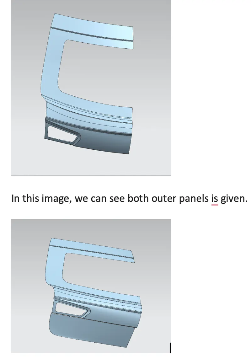
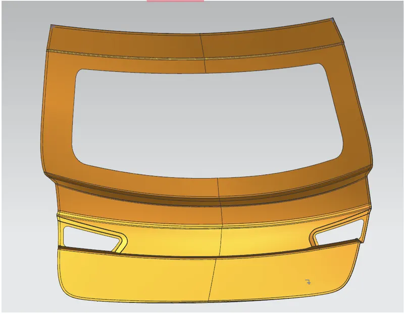
Hemming is done on the both Outer Panel with the Corner Relief
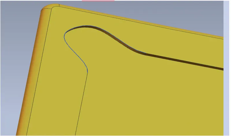
OVERALL OUTER PANAL IS SHOWN BELOW WITH HEMMING
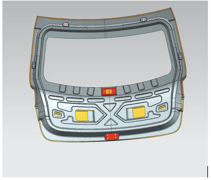
Back door inner pane
The back door is going to be manufactured by a deep drawing process. In Deep Drawing, the process have a tool which is a core and Die. The core part follows a single Straight path the inclination angle of the core is known as a tooling direction. The tooling direction/axis is created so, that the Manufacturing team take the reference of this tooling axis and manufactures the part accordingly.
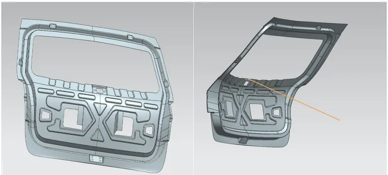
How the inner panel is made is shown in the bellow image
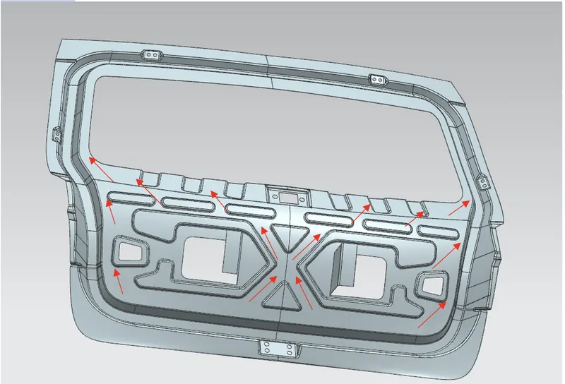
Force Distribution
When the car hits at the rear end, the impact force should dissipate outside for safety. For that we give Y/V emboss which helps to direct the force to the outer end.
MASTIC SEALANT:
The mastic sealant is used to fix the inner panel and the outer panel which increases the NVH factor & stiffness of the back door.
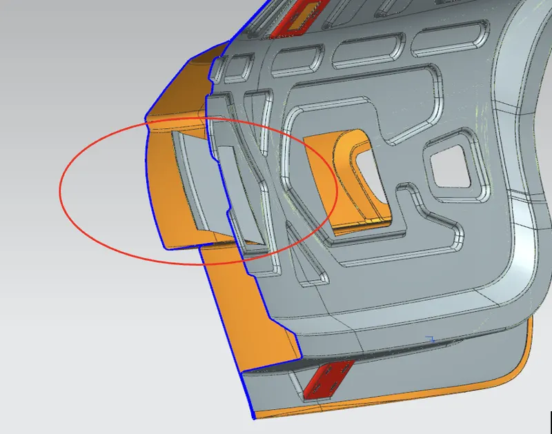
4 to 5 mm Gap for the mastic sealent
Hinge Emboss,wiper motor emboss,gas stay emboss and latch and striker trajectory.
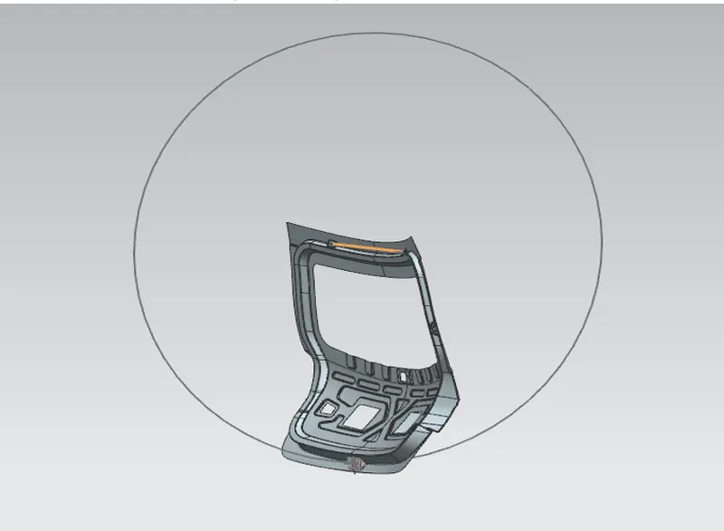
The backdoor is a swinging commodity, which swings with the help of hinges. This can be done by tentatively positioning the hinges and on the hinge axis, we take a center point. again we take another center point(approx) on the latch hole. Taking these two points as a reference we draw a circle. This circle is the striker trajectory and it has to be perpendicular. This can be achieved by moving the hinge axis back and forth or by rotating the latch area.
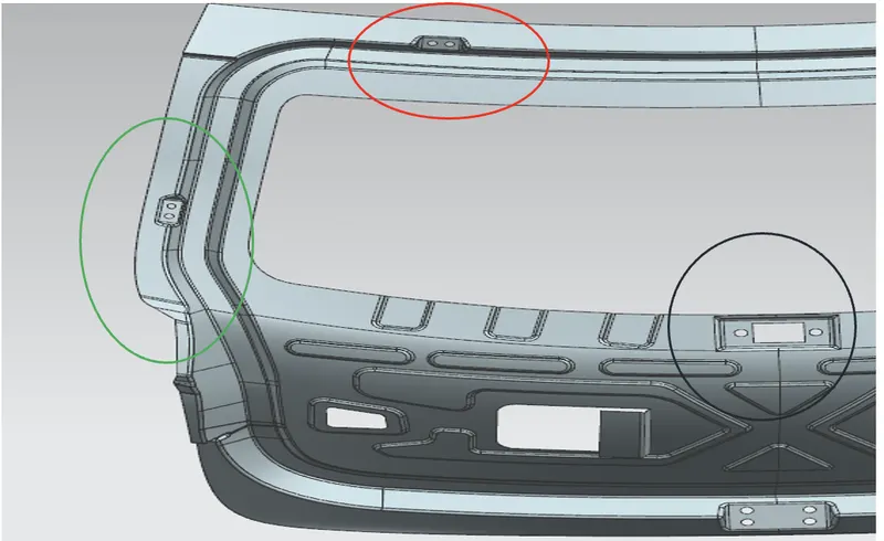
The red circle shows the hinge emboss Green circle show the gas stay emboss and the black circle shows the wiper motor emboss.
Latch and striker trajectory For the Latch Position a circle was drawn from the axis of hinges to find out the trajectory
Reinforcements
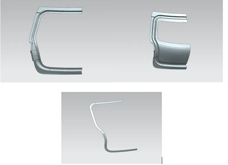
Reinforcements are used to support and provide stiffness and strength to other components of BIW(Body In White).
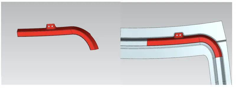
Hinge Reinforcement-
The hinge reinforcement is provided in order to give strength to the inner panel. This is one of the parts which carries the load and requires strength.
Hinge left
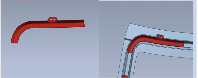
Hinge right
Gas stay reinforcement
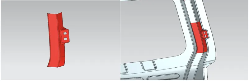
A gas-stay reinforcement is a required because the gas stay will carry the load of the backdoor in open position.
Gas stay left
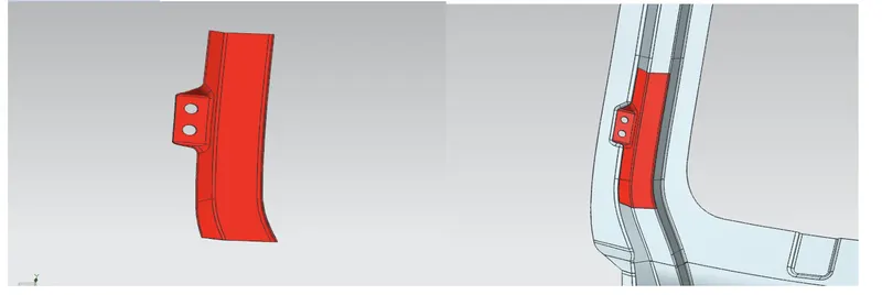
Gas stay right
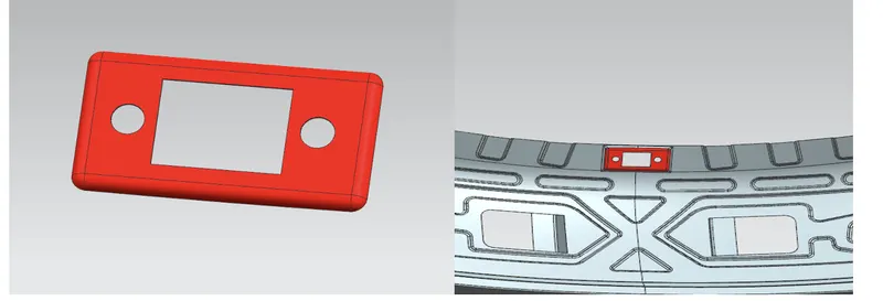
The Wiper-Motor Reinforcement
The Wiper-Motor Reinforcement is provided for incresing the strength of the wiper motor location
The latch reinforcement
The latch reinforcement is required because the latch will fall over the striker with a good amount of force, so here the strength is mostly required to bear the force.
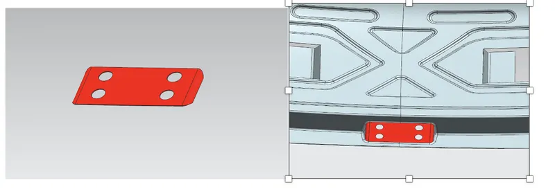
Draft analysis
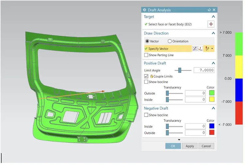
Draft analysis of the inner panel is carried out through the tooling direction only. Only the green areas are acceptable and in worst cases yellow regions are accepted but the blue and red regions are never accepted.
In this project I considered it as steel and used 7 degrees as the draft angle and direction is chosen as tooling direction which is the deep-drawn direction.
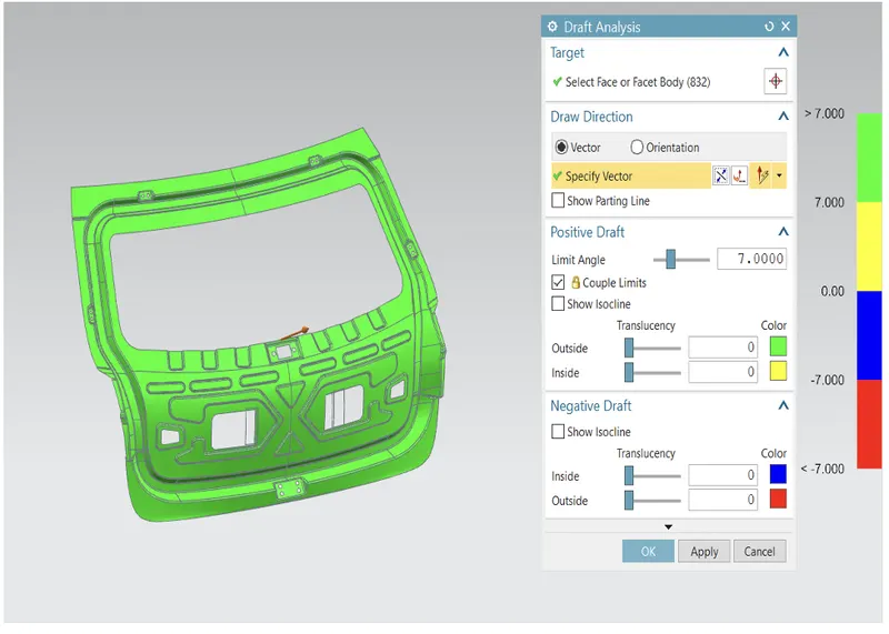
In this daft analysis specify vector is selected as tooling direction
The clip section image is shown bellow
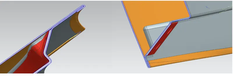
In this image, we can clearly see how the inner panel and outer panel are joined to gather.
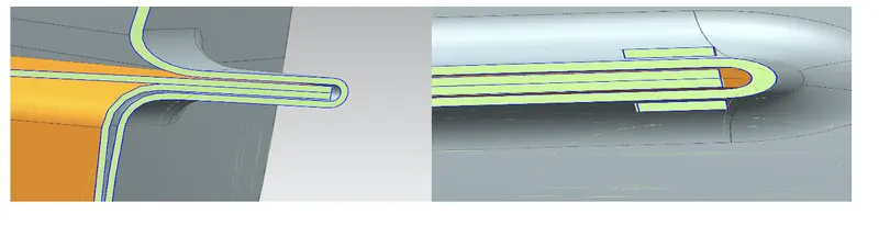
0.2 mm gape is given in between the inner and outer panel for mastic selenate.
Reinforcement image are shown bellow
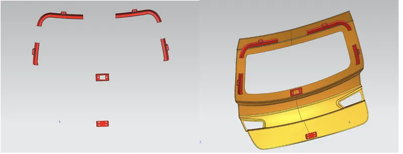
Different view of backdoor assembly
Front view
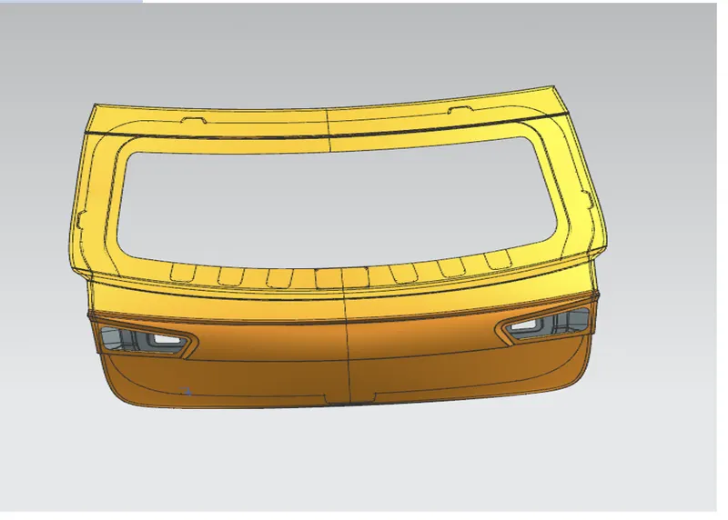
Isometric view
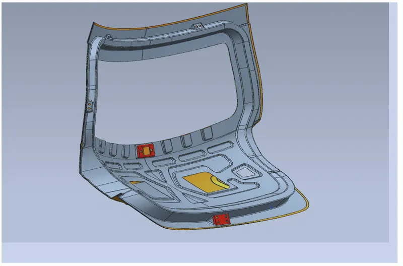
Back view
Conclusion
The back door was designed in software called siemens nx cad 12 the back door is designed with consideration of all design factors.