Design of backdoor
DESIGN OF AN AUTOMOTIVE TAIL GATE
AIM :
To Use the provided styling surface and come up with a back door design, use appropriate design methodologies, and to provide the necessary reinforcements and embosses.
TAILGATE:
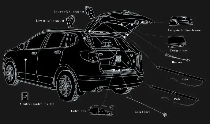
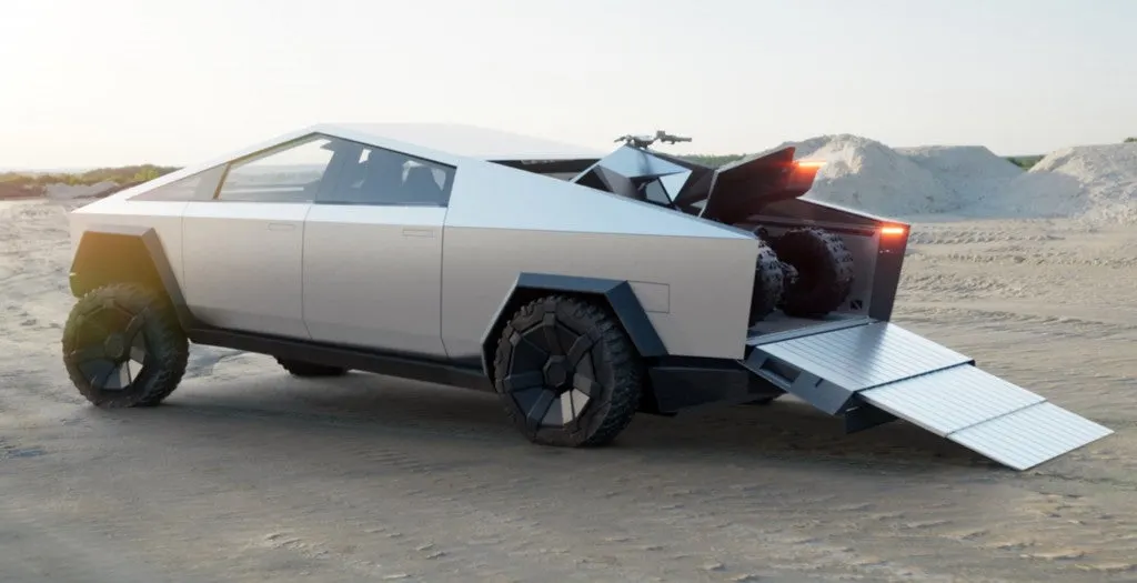
A tailgate is that rearmost part of a pick-up truck or SUV which opens downward and gives access to the cargo area of the vehicle.
A “tailgate” can also be a term for a casual, impromptu party generally involving finger food and adult beverages consumed before or after a sporting event. “Tailgating” generally occurs in the parking lot of said sporting event.

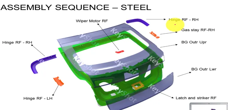
Assembly parts of Tail Gate:
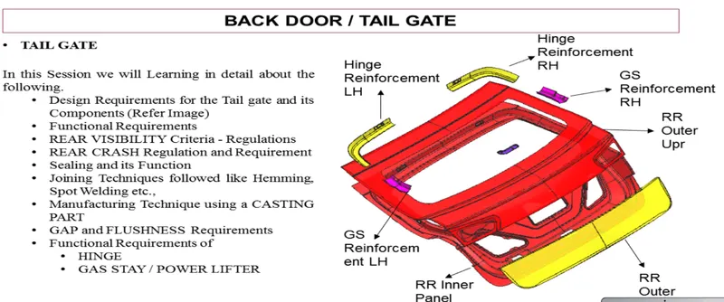
- Back Door Inner Panel
- Outer Panel
- Hinge Reinforcements
- Gas stay Reinforcements
- Latch & Striker Reinforcement
- Wiper Motor Reinforcement
DESIGN OF TAIL GATE:
First the Asthetic or Class A surface is given as input surface for design of tailgate/Backdoor.
The Asthetic surface is given belo.
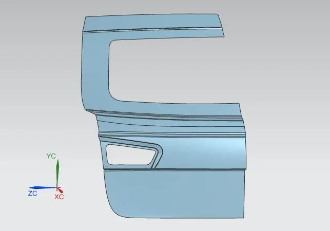
Now the above surface should be designed in such a way that all assembly parts should be accomodated under outer panel with embosses and reinforcements.
Creation of tooling axis:
For every part tooling axis is more important to get cleared draft analysis where part can be easily detached from punch after required shape is achieved.
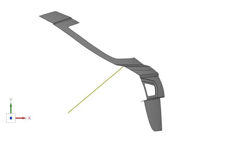
Design of ceiling flange:
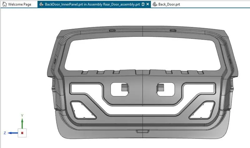
The ceiling flange is created from Top panel Top & Top panel bottom offset and using bridge curves flange is created to sit exactly on to the rear housing using rubber ceiling.
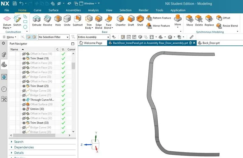
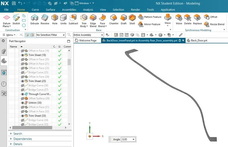
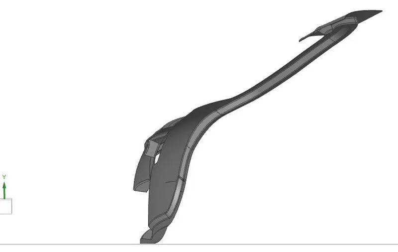
Now the Flange is made law extension with tooling direction towards Upper panel and trimmed with top panel.
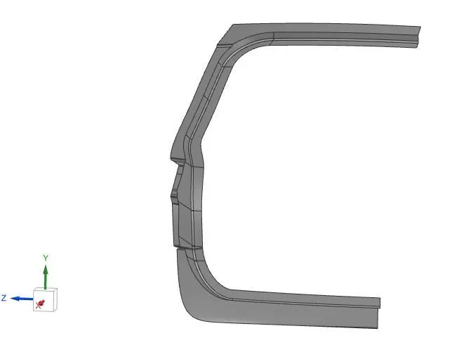
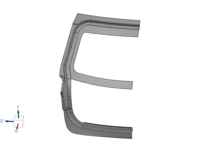
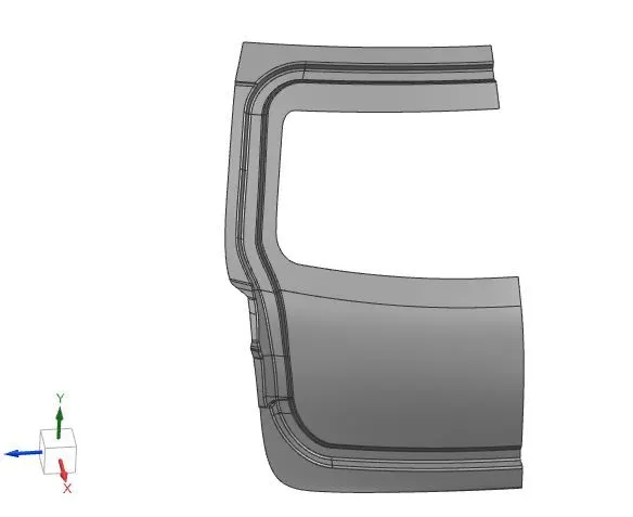
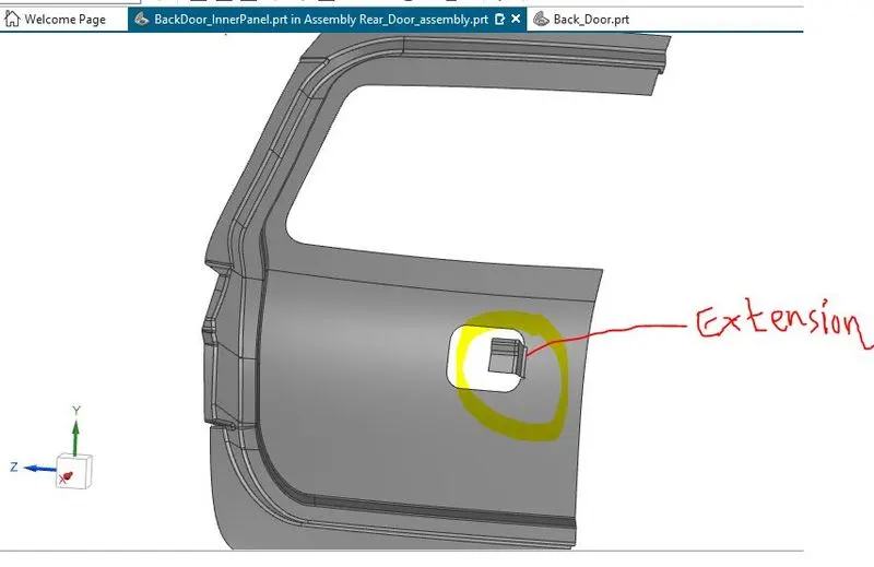
To attach the inner panel to the Upper panel an extension is made towards the upper panel that is attached by mastics and also provides a support member for panel strength.
Embosses for strength and forces diversion :
The embosses for reinforcements Striker latch and Y-Emboss is created for the attachments and strength purposes.
Then the whole geometry is mirrored with centre plane to get full inner panel structure and then both should be sewed.
Latch & Striker Reinforcement:
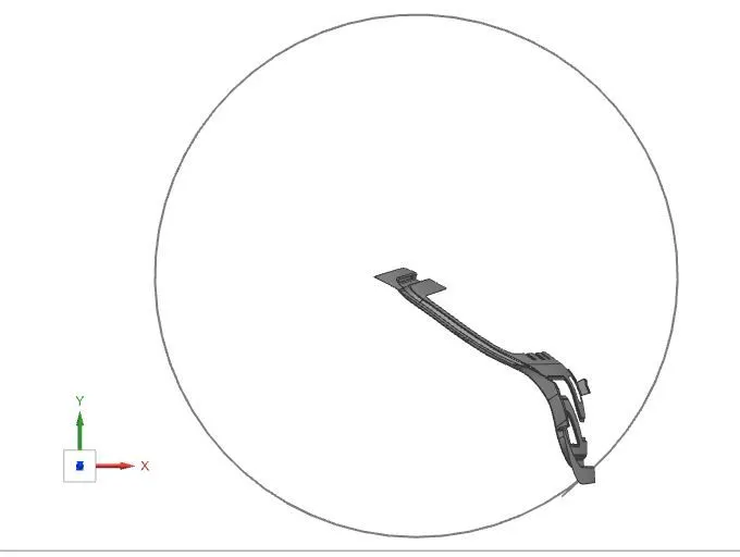
For the creation of latch and striker the hinge axis is taken as reference and a circle is drawn with a radius.
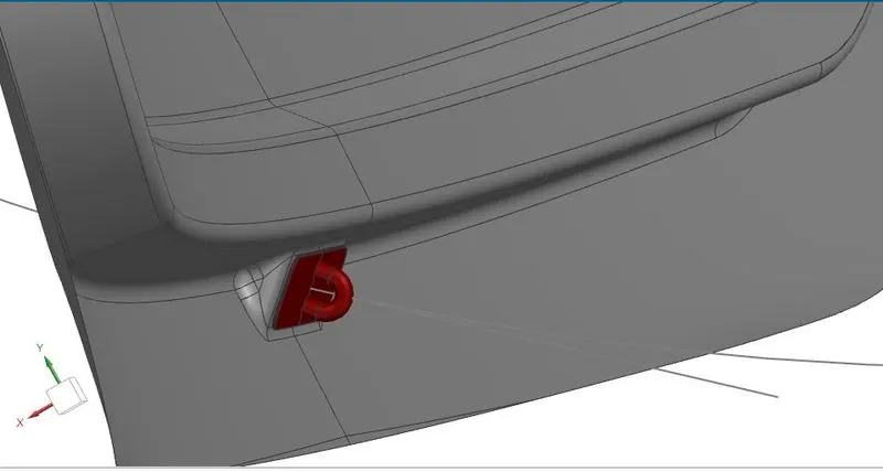
A tangent line is drawn to the circle at the position of striker emboss and striker latch with striker is created.
Then latch can be spot welded to the inner panel.
Hinge & Gas Stay Reinforcements:
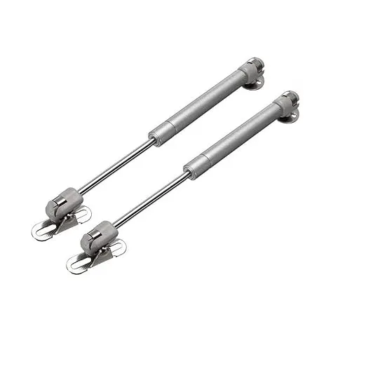
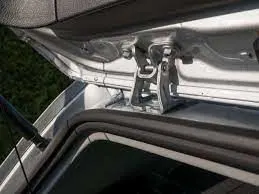
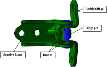
| Gas Stay 1 | Gas Stay 2 | Door Hinge 1 | Door Hinge 2 | Door Hinge 3 |
 |
 |
 |
 |
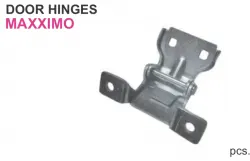 |
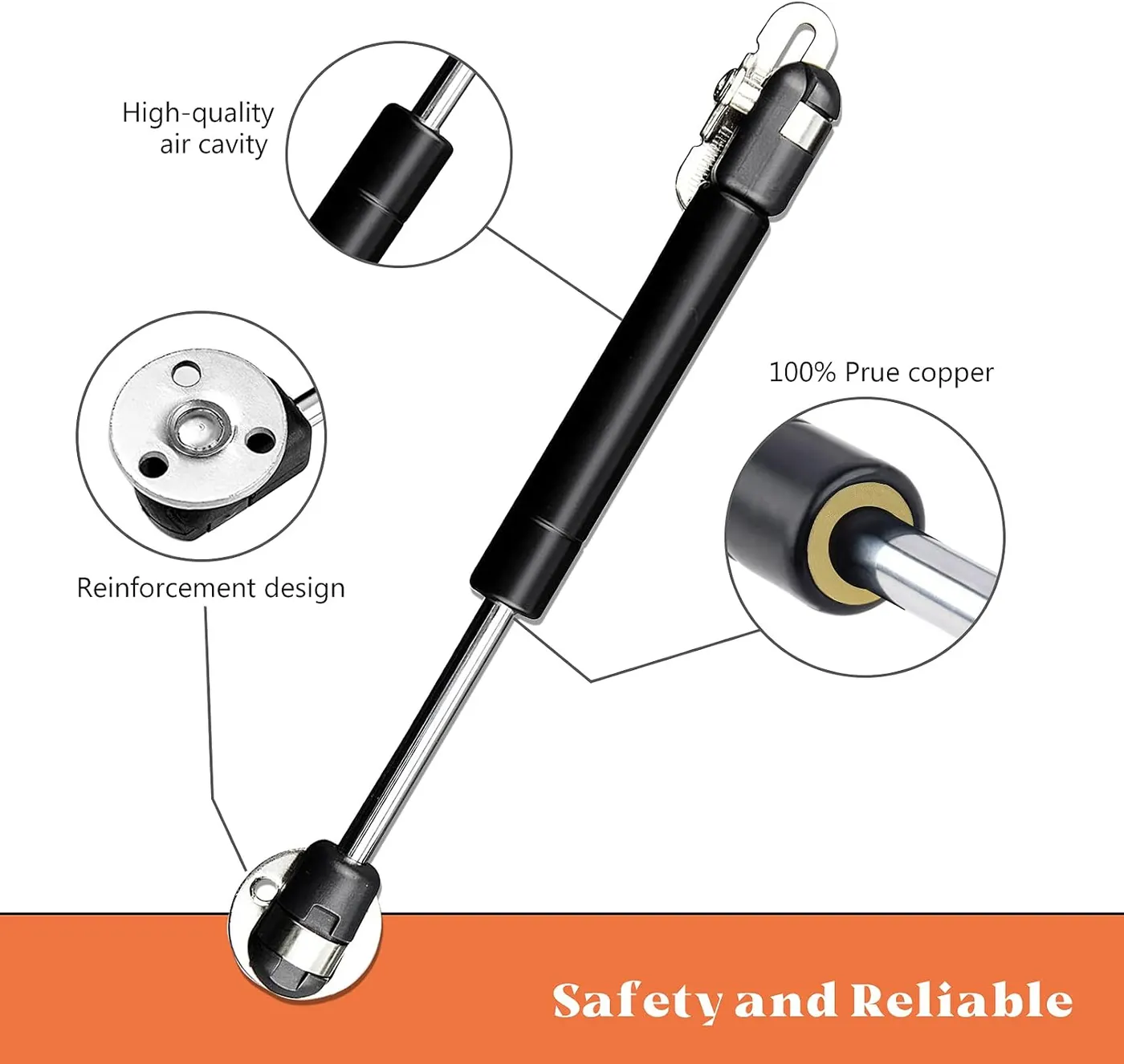
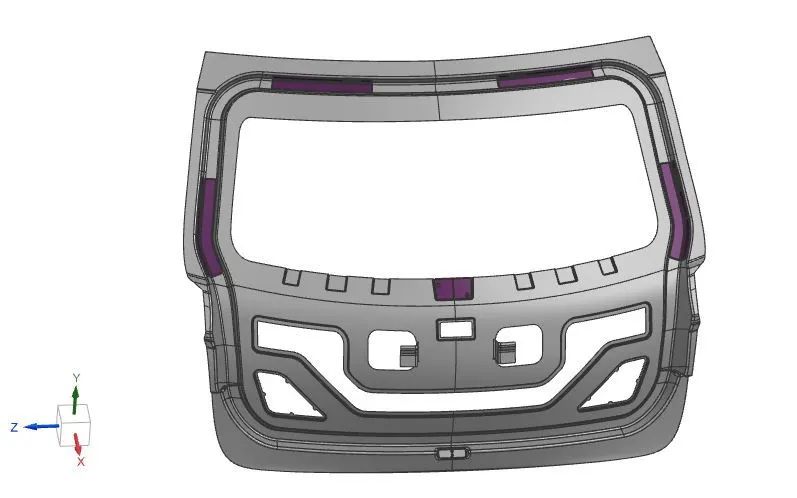
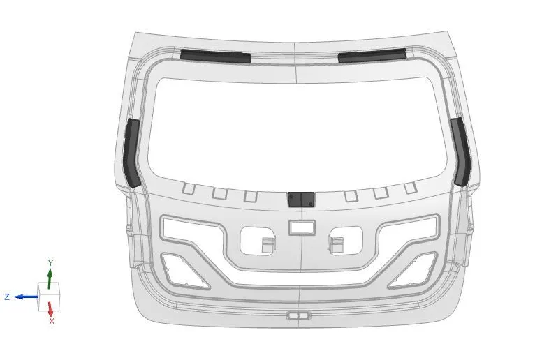
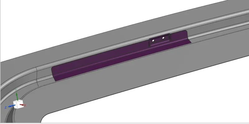
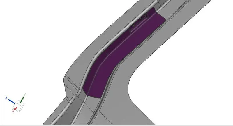
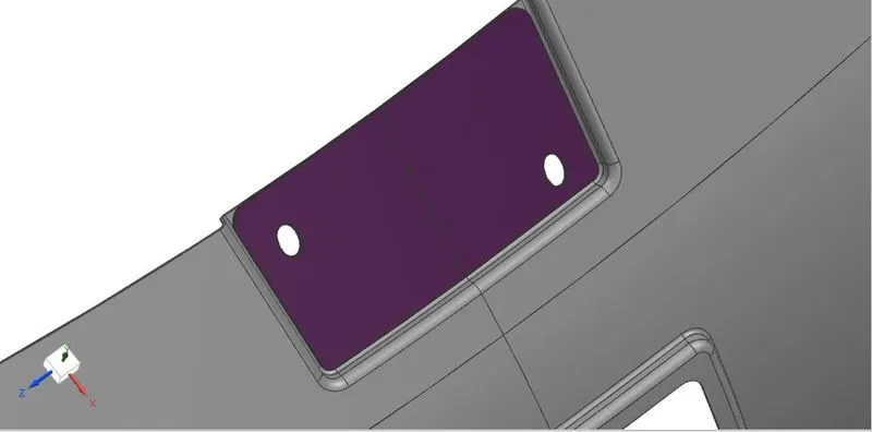
All reinforcements(Left&Right hinges and gas stays) were created for positioning the hinges and gas stays.
All Reinforcements were created which are shown below:
HEMMING:
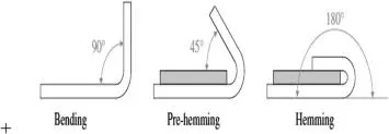
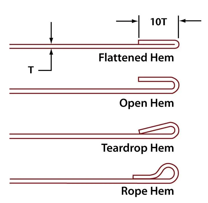
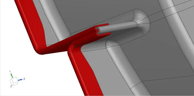
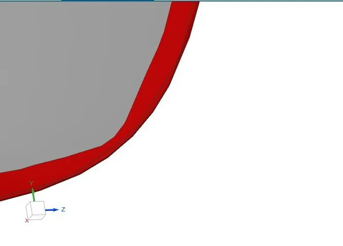
Hemming is a sheet metal forming process in which sheets are joined by bending it to 180°. Automotive body panels and automotive parts such as deck-lids, trunk-lids, doors, hoods and tailgates are formed by hemming process. In this process, usually a sheet is bent with the help of inner sheet in three different stages.
Hemming is a forming operation in which the edges of the sheet are folded or folded over another part in order to achieve a tight fit. Normally hemming operations are used to connect parts together, to improve the appearance of a part and to reinforce part edges.
In car part production, hemming is used in assembly as a secondary operation after deep drawing, trimming and flanging operations to join two sheet metal parts (outer and inner) together. Typical parts for this type of assembly are hoods, doors, trunk lids and fenders.
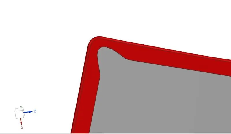
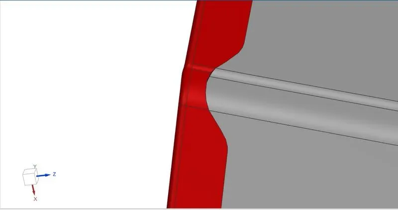
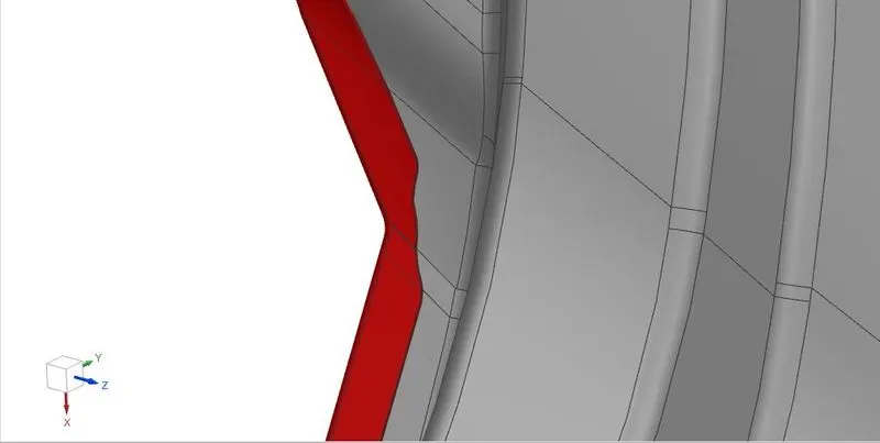
The accuracy of the hemming operation is very important since it affects the appearance of the surface and surface quality. Material deformations, which occur during the hemming process, can lead to dimensional variations and other defects in parts. Typical hemming defects are splits or wrinkles in the flange, material overlaps in the corner areas or material roll-in. This is why it is important to use simulation tools in order to, on the one hand, better understand the hemming process and, on the other hand, significantly reduce the number of “trial and error” loops during tryout und production.
There are various types of hemming operations:
- Conventional die hemming
- Roll hemming
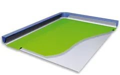
In conventional die hemming, the flange is folded over the entire length with a hemming tool.

In roll hemming, the hemming roller is guided by an industrial robot to form the flange.
Conventional die hemming
Conventional die hemming is suitable for mass production. In die hemming, the flange is folded over the entire length with a hemming tool. Normally the actual hemming is a result of a forming operation in which the flange is formed with a hemming tool after the drawing and trimming operations have been completed. The formed flange is then hemmed in several process steps. These steps include, for example, the pre-hemming and final hemming depending on the respective opening angle of the flange. Production plants for conventional die hemming are very expensive, but the cycle times are very low.
Roll hemming
Roll hemming is carried out incrementally with a hemming roller. An industrial robot guides the hemming roller and forms the flange. Roll hemming operation can also be divided into several pre-hemming and final hemming process steps. Roll hemming is very flexible to use and tool costs are significantly lower as compared to those of conventional die hemming. However, the cycle times are much higher since the hemming is realized using a hemming roller which follows a defined path.
DRAFT ANALYSIS:
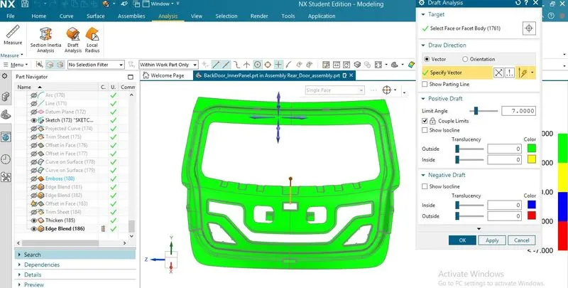
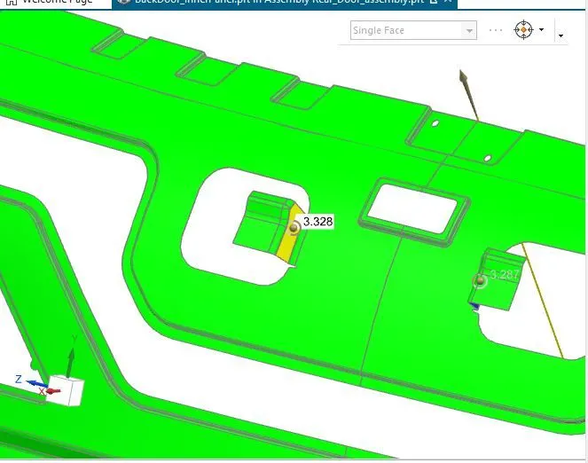
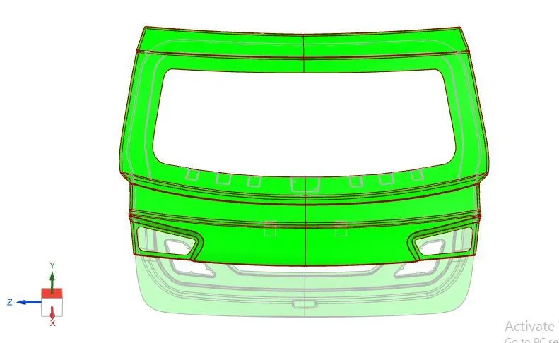
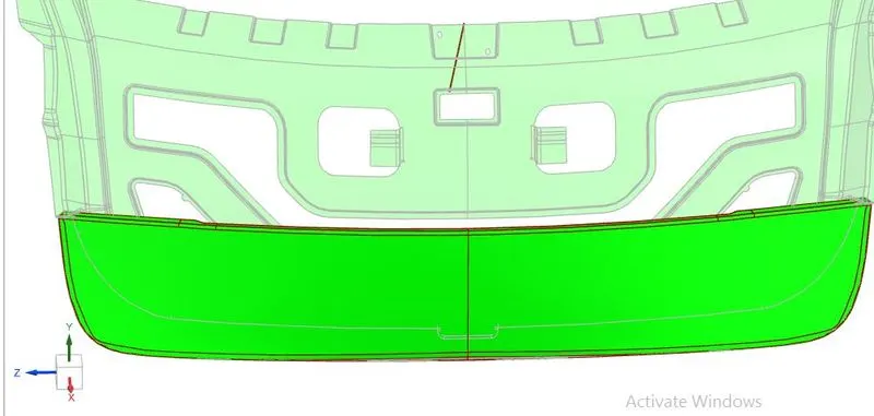
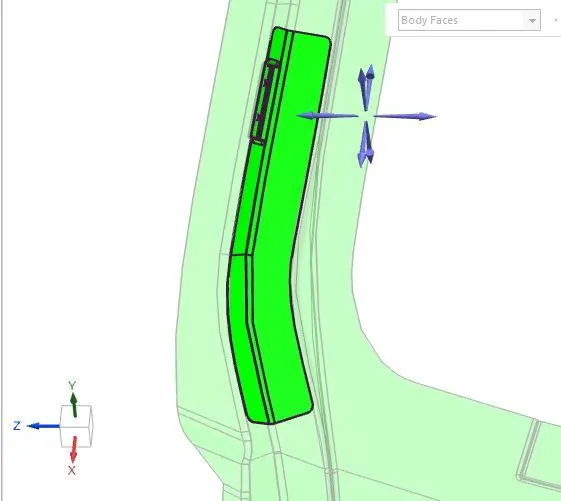
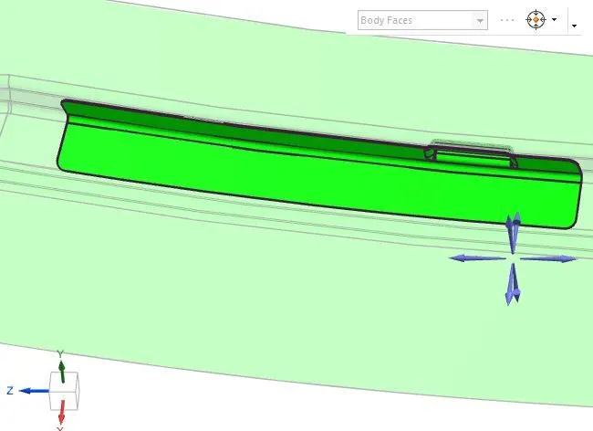
Shaped sheet metal parts (Assembly) should meet the minimum draft angle criteria of angle 7 degree at which the part can be easily punched and removed. So it is important to check the draft angle for every assembly part.
Draft angle check for Inner Panel:
Outer panel:
Reinforcements:
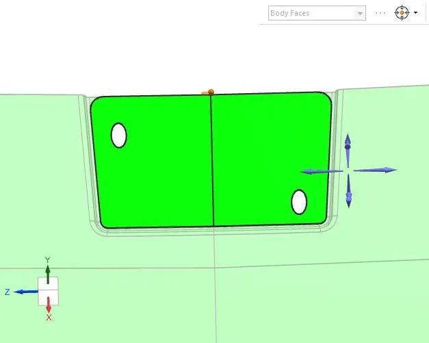
Draft Analysis for Hinge, Gas Stay and Wiper motor Reinforcements.
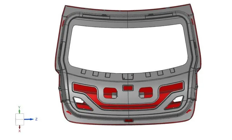
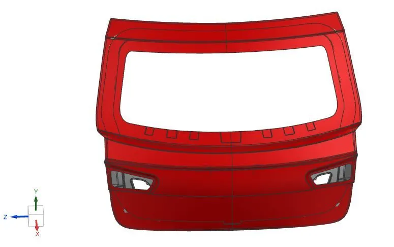
Final Image of assembly:
GOOGLE DRIVE LINK: