Design of backdoor
OBJECTIVE:
To design the back door using the given styling class A surface by using appropriate design methodologies, and provide the necessary reinforcements and embosses.
INTRODUCTION:
The Back Door of a car is the rearmost part of the vehicle which gives access to the trunk space of the vehicle. The rear door also supports the reinforcements and added weights of the Wiper Motor, Gas Stay, Tail Lamp, and Latch and Striker.
The Backdoor/tailgate is one of the closure commodities in BIW sheet metal design. The backdoor has a lot of components inside and is designed to corporate them easily. It affects the rear visibility and luggage area.
In this project, I have designed a back door for a hatchback car where it is hinged at roof level. Similar to the hood and side doors, the backdoor is a swinging/closure commodity in a car. It consists of an outer and inner panel. It is a very critical component because of the passenger safety requirements.
The Backdoor has to be designed by keeping in mind the space required for the luggage compartment as well as to accommodate the Latch and Striker motor and Wiper motor without compromising the strength of the component.
Usually, Aluminum or Steel is used to manufacture the backdoor. While Aluminum backdoor is lighter in weight and has a lesser number of components (since the part is "cast", it has a varying thickness and therefore doesn't require reinforcements). Steel backdoor is "deep drawn" with uniform thickness, added reinforcements, and therefore is heavier. But the production n cost of the latter is lesser and therefore a Steel backdoor is priced lower.
Passenger car is a wheeled motor vehicle used for transporting passengers, which also carries its own engine or motor. Tailgate is the closing door of the luggage compartment. It provides the aesthetic outer appearance to the vehicle as well as wind flow aerodynamic surface. Tailgate is a single stamped or splitted outer panel. It integrates with the inner reinforcement panel. To avoid air rushing noise as well metal rubbing noise, protected with sealer application process. Outer edges hemmed by Robot hemming process with 3 pass hemming to ensure sealer fill rate uniformly as well clinch tightness rigidly. in such a way easy to open at the same time, it should not pass external environmental noise inside the passenger compartment and should not leads to any water leak. High closing effort leads to improper locking. Gas Stay are used to easy access of opening and closing.
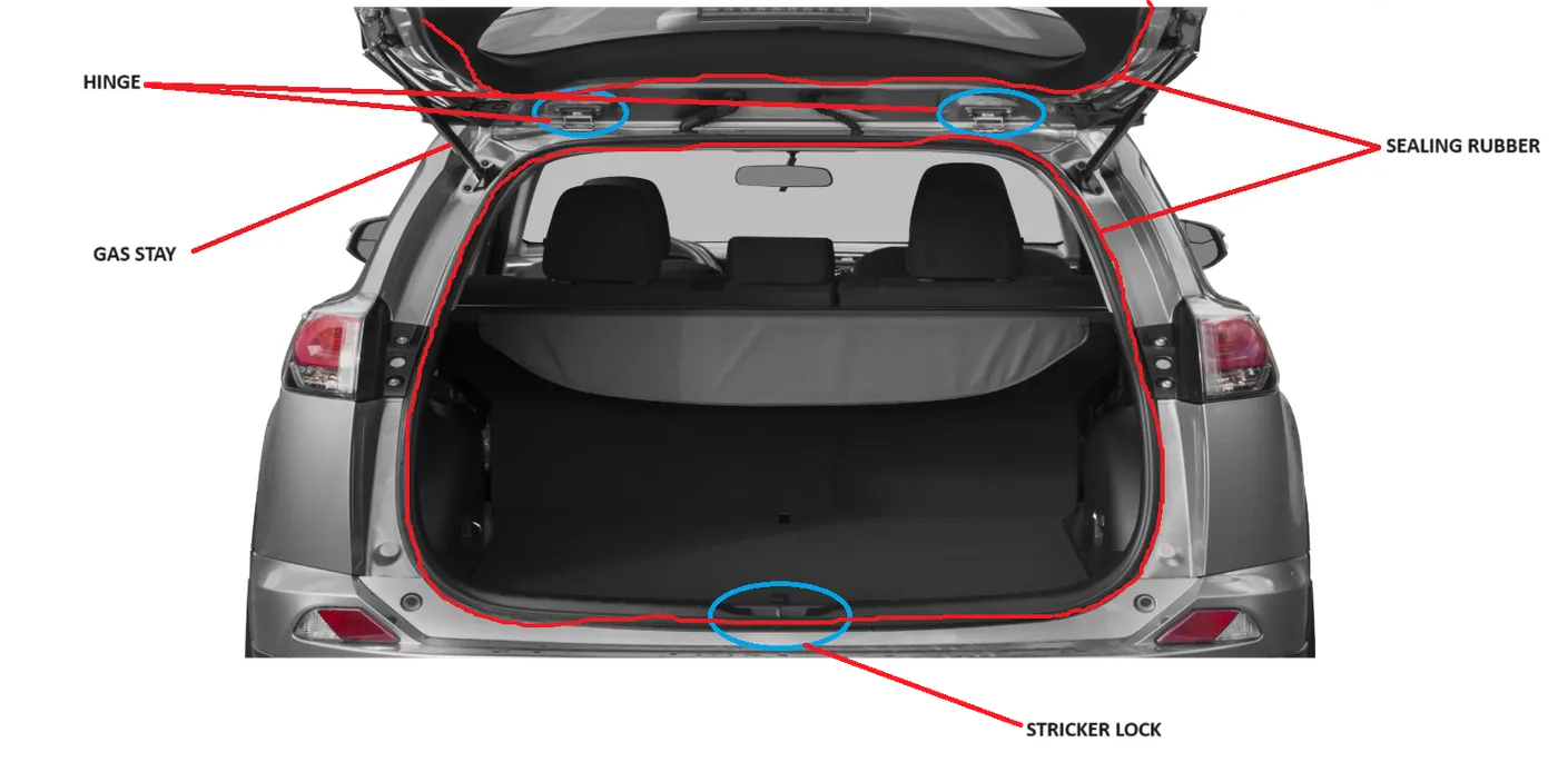
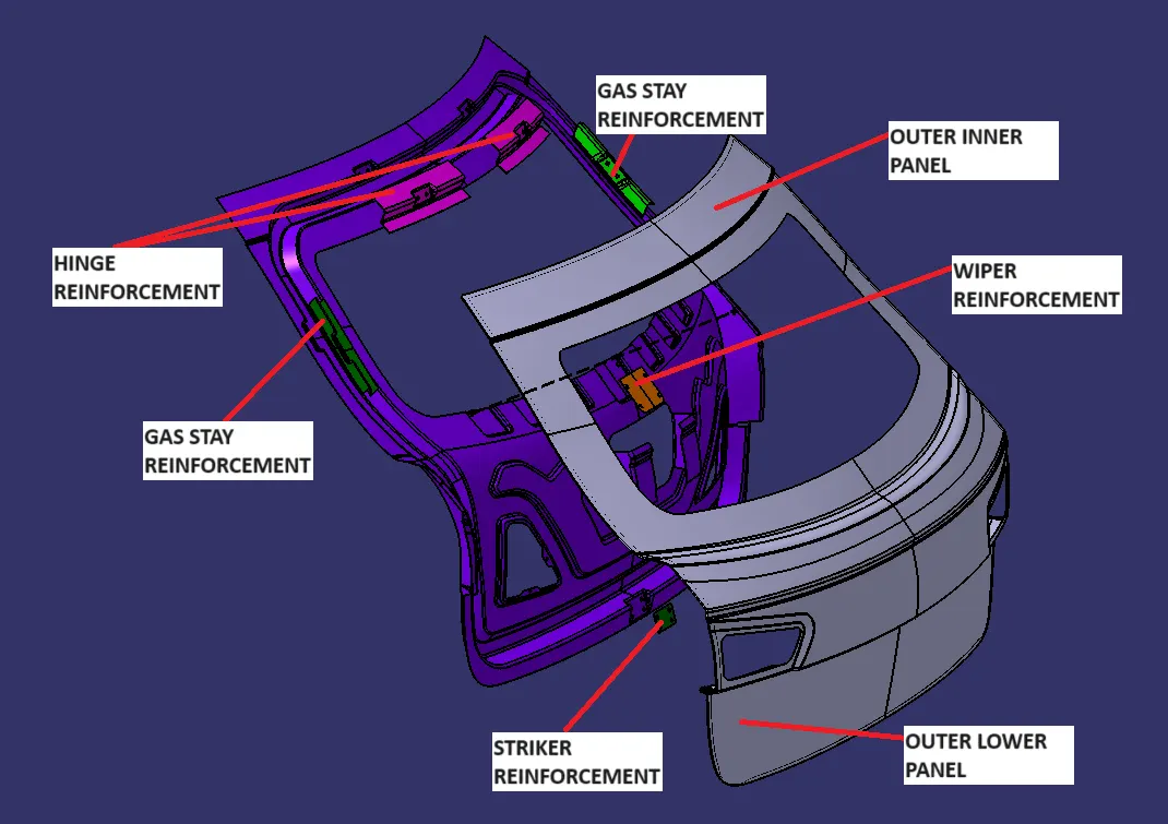
COMPONENTS OF BACKDOOR:
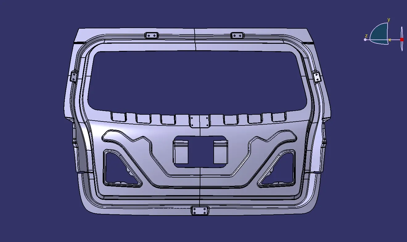
- Inner panel
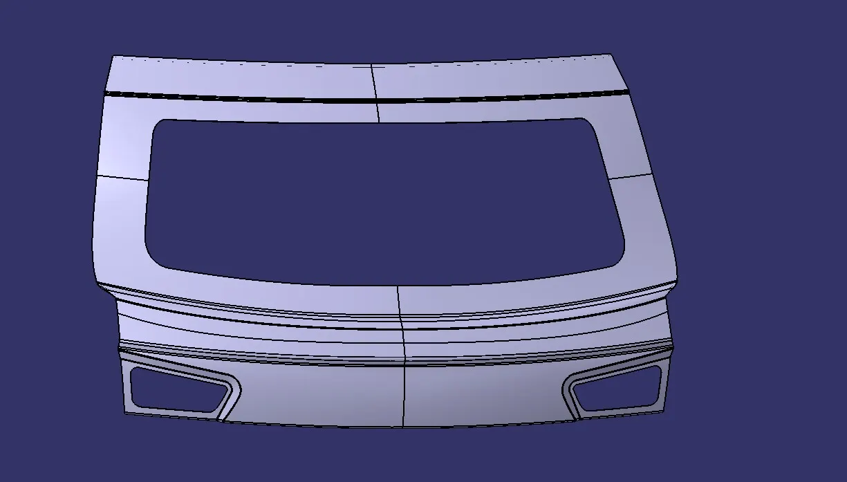
- Outer panel upper
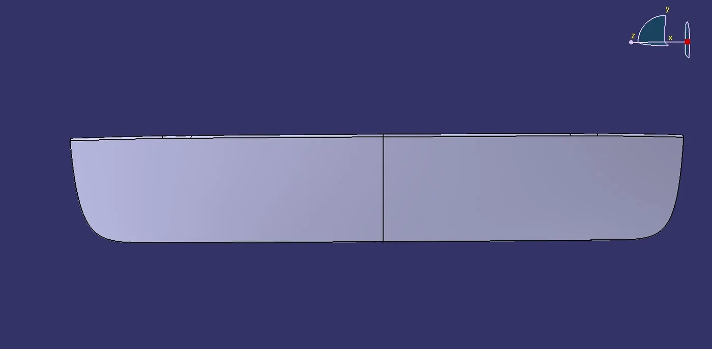
- Outer panel lower
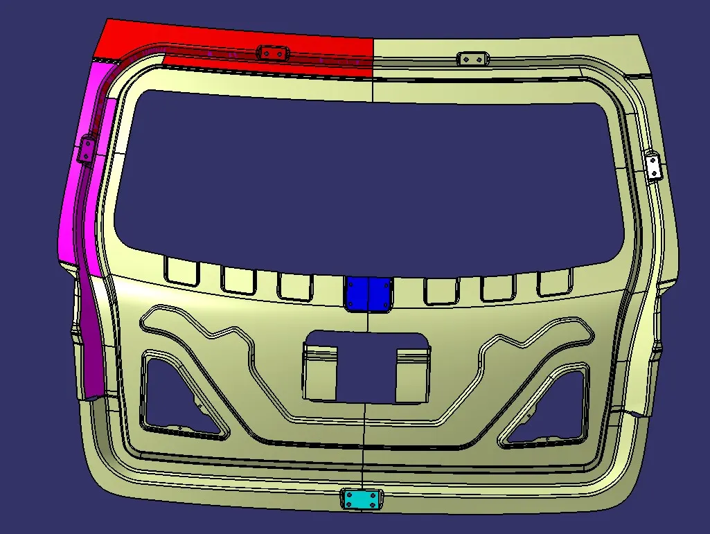
- Hinge reinforcement LH
- Hinge reinforcement RH
- Gas stays reinforcement LH
- Gas stays reinforcement RH
- Wiper motor reinforcement
- Latch reinforcement
DESIGN CONSIDERATION FOR BACKDOOR INNER PANEL:
- Rear Visibility.
- Support structures like hinges and gas stay.
- Mounts for wiper motor, tail lamps, and other wiring loops.
- Fit and clearances.
- Boot space
- Rear crash regulations and requirements.
- Sealing and its functions.
- Joining techniques like hemming, spot welding, Mastic Sealent, etc.
1. Functional Requirement:
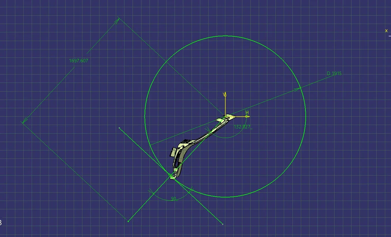
Hinge and gas stay are Functional Requirement.In order to design striker locks while closing the back door, first Position the hinge and create mid point b/w hinges. draw a circle and place stricker in such a way that it should trace the path of the circle. Depending on the position of gas stay and opening angle length of gas stay is decided.
2. Rear visibility criteria:
Federal motor vehicle safety standard (FMVSS) No. 111, “Rear Visibility,” currently requires that vehicles be equipped with rearview mirrors to provide drivers with a view of objects that are to their side or to their side and rear.
3. Requirement of sealing and its function:
In order to prevent water entering into the cabin we are introducing a sealing area where the sealing flange is provided on the inner panel and rubber mounting area is provided on the body side.
4. Joining techniques:
To join inner and outer panels the Hemming process is used and to join outer upper and lower panels laser brazing welding is used.
5. Gap and flushness requirement:
Mastic Seals place b/w Inner and outer panel to reduce Noise, vibration, and harshness. Every Mastic will have an effect of 80mm Dia locally. Inner and outer panel gap is 2 to 5mm. 0.2mm gap is required for from the Hemming and that gap will filled by sealed past.
6.Adding reinforcements and stiffener pad:
reinforcements are added where and all the weight is added. On the inner panel we have Hinges and striker, which are attached to the inner panel so due to this attachment the strength of the inner panel is going weak. In order to strengthen the inner panel reinforcements will play a very important role. Stiffener pad is the sponge-like material place b/w Inner and outer panel to reduce vibrations.
7.laser brazing welding:
Joining methods, in which the brazing solder is melted with the help of an industrial laser, have been used mainly in the mass production of vehicle bodies. There, laser beam brazing is mostly used for joining galvanized metal sheets or lightweight components made of aluminum, but also for other brazing material. Laser automobile brazing is usually realized with a brazing optic that is integrated in a robot. The laser beam is guided along the joint where it melts the brazing solder
Let's move on to the design the back door first we have to Begin by importing the provided styling surface into CATIA V5. This surface will serve as the basis for our back door design. Analyze the provided styling surface to understand its curvature, continuity, and design intent. Identify key features such as character lines, curves, and surface transitions.
OUTER UPPER PANEL CREATION:
Initially, we will be creating the Outer Upper Panel by first importing the styling surface in CATIA V5.
Since the styling surface is having some issues, we need to fix this by creating a new surface in place of the irregular surface.
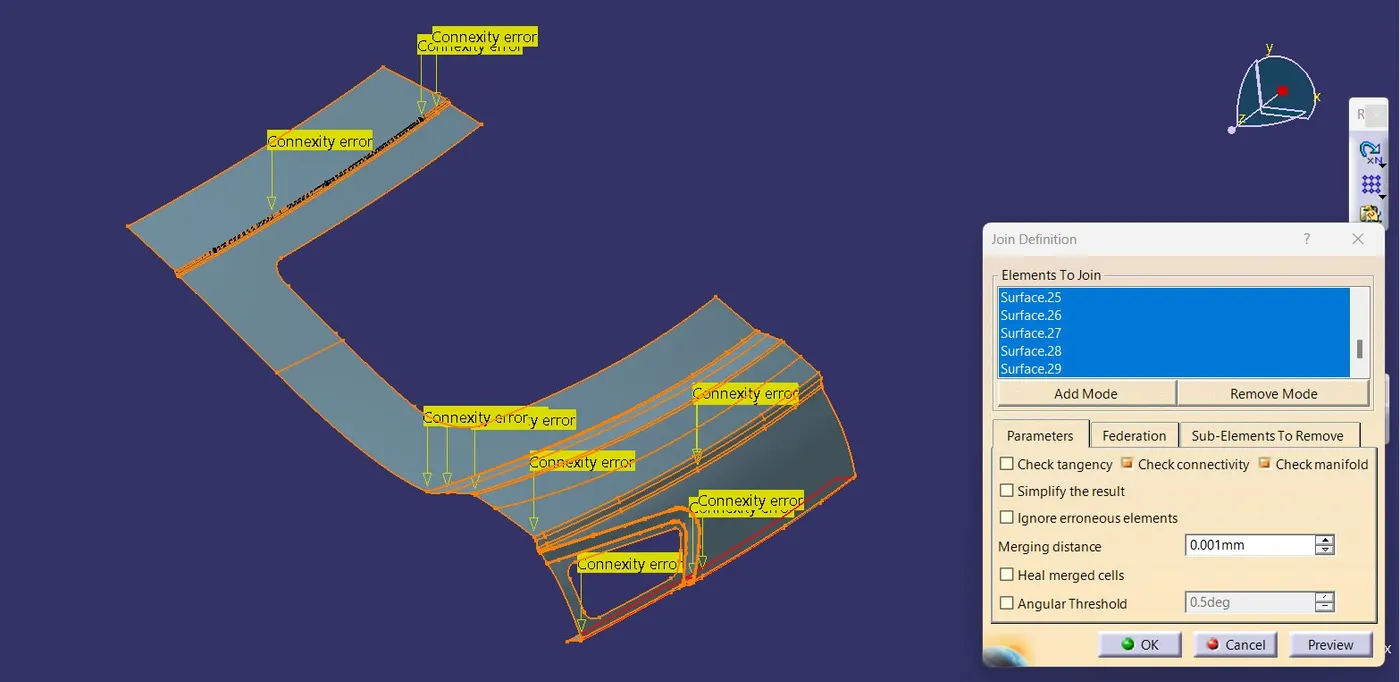
The surfaces can be created with the help of Multi-section, Extrapolate, Bi-Tangent Fillet & Spline and then the necessary fillets are provided to the sharp edges.
Once all the fillets are done make sure to check if the outer panel is offsetting/thickening to the required limit.
If the outer panel is not thickening due to sharp edges then we need to provide a bigger fillet value to avoid the sharp edges. image shown below.
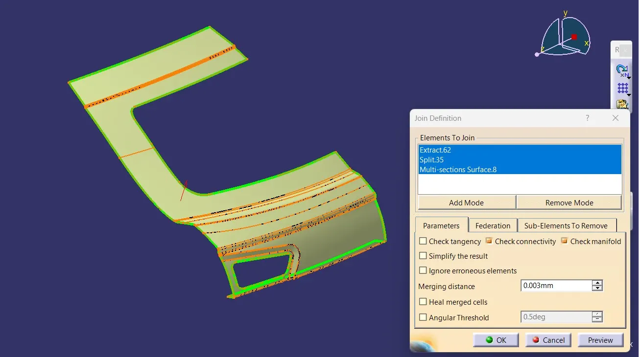
A tooling axis is also created in a direction through which most of the surfaces of the Back Door Panel are clearing the draft direction. This is done to make sure the part is manufacturable & clear the draft analysis. image mention below.
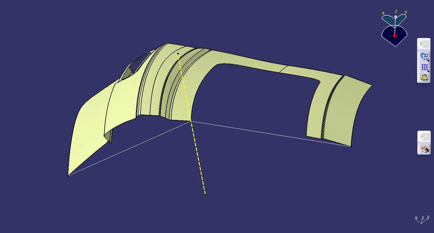
INNER PANEL CREATION:
First, offset the outer panels to 1.7mm downwards (Outer Panel Thickness=0.75mm downwards & Inner Panel Thickness=0.75mm upwards, and a clearance of 0.2mm is maintained).
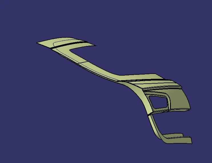
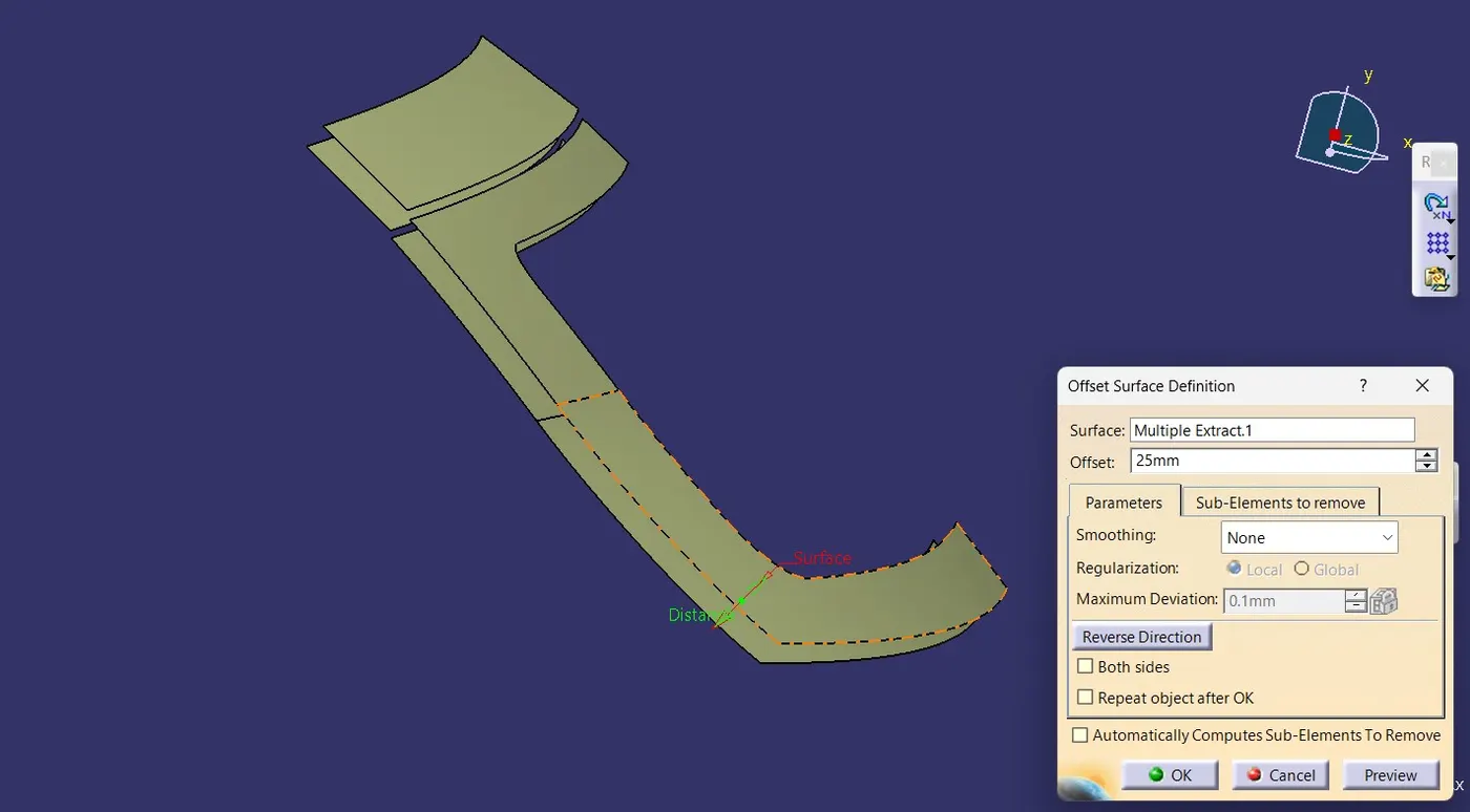
Now offset the outer upper panel to 25mm downwards and use the parallel curve option to cut the elements (to create a Sealing Flange) as shown in the below figure.
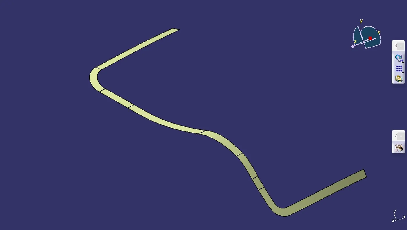
Join the Sealing Flanges by creating a surface between them using Spline & Multi-Section Surface. image mention below.
Using the Sweep option, create a surface with an angle of 37 degrees with the tooling axis. image mention below.
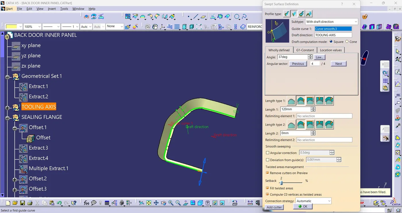
Using the offset surface of 1.7mm, trim this sweep surface. image mention below.
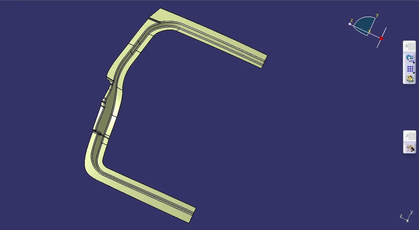
Now to create the windshield area of the inner panel, extract the surfaces nearer to that area from the 1.7mm offset surface. Sweep the sealant flange inner edges with an angle of 20 degrees inside and trim it with windshield extract.
join all the Surfaces using Bi-Tangent Fillet.
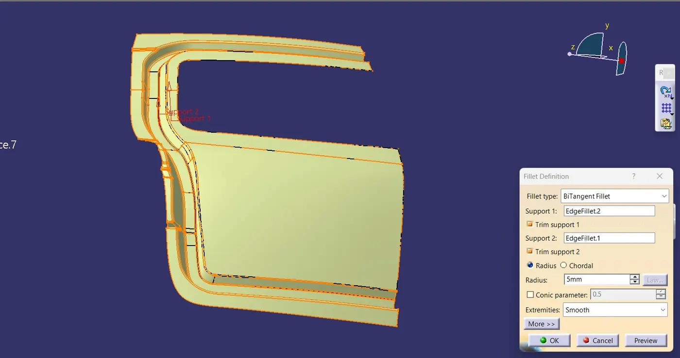
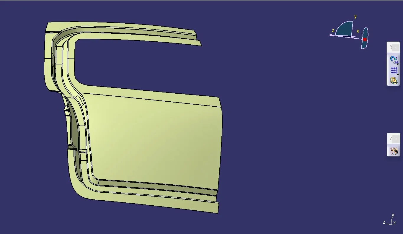
Similarly, create the lower side surface using the spline & multisection option and join them.
EMBOSS CREATION:
To enhance the crash resistance of the Back Door Panel, embossments are strategically positioned below the windshield area. These embossments are designed to mitigate the impact forces during collisions, thereby minimizing potential damage to both the vehicle and its occupants.
Enhancing Crash Resilience: Implementing embossments beneath the windshield area on the Back Door Panel to bolster crash resilience, mitigating impact forces for improved occupant and vehicle safety.
Improving Impact Absorption: Utilizing embossments below the windshield area of the Back Door Panel to enhance impact absorption during collisions, reducing potential harm to occupants and vehicle integrity.
Strengthening Collision Resistance: Introducing embossments in specific areas beneath the windshield on the Back Door Panel to strengthen collision resistance, safeguarding occupants and minimizing structural damage.
Enhancing Crash Performance: Incorporating embossments below the windshield section of the Back Door Panel to optimize crash performance, ensuring effective energy absorption and reducing impact-related risks.
Optimizing Safety Measures: Implementing embossments strategically beneath the windshield area of the Back Door Panel to optimize safety measures, enhancing vehicle crashworthiness and protecting occupants in the event of collisions.
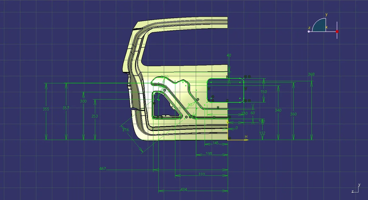
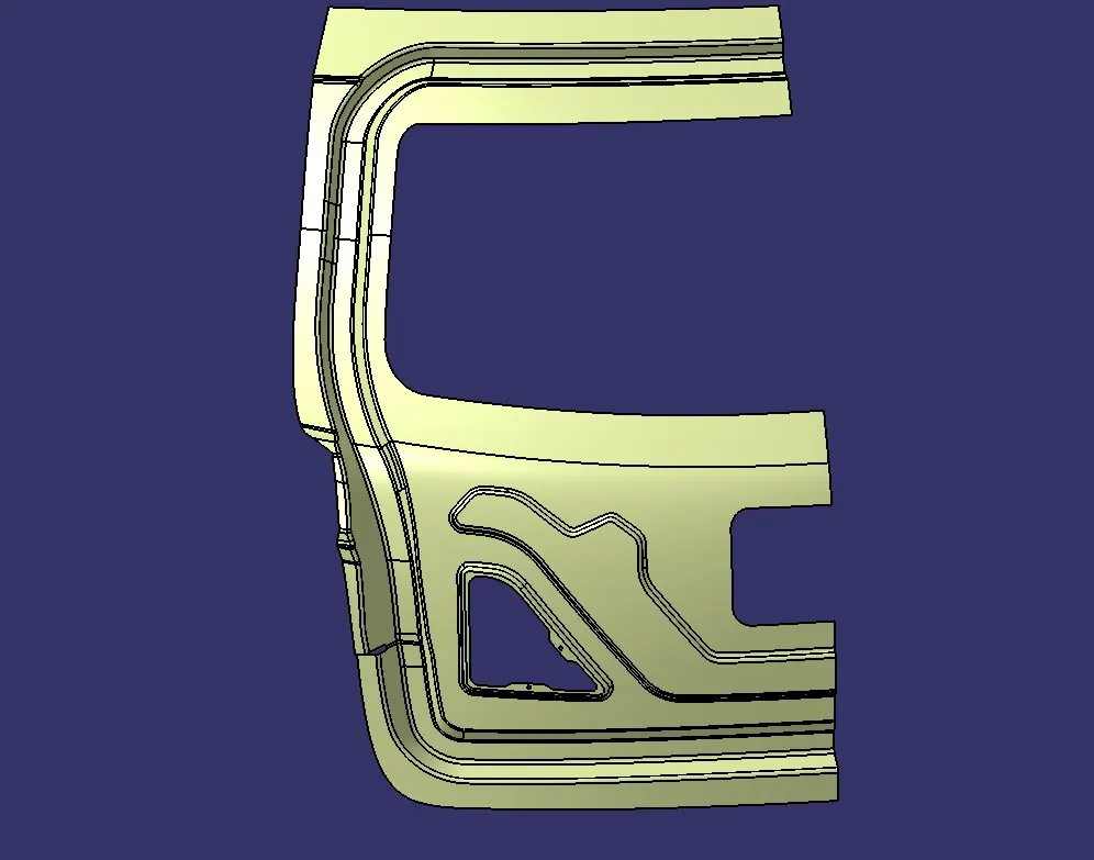
Project this sketch on the surface and split the surface using it.
Sweep the edges inside and using its base surface, trim these sweep surfaces to form the embossments.
PREPARING A SURFACE TO APPLY MASTIC SEALANT:
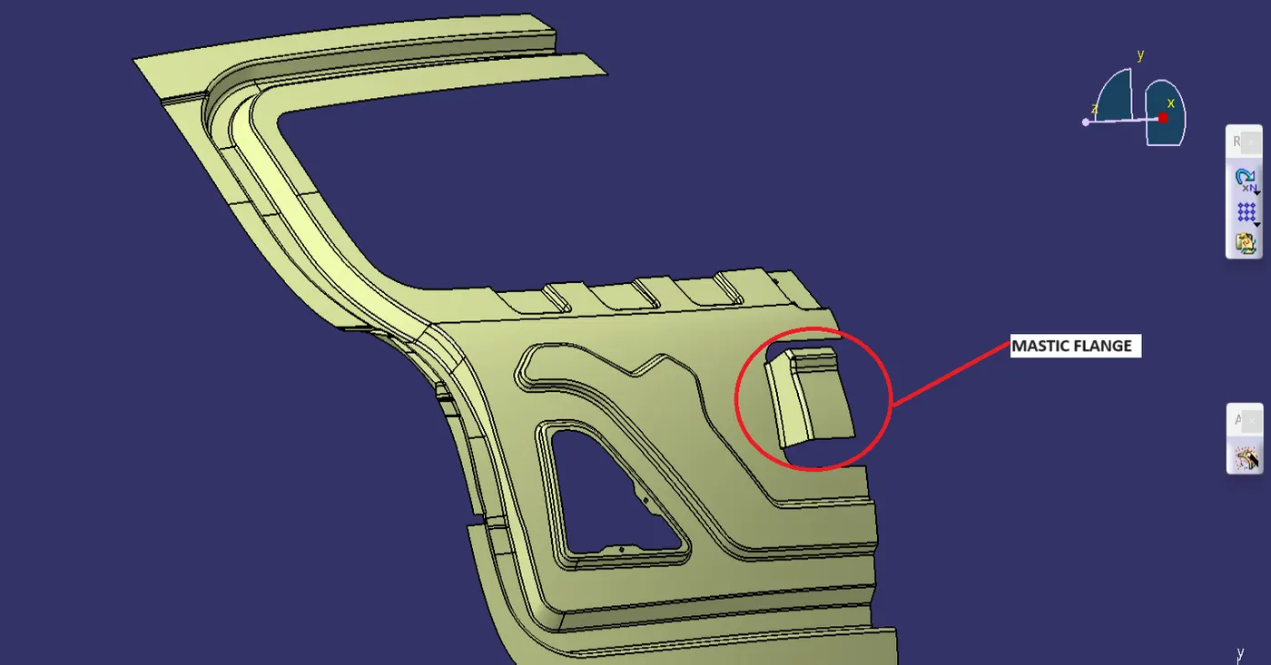
To apply the mastic, we need a surface which is having a 5mm clearance with the outer panel.
A cutout of rectangular shape is provided below the windshield area and using its edge a surface is created perpendicular to its base surface.
Now to create a surface for applying mastic first, offset the outer panel surface to 5mm.
Trim the outer panel with the sweep surface and remove the excess portion of the mastic surface by using the split option.
HINGE AND GAS STAY EMBOSS:
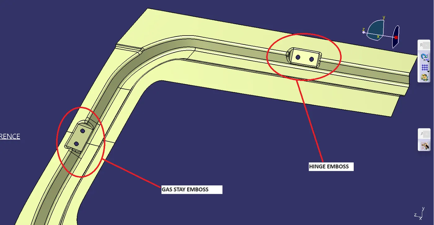
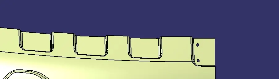
Hinge and Gas Stay Embossment is created at the sides of the inner panel by following the same procedures as mentioned in the case of windchill surface embossments. image mention below.
WIPER EMBOSS:
Wiper Embossment is created at the sides of the inner panel by following the same procedures as mentioned in the case of Hinge and Gas Stay Embossment. image mention below.
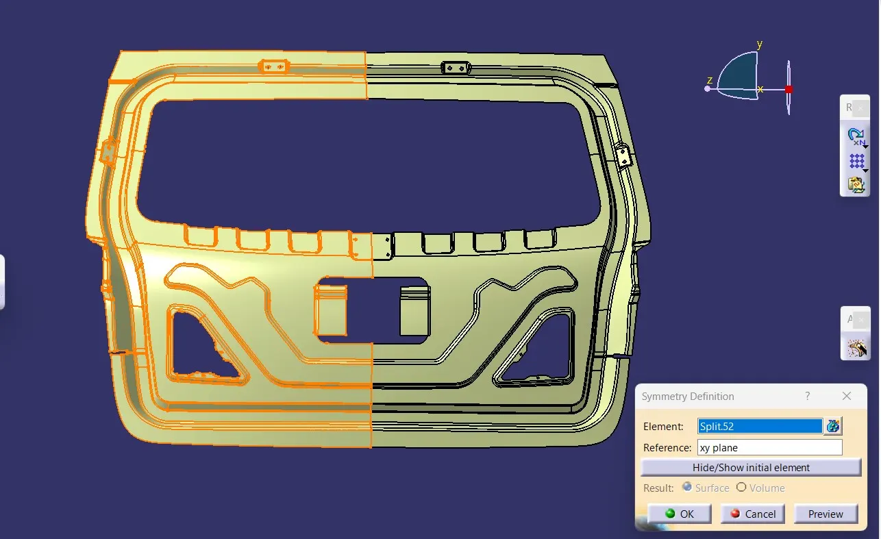
Now after working on all the required features do a Symmetry of the Inner Panel using the midplane as the reference.
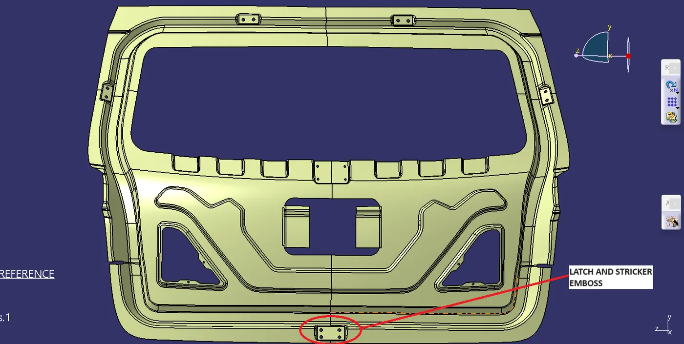
LATCH AND STRICKER EMBOSS:
Take create a center point between the two hinge parts and draw a circle marking the sweep of the lower end of the inner panel. Draw a Tangent to the Circle and create the cut on the tangent area and give the cutouts to it. image mention below.
Now draw the sketch on the plane where the circle intersects the inner panel lower side or where the latch follows the trajectory properly.image mention below.
HEMMING CREATION:
Hemming is a forming operation in which the edges of the sheet are folded or folded over another part in order to achieve a tight fit. Normally hemming operations are used to connect parts together, to improve the appearance of a part and to reinforce part edges.
Now to create the Hemming portion for the upper panel, offset the outer upper panel to 2.65mm downwards (considering the thickness of both outer & inner panels as 0.75mm and providing a clearance of 0.2mm).
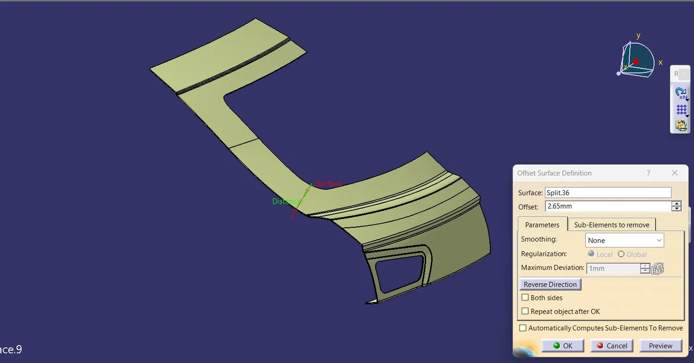
Offset the outer edges of the offset surface to 8 mm using the parallel curve option.
Split the offset surface with the offset curve & make sure to check whether this surface is thickening or not. This is done to make sure the surfaces won't create any problems while thickening at the end.
Now make a sweep by extracting the Boundary as Guide Curve & Reference Surface as the outer panel at an angle 90deg with a length of 3mm. image mention below.
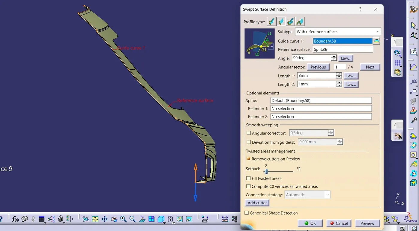
As there will be some angular discontinuities in the sweep we need to rework and make it into a tangential surface then only we can get the hemming of the Outer panel. So, where and all the surface is not good we need to Split that part and do a patchwork with the multisection surface.
Give a Tri-Tangent filet by selecting these 3 surfaces. (Outer panel, Sweep, Outerpanel Offset). image mention below.
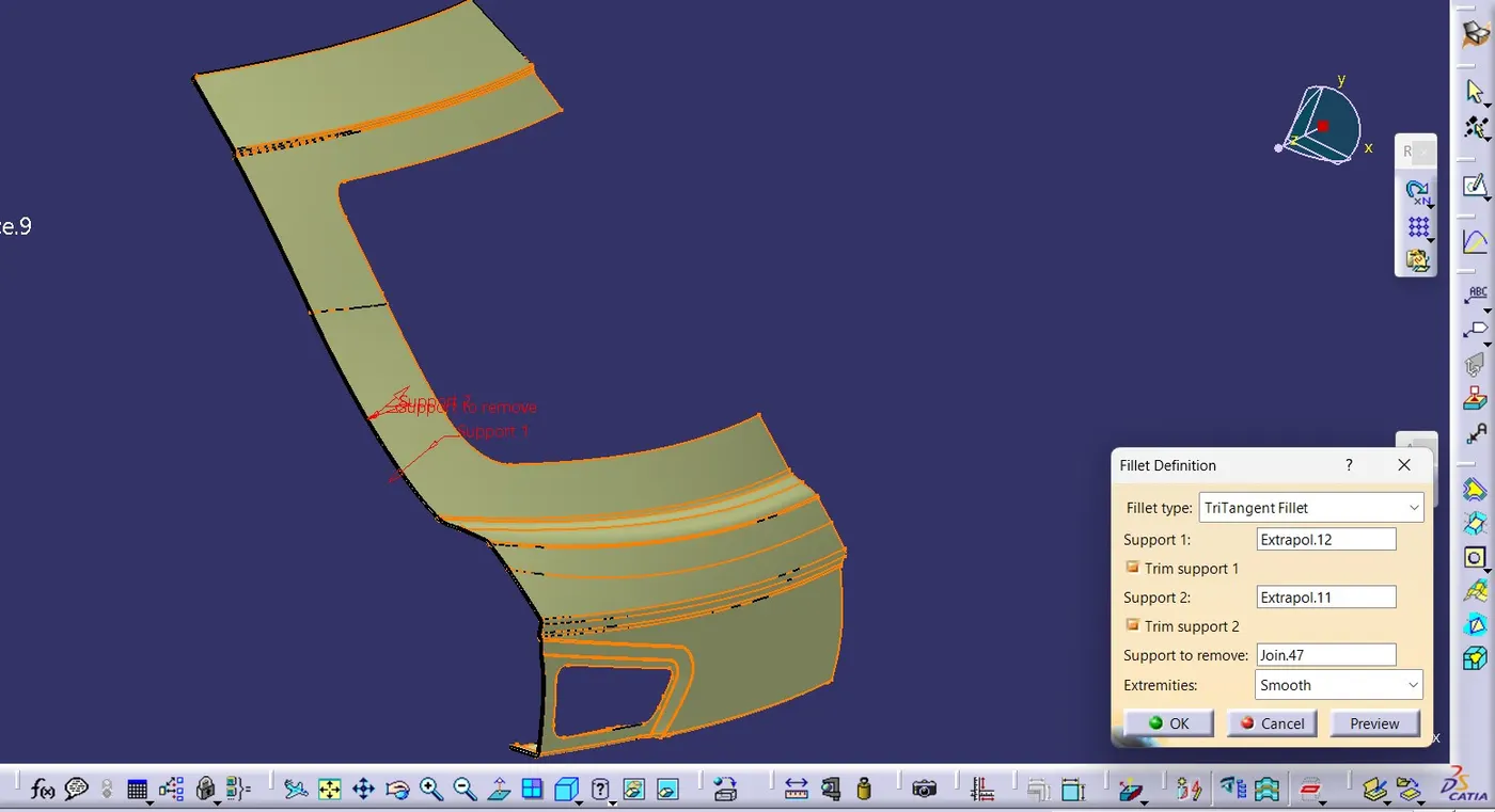
Near the corner, we will be providing relief. This will be done with the help of a parallel curve/Sketch, spline & split options. Using the relief curve and split the surface to form a relief at the corner. image mention below.

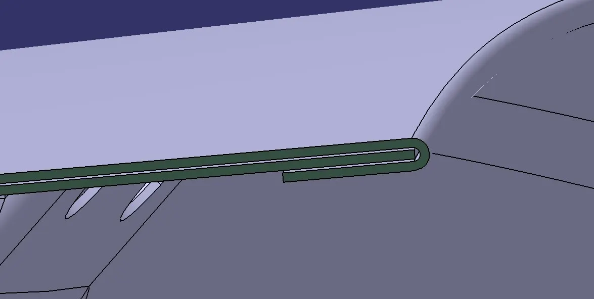
REINFORCEMENT:
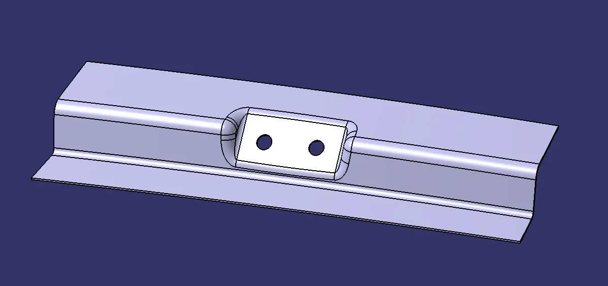
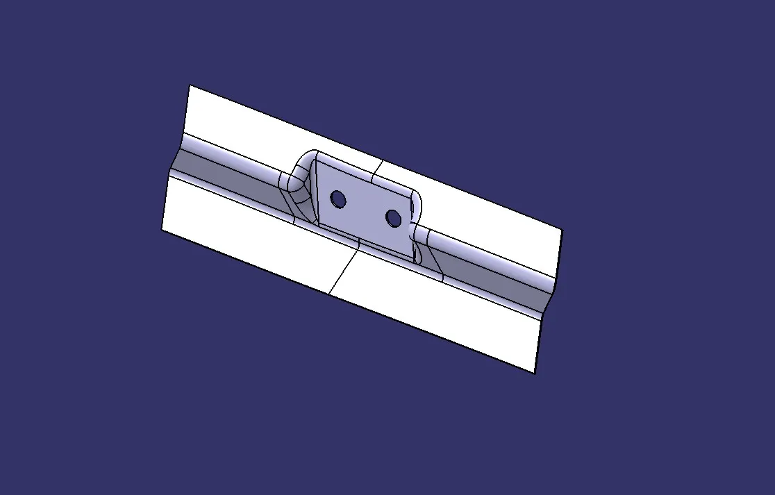
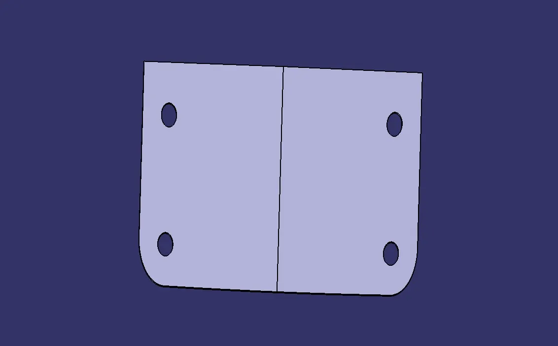
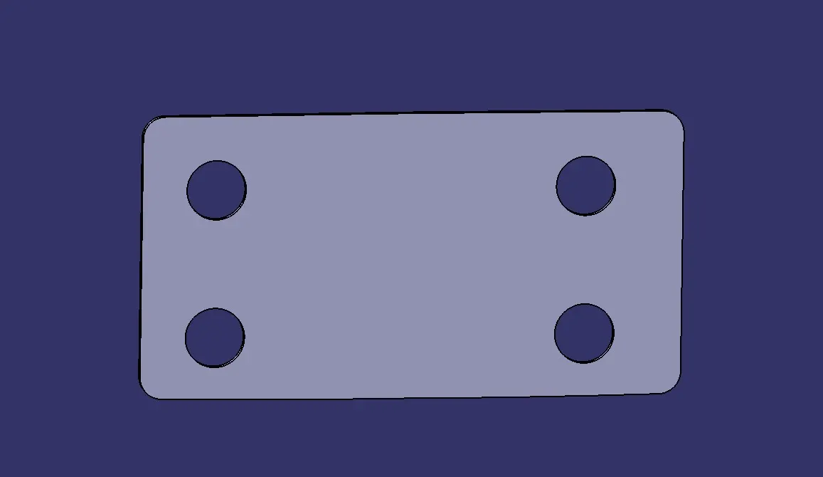
To create the reinforcements, select the surfaces with the nearby areas and extract them. Cut the excess portion by first creating a line on the surface and then splitting the surface using it. image mention below.
SOLID BODY CREATION:
Use the Thick Surface option in Part Workbench to generate the solid. The thickness for all the components of the Back Door Panel is given below.
Outer Upper Panel: 0.75mm (Thicken Downwards)
Outer Lower Panel: 0.75mm (Thicken Downwards)
Inner Panel: 0.75mm (Thicken Upwards)
Reinforcements: 1mm (Thicken Upwards)
OUTER PANEL UPPER:
OUTER PANEL LOWER:
INNER PANEL:
HINGE REINFORCEMENT:
GAS STAY REINFORCEMENT:
WIPER REINFORCEMENT:
STRICKER REINFORCEMENT:
DRAFT ANALYSIS OF INNER PANEL OF BACK DOOR:
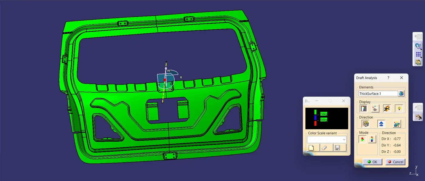
In the draft analysis all the surface was clearing the draft angle of 7 deg. with respect to tooling axis.
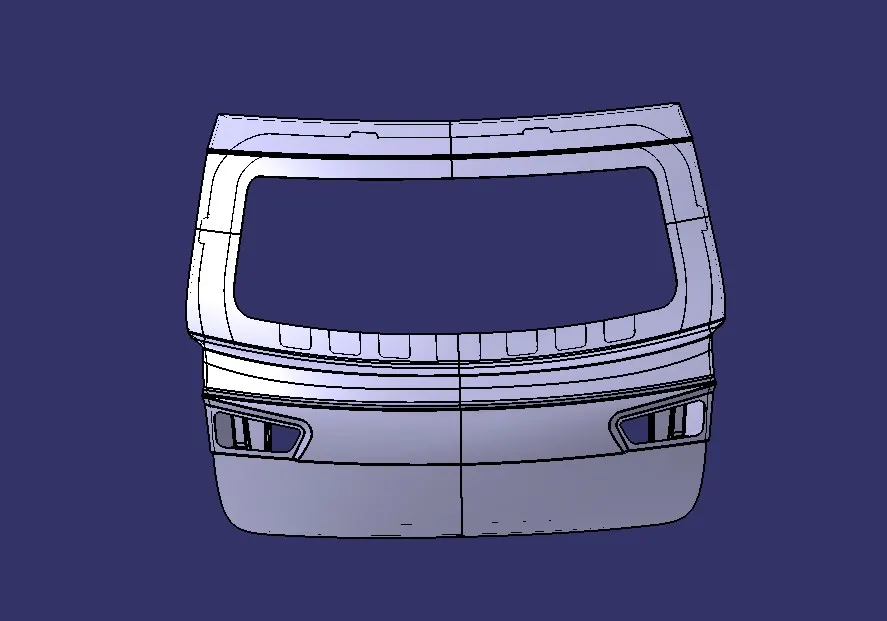
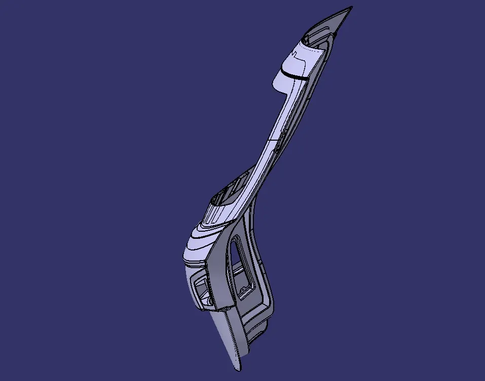
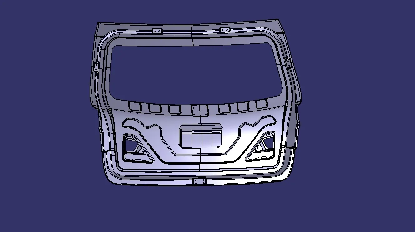
OVER ALL OUPUT OF BACK DOOR DESIGN:
CONCLUSION:
The sheet metal part body of the hatchback car's backdoor was effectively engineered, incorporating key features such as embossments, hemming, and suitable draft angles to ensure manufacturability. The design approach for the inner panel was strategically chosen to redirect forces outward during crash tests, optimizing safety and structural integrity.
I can't upload the zip file in the given box it shows only under 20MB file will be applicable so, my file is above 20MB its around like 50MB. so, I provided the google drive link below.
Back door design google drive link: https://drive.google.com/file/d/196bG1a9bVcQcRTpeVXr4CsDIMDfJWtvz/view?usp=drive_link