Design of backdoor
Objective:
Use the provided styling surface to come up with a back door design, use appropriate design methodologies, and provide the necessary reinforcements and embosses.
Back Door:
The back door is a hinged door/tailgate at the rear of the vehicle. It may be used for loading and unloading cargo, or to get passengers in and out, in case there are seats present at the rear. The back door comprises of certain components which form the back door assembly together.
- It is also known as the trunk or boot of a Car. It is also called a tailgate.
- In India the storage area is known as a dickey.
- Back doors are one of the type doors of the vehicle which are located next to the rear passenger seat which provides access to the luggage compartment.
- In most of the cars, these back doors are operated with the help of gas stay which in turn reduces the effort required to lift open the door.
- Some luxury cars have powered backdoor which in turn is driven by an electric motor. This kind of system is also called a powered trunk lid system.
- Some trunk are open with the help of guester moments and sensors with out any physical button or hummon effort.
- Hatchback or station wagons are sold as 3 door or 5 door models. In this case, the rear hatch is classified as door this is because it enters the passenger compartment.
- In some model cars like Sedan the Back door is separate space that has no link with the rear passenger rows.
- In Top model cars it is used as the storage of foldable roof in convertable models in luxary models.
Its main functionality is
- To get into automobile rear side , Passengers entry to the rear rear row:
- In the SUV and MUV models the backdoor is the acess to the rear sitting or 3rd row sitting for passengers.
- In the 3 door models like Mahindra Thar is also having the back door acess for Passengers.
- To carry the cargo or luggage:
- The primary functionality of the trunk or backdoor of an automobile is to provide a secure and enclosed space for storing luggage, groceries, sports equipment, and other cargo. This compartment is typically located at the rear of the car and is designed to be separate from the passenger compartment, providing additional storage space without compromising passenger comfort or safety.
Design Considarations:
- Length:
- It is one of the main to cosider , if the length increases hen the Taxes and cost manufacturing also increases.
- It also helps in the asthatic appreance of the Automobile.
- Storage Space:
- It is the majorly considered for the luggage storing for travelling, Transporting etc.....
- For the top models it is mandetory to have the minimum of 300Lrt of space in it.
- It is also helps in the keeping of Spare tyre or Stepne and the tool box and first aid kit .
- Safety :
- It is also to be considered in the crash or Accident.
- The sensors are also placed in the rear side , if the impact happens to blown and alert the airbags
- It is absorbs the impact energy that the emboss are created.
- Rear Lighting:
- The tail lights and side indicators are fixed on the backdoor for the safety measurements.
- In application of sudden brakes or slowing down of automobile these lights will help the other vehicles to be alert .
- The rear side indicators will helps the other Automobiles about the precaution of the vehicle turning.
- Rear Glass:
- This helps while moving the vehicle reverse mode.
- These helps to look the blindspot of long vehicles in the rear mirrors.
- In some automobiles it also helps in the ventilation , mostly in the offorad vehicles.
- Wiper :
- It is helpful to the drives to get more visibility in the rainy and snow climatic conditions.
- Soe models have the water sprayed in the rear wipers to clear the dust.
Types of backdoor on working position:
The back door is mainly classified into three types based on the its opening position
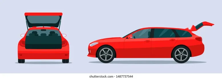
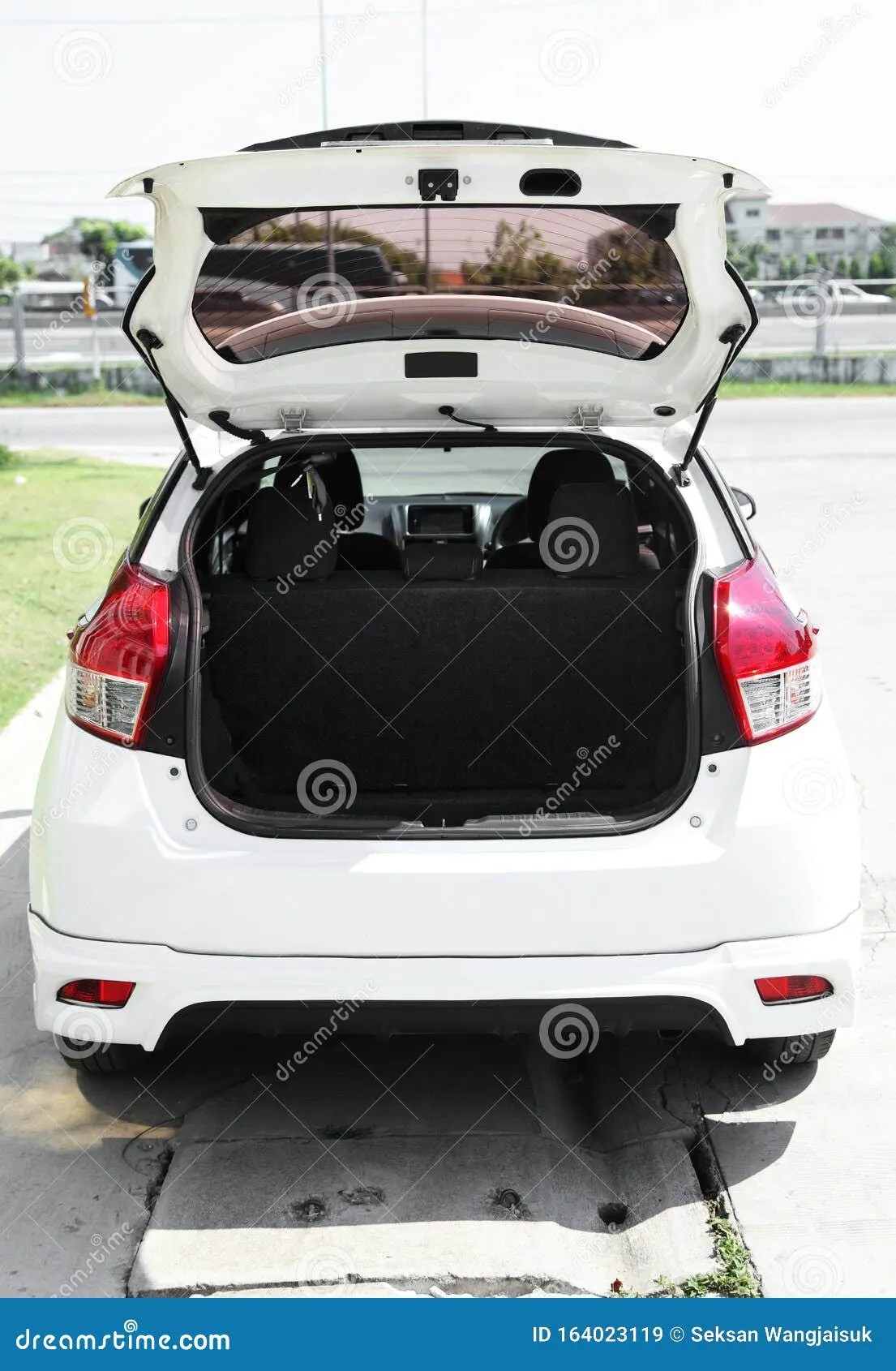
1.Top mounted:
- This type of back doors is used in a station wagon, pickup trunk and some of the spot utility vehicles.
- Today's modern cars use top mounted tailgating system which are both powered and also gas stay supported.
- These top mounted tailgates provide greater rear visibility compared to side mounted or backdoor which have center pillars in it.
2.Side mounted door:
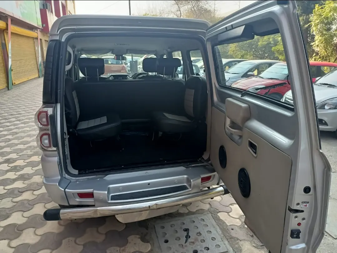
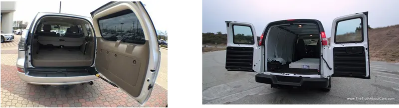
- As the name signifies the side mounted doors are the one which is used in the van type MPVs, SUVs, pickup truck vehicles.
- These side mounted doors or barn doors are a lot easier compare to top mounted doors.
- These doors are generally smaller in size and can be easily accessed.
- These doors are more convenient for the goods handlers for long pipe and lengthy components where one door is kept open.
- These door also save accidental head impacts.
- It is a lot easier to load and unload items in the side mounted doors.
3.Bottom type:
- This bottom type type backdoor system are used in the car type such as car, pickup truck and some luxuary SUVs.
- These are the most convenient type of back door in which the bottom split is used as a support or even as a table for the tour going people.

Its opening is maily classified as follows
- Gas Stay:
- It is a support system that has the gas filled chambers in it.
- It is operated manually , when we give a initial push or efforts it is operated.
- Electric Motor or Power Train:
- It is electrically operated with the help of the sensor button on the Key Fab
- Or a buttion or switch inside the car.
- Guesturs :
- These are similar to the Electrically driven but the opening mechanism is also controlled by the help of gesutures moments for easy acessability.
- These are provided in the top brands and luxary models.
manually closing with help of gas stay


Guesture operated back door

Methods of Manufacturing Back Door
This is the sheet metal component with the tickness of 0.75mm. These are manufactured industrially mainly by these methods,
1. Dep Drawn Method:
The metal deep drawing process is an effective method of manufacturing of Sheet like components to the products. The process involves a punch with a round comer and a die with a large radius. The punch-die clearance is slightly larger than the thickness of the sheet metal to be deep drawn. As the load applied through the punch, the sheet metal is forced to flow radially and sink into the die cavity to form a cup. The process is best suitable for complex shaped problems. The deformation is not even throughout of the blank. Due to the biaxial compressive stresses, the flange gets thicker while, the vertical wall gets thinner, due to the uniaxial tension, failure is expected at the location of maximum thinning.
There are mainly two stages in the Deep Drawing
- First- stage drawing: The blank shape of metal is placed on the die and contact with the punch. When the metal specimen is flat piece of sheet metal used in forming and finish the product. Initially the punch moves in downward direction. The outer rim of blank is subjected to pure radial drawing (drawing toward in vertical axes) between die and blank metal. The metal become a bend and sliding over die and also stretched between die and punch. The metal in vicinity of punch head and contact with it bend and slide over radii and stretch over punch head.
- Redrawing: The components drawn from first stage again it is redrawn convert into more depth to form a cup shape in the die and punch. The second stage of drawing is called as redrawing.
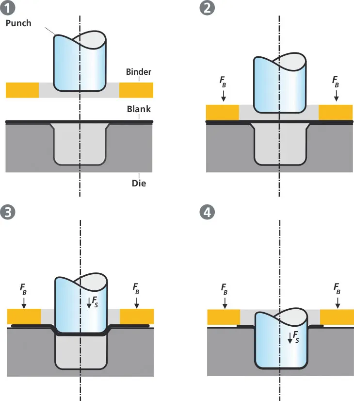
Steps involved in the Deep Drawn
- Bending:
- As the application of load starts, the blank is first bent onto the round edge of the die cavity.
-
Straightening:
-
Now, with further increase of the load, the bent part of the blank is straightened in order to sink the annular punch-die clearance. The result is a short, straight, vertical wall formation.
-
- Friction:
- The rest of the blank starts to flow, radially and to sink into the die hole. But the frictional force between the lower surface of blank and upper flat surface of die, try to impede that flow. The magnitude of frictional force drops as the blank metal starts to move.
- Compression:
- The blank undergoes compressive stresses. The width of the sector shrinks so that the larger perimeter of the blank can fit into the smaller perimeter of the die cavity.
- Tension:
- The applied load is increased, almost all the metal blank sinks into the die cavity, thus forming a long vertical wall. The remaining blank part takes the form of a small annular flange. The vertical wall is subjected to uniaxial tension.
2. Stamping Process:
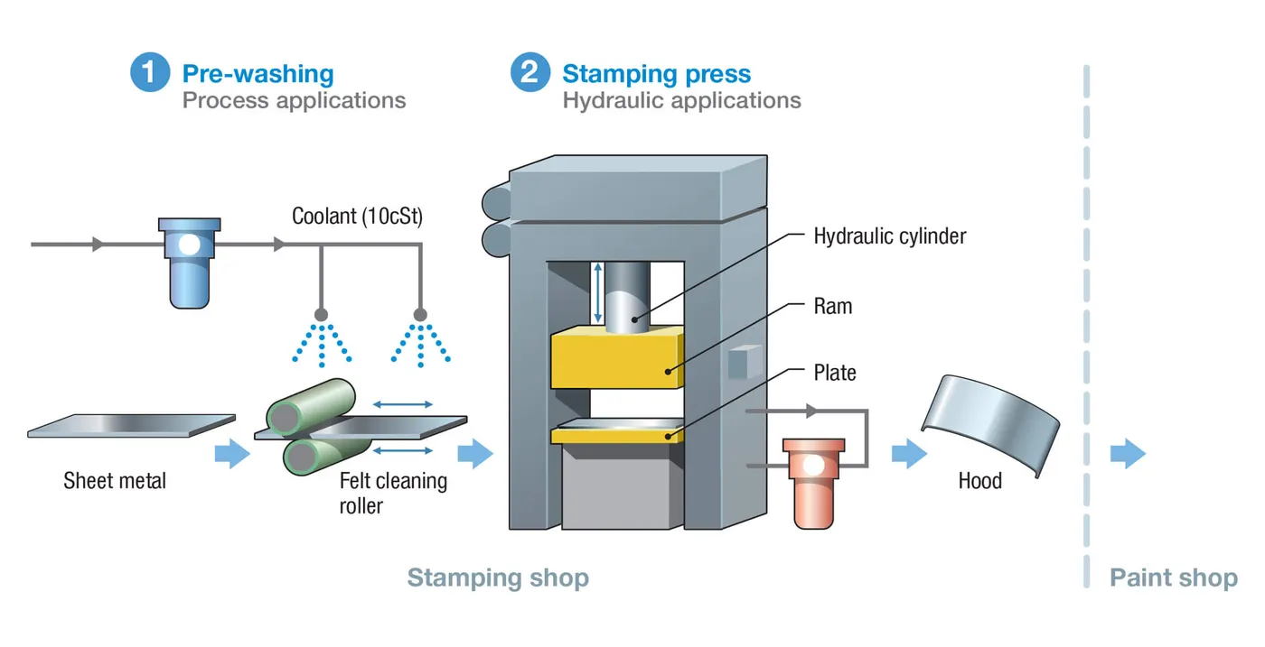
Metal stamping is a cold-forming process that makes use of dies and stamping presses to transform sheet metal into different shapes. Pieces of flat sheet metal, typically referred to as blanks, is fed into a sheet metal stamping press that uses a tool and die surface to form the metal into a new shape.
Common Metal Stamping Processes
- Blanking
- Banking is the first step of the stamping process. Blanking is the process of cutting larger sheet or coils of metal into smaller, more manageable pieces.
- Blanking is usually performed when a stamped metal piece will be drawn or formed.
- Piercing
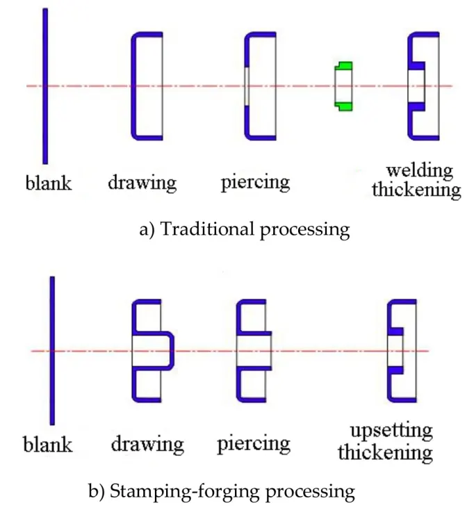
- If a part requires slots, holes, or other cutouts, piercing can be employed.
- Piercing, which can be performed simultaneously with blanking, punches the requisite shapes out of the metal sheet.
- Drawing
- Drawing is the actual stamping in the metal stamping process.
- A punch forces a section of metal through a die, providing the primary shape of the part.
- When the depth of the part is less than the primary opening, it is considered shallow drawing, parts with a depth greater than the opening are deep drawn.
- Bending
- Bending is a fairly self-explanatory process.
- The part-in-progress is placed on a specially designed die and a ram pushes against the metal, providing the required bend.
- Bending is performed after drawing, as attempting to punch an already bent piece of metal causes the entire part to deform.
- Air Bending
- Air bending is when the flat surface of a part is bent by a punch into a die, often V-shaped.
- The space between the punch and die is larger than the metal thickness, resulting in a bend that relaxes slightly when the part is released.
- Air bending uses less power and pressure than other bending methods.
- Bottoming and Coining
- Bottoming and coining are bending processes are similar to air bending, but use anywhere from two to 30 times the pressure and the material is forced fully into a tight-fitting die, resulting in a more permanent bend.
- Forming
- Forming is a bending process similar to bending, bottoming, and coining. It creates parts with multiple bends, such as U-bends, in one step.
- Pinch Trimming
- Pinch trimming is a method of cutting a piece from the metal sheet, separating it from the scrap metal. It is an unconventional process: the metal is pinched against a flat vertical surface. It is often, but not exclusively, used to cut deep drawn round cups from the sheet.
- Lancing
- A unique process, lancing is a type of metal cutting used to make vents or tabs. A section of a part is cut along three edges and simultaneously bent. This creates the opening or hook-like feature required but eliminates a scrap collection or secondary machining step.
Embossing:
Embossing is a metal forming process for producing raised or sunken designs or relief in sheet materials by means of matched male and female roller dies, theoretically with no change in metal thickness or by-passing sheet or a strip of metal between rolls of the desired pattern. Metal sheet is drawn through the male and female roller dies producing a pattern or design on the metal sheet. Depending on the roller dies used, different patterns can be produced on the metal sheet.Benifits of Emboss are
- It improves the strengthen the components.
- It increases the Area of cross section that increases the Moment of Inertia & Section Modulus to the component.
- If the sectrion modulus is high the it resists to the bending and twisting of component.
- It also helps not to deform the product ude to vibrations and Dampings.
- It is also helps to remove the excess material in the embossed faces to reduce the weiht of component.
- It helps in increase in strength ad reduction of weight.

Hemming:
Hemming is a common metalworking process mainly carried out to reinforce an edge, hide burrs or just improve the overall appearance of sheet metal parts. When hemming is carried out in a way that a joint between two sheet metal parts is created, it is called seaming but more on that later.
Hemming in sheet metal operations refers to the bending of a sheet metal edge onto itself. It is very similar to edge stitching in clothes. Similar to how an edge stitch strengthens the edge and makes it more durable, a hem imparts strength to the metal edge and improves its appearance. The edge of one part may also be folded onto another part to create a joint.
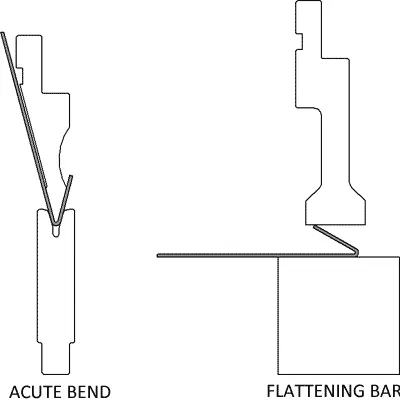
Hemming is usually done in two stages. The first stage creates an acute bend using acute tooling (V die) followed by a flattening of the return flange using a flattening die.
A complete list of hemming benefits on a sheet metal product is as follows:
- Hems strengthen the sheet metal edge
- They improve the surface appearance and surface quality
- They hide defects such as rough edges and burrs
- They can connect parts
- They make the edges safer to handle
The different sheet metal hems based on the hem shape are as follows:
Flat or closed hem
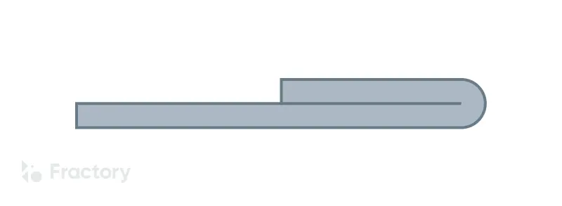
In a flat or closed hem, the part of the edge that bends sits completely flush over the rest of the metal sheet. The angle between the returning flange and the sheet metal is 180 degrees. The inside radius is zero and thus, there is no gap between the returning flange and the metal sheet.
Closed hems require a lot more power and tonnage from the presses than open or teardrop hems and it is also not advised for metal sheets that are over 2-3mm in thickness since the sheets are likely to fracture.
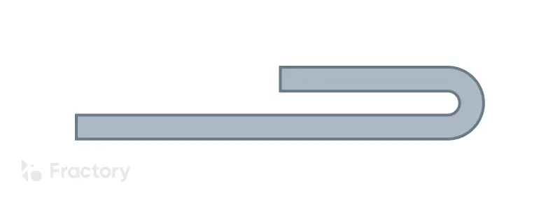
Open hem
In an open hem, the returning flange is folded over the sheet metal but there remains an air pocket between the two. The bend angle in this hem type is also 180 degrees.
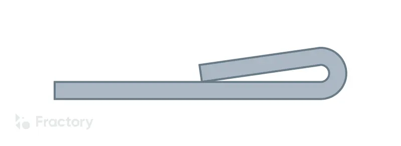
Teardrop hem
In a teardrop hem, the returning flange is bent beyond 180 degrees. The resulting shape resembles a teardrop.
It is perfect for materials that do not have the required ductility to provide closed hems. Teardrop hems are used for fragile materials such as aluminium.
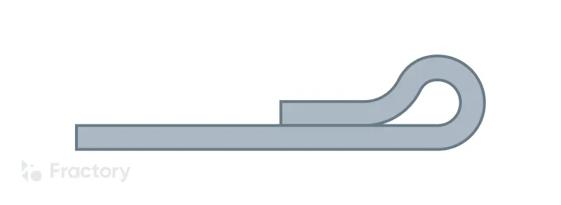
Rope hem
A rope hem has a returning flange at a bent of more than 180 degrees. Once the hem achieves the shape of an open hem, the returning flange is pressed onto the part surface through a flattening die.
The edge is bent in shape similar to an open hem and then the second piece to be connected is inserted into the gap between the metal sheet and the returning flange. Further pressing takes place making the second parts sit flush between the metal sheet and the returning flange and create a joint.
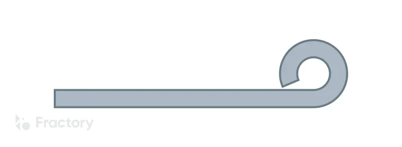
Rolled hem
In a rolled hem, the bent portion of the sheet metal is tucked back into itself. This creates smooth round edges all around for holding the part from the hemmed edges. This process is also commonly referred to as curling.
The hemming process can be carried out in one of the following two ways:
-
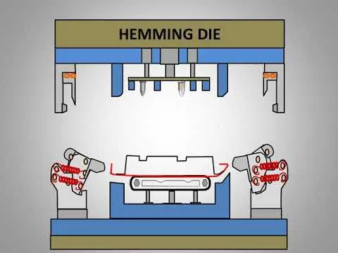
Die hemming
- It is the conventional hemming operation that uses a die and press to carry out hemming.
- In this process, the bending occurs along the full length at predefined angles in multiple steps. These steps are known as pre-hemming and final hemming.
- For instance, when forming a closed hem, the edge will be bent to 45 degrees in the first step by passing it through a press brake.
- The next bent occurs by means of the same press brake but a different part of the tool that completes the closed hem.
- The die hemming process is not very flexible and is generally restricted to the production of flat, uncomplicated panels.
- The investment in the equipment is high but the cycle times can be brought down to be quite low.
-
Roller hemming
- It is the process was invented to increase the flexibility of the hemming operation.
- It generally uses robots to control rollers that bend the edges but there are simpler manual roller hemming machines available that can handle only simpler tasks with less accuracy.
- The rollers travel along the edges and bend the part edge to the desired angle in multiple steps.
- The orientation of the sheet may be changed multiple times during the hemming process to reduce the travel of the roller and increase the cycle time.
- Apart from the robot itself, this method is considered economical both for low and high-volume tasks.
- Robot roller hemming allows for jumping back on forth between producing different parts through quick program changes.
TOOLING AXIS:
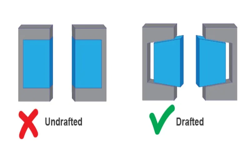
- It is the direction of Mold's Core & Cavity moves.
- The Tooling Direction is basically the direction that the mold pulls apart.
- The mold is built in two separate pieces, Cavity side & Core side.
- The Core pulls apart from the Cavity and that's the Tooling Direction.
- The Line of Direction or Axis followed is Tooling Axis.
- It is created by the given input surface by the Normal to the surface or bi-section method or moment of inertia method
DRAFT ANALYSIS:
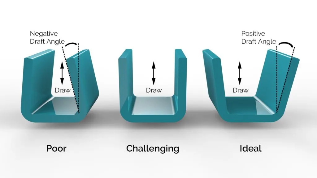
- The draft analysis technique is used to analyze whether our part model created is manufacturable or not.
- Based on the Draft condition and Tooling Axis applied, Here the part should get easily removed from the Mold (Core & Cavity).
- It increases the life span of molds and reduction of defects on deforming of parts while manufacturing.
- In the sheet metal design the minimum draft angle is 7deg.
Main componets of Back Door
- Back door inner pannel:
- These are the inner pannel that consists of all the interior components of hinges , emboss , gas stay atchments etc...
- it covers the outer pannel and its component slike wiring harness , tail lamp, mirror etc...
- The fabric sheet is atached to it towards the inner side for asthetically good
- Hinges
- These ar the attached to the inner pannel and car body(roof rail)
- These are alligned with the each other in a proper axs system.
- These helps in the opening and closing in the proper direction.
- Gas Stays
- These helps in the opening and closing of door
- It mainly holds the position of the door in the open condition
- It can be operated manually with initial effort or electrically operated.
- These are also atached to the inner pannel and C or D pillar of car or automobile.
- Rubber gasket
- This is the bellow like structre that is attached in the car body mostly that comprises while seeling flange for back door touched while door is closed.
- This helps in the arresting the water and dust that not enters into the car inside
- It is also a weather sealent to the automobile.
- This also helps in the aresting of the noise produced by the gap between the back door and car body.
- It is mostly attached to the automobile rear body part
- Latch and stricker
- This helps in the locking of the Back door in its position.
- It is designed with the help of hinge axis
- It is in the center and loer part of the door
- Reinforcements:
- These are the additional flanges that are joined to these components
- It is proviided so that to improve the local strength of the component.
- For example the hinges are mounted to the inner pannel, in the opening condition the total load is acting on the inner planel hinge area, as the sheet metal of door is 0.75mm thickness only and it can be deformed on regular usage .
- To avoid the deformation and also it helps in the holding of the components.
- These are joined with the help of welding and placed inner of inner pannel(outer pannel side)
- Hemming Glue
- It is the glue that is applied in the attachment of inner and outer pannel during the hemming process
- The gap of 0.2mm is maintained for this glue
- It holds the pannels together and also act as the damper that reduces the vibrations and noise
- Mastic Glue
- This applied in the sill area emboss
- The gap of 5mm in the top surface of sill flange in inner pannel to the outer pannel bottom surface
- This helps in the support to the inner pannel and holds with the outer pannel.
Manufacturing data:
- Outer panel thickness-0.75mm
- Inner panel thickness-0.75mm
- Reinforcements thickness-1.5mm
- Establish the relief at corners to reduce sress concentration.
Design Procedure:
- Open the assembly workbench.
- Add the upper and lower outer panel part files(Class A surface files) within assembly.
- Create the new part for developing the inner panel within the assembly and name it as inner panel.
- Open the inner panel part navigator and using the wave geometry linker, extract the working surfaces of upper and lower outer panel.These surfaces are used for creating the inner panel.
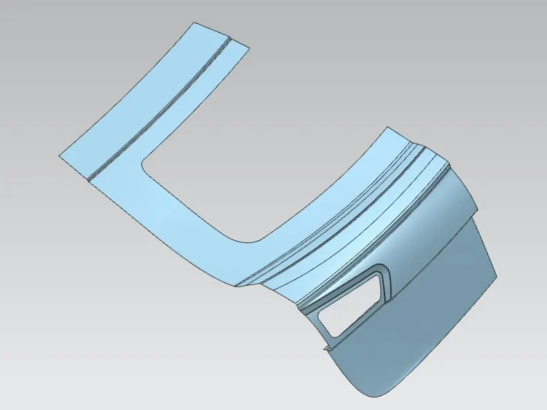
- Then after, create the tooling direction.It is the direction where the inner panel can be deep drawned during manufacturing in given tooling direction.
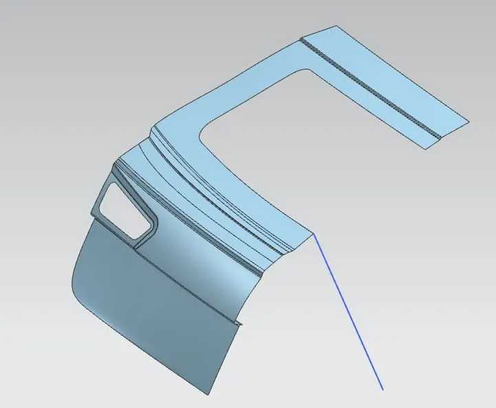
- After creating the tooling direction, firstly create the sealing flange.This flanged portion of back door presses a rubber strip of back body outer which acts as sealant between back door and luggage area in order to avoid any water obstacles to inside.
- So for that, I have offset the working surfaces to required distances and trim the unwanted portion using trim sheet and then generate the required studio surfaces guided by some bridge curves.
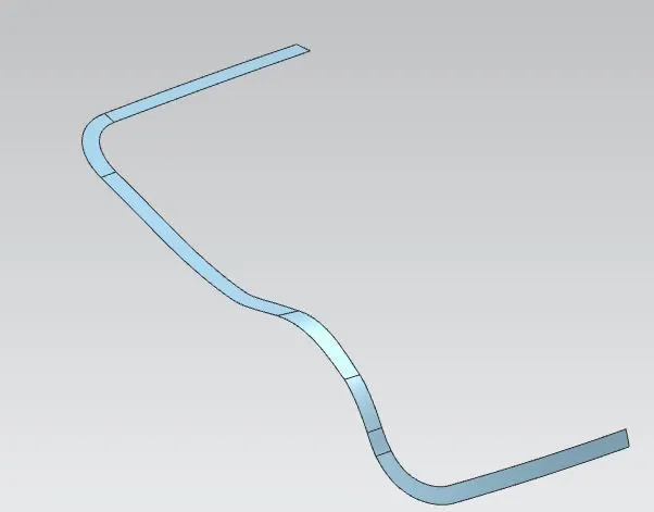
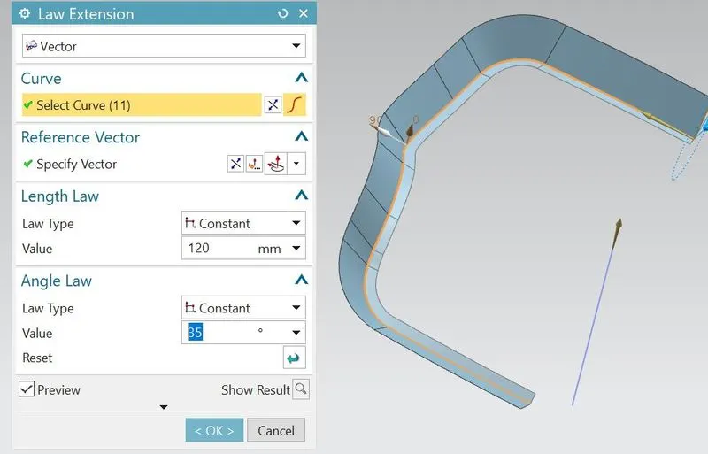
- Using law extension, develop the flange connecting to sealing flange.
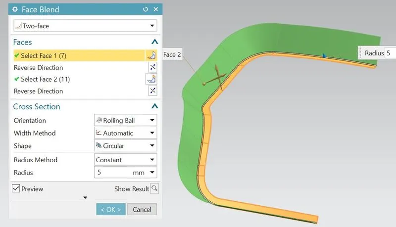
- Using face blend, create the blend between two flange faces.So then the connecting flange can be completed.
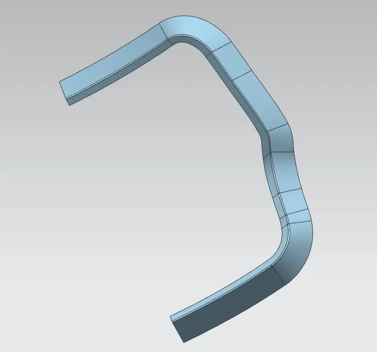
- Using the working surfaces and connected flange, develop the connecting blends by using trim and extend feature.
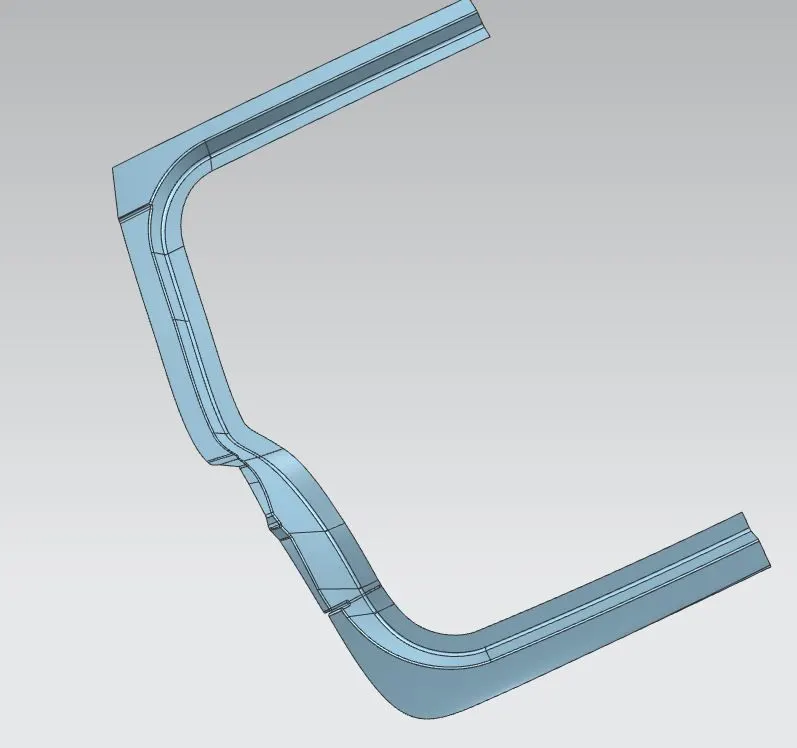
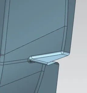
- Using law extension feature, Create the inner connecting flange connected with sealing flange.
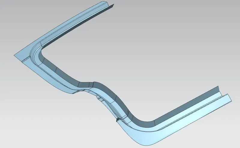
- Again using working surfaces & trim and extend feature, create the windshield area and bottom area of inner panel
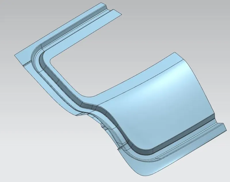
- Then after, I have created embosses on the inner panel for to increase the strength of panel and also remove some material to reduce the weight of part.The embosses are created with respect to the tooling direction in order to easily dissipated the forces towards outwards.
-
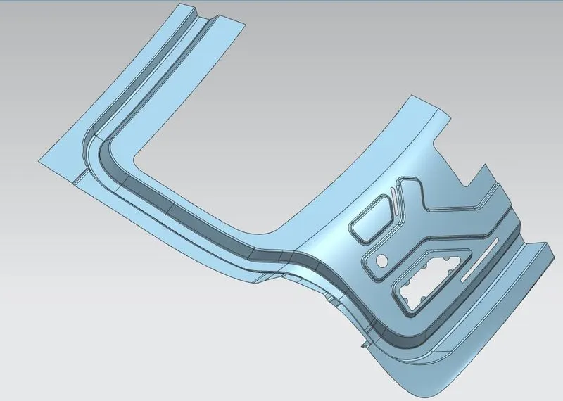
- Then after, a mastic flange can be created.This the flange of inner panel is attached to outer panel by the application of mastic sealant.Although the inner panel and outer panel is connected by hemming process at ends but this mastic flange helps to get connected at the centre portions.The gap between mastic flange and outer panel will be 5mm.So that only we can apply the mastic sealant between them.Each mastic sealant can cover 80mm area in diameter.
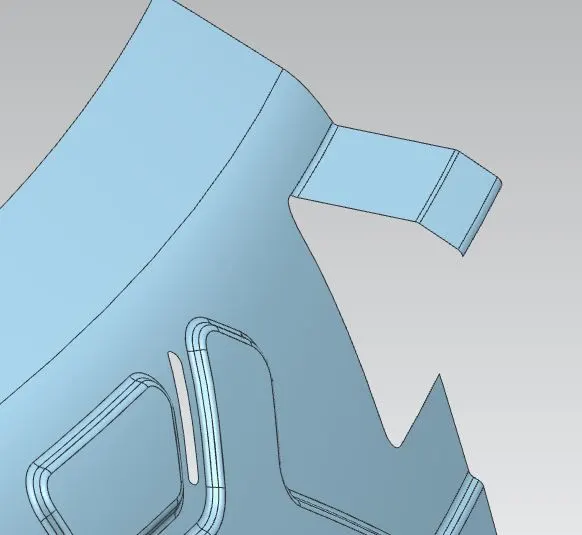
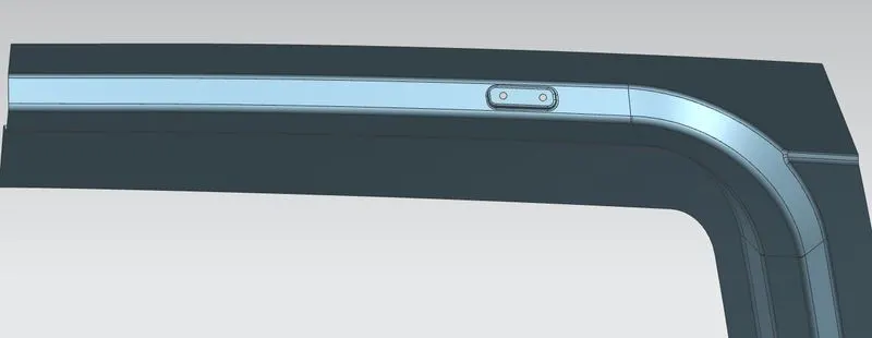
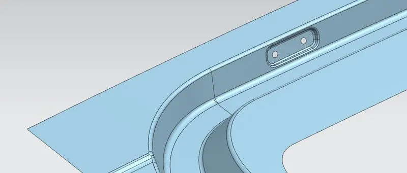
- Then after, I have created the flat emboss for mounting of hinge to the inner panel.The flat emboss must be maintain because it can increase the tightness between hinge and inner panel.Also maintain minimum 5mm space away from mounting holes for fasteners.Finally add the required blends to the hinge emboss.
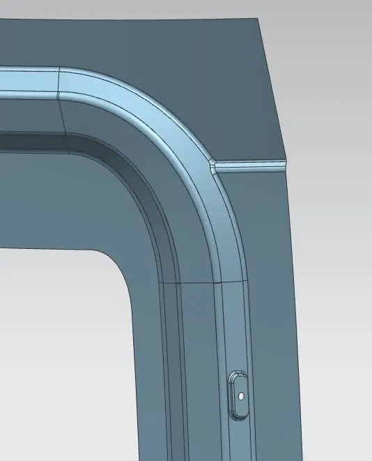
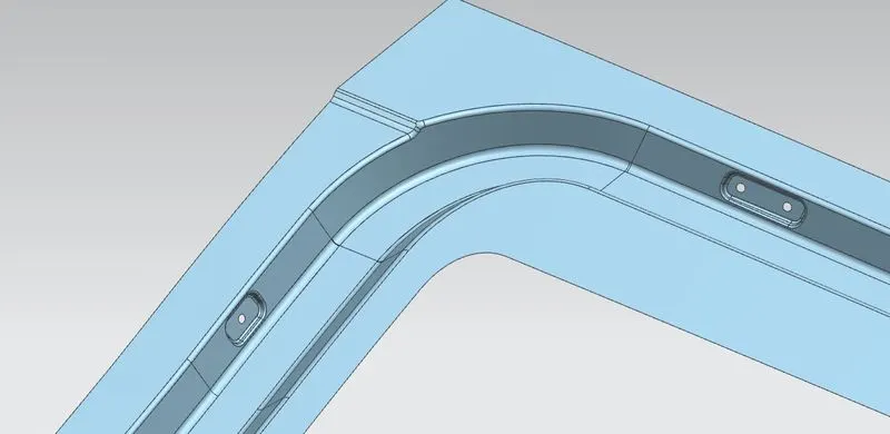
- Similarly, I have created the flat emboss for mounting of gas stay.The angle between hinge mounting and gas stay mounting must lie only in between 80 deg to 90 degrees.
- So half of the inner panel is completed.Mirror it along XY plane to get complete panel and sew them together.
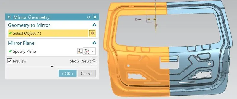
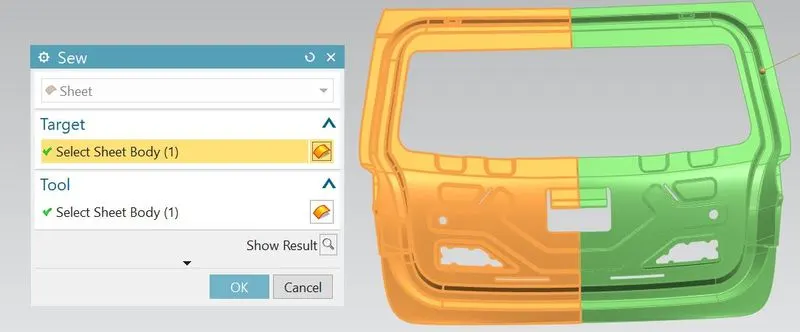
- For creating srtiker mounting region and for proper opening and closing of door,the striker should be positioned properly(perpendicular to trajectory of hinge axis).Here,I dont have any striker or hinges.So for that, I have drawn axis line betwen two hinge mountings.After that, a trajectory circle is drawn from centre of axis as it crosses the surface where the striker to be positioned.So then draw the line tagent to trajectory circle.The point where the tangent line and trajectory circle meets is the striker position.
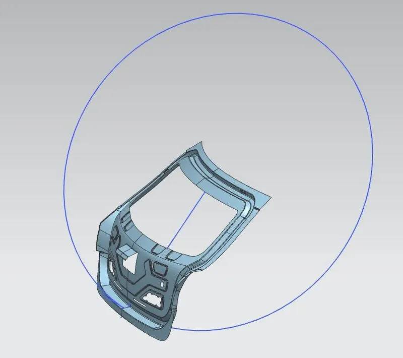
- So at that particular position, I have created the striker mounting area with flat emboss.
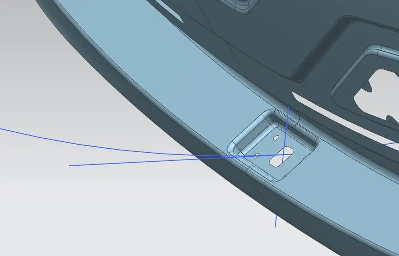
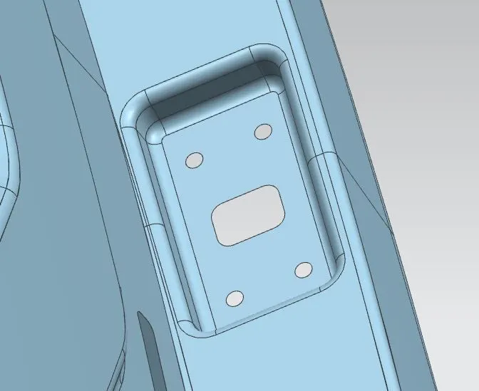
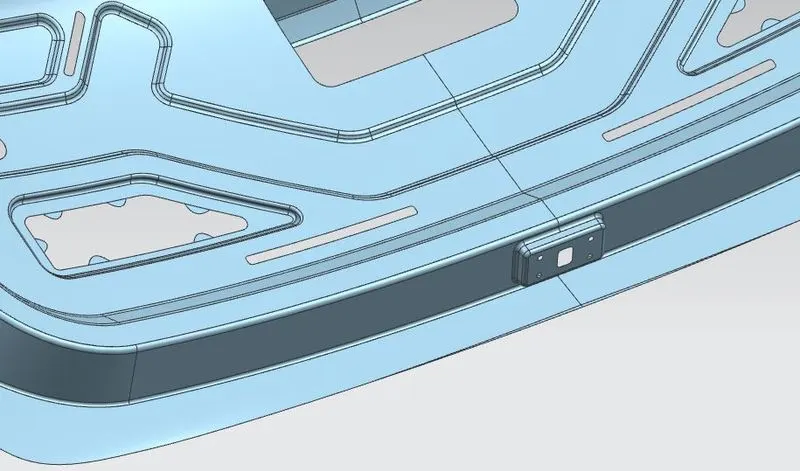
- After that, I have created the flat emboss for wiper mounting near the windshield glass area as shown.
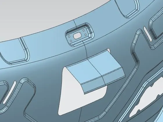
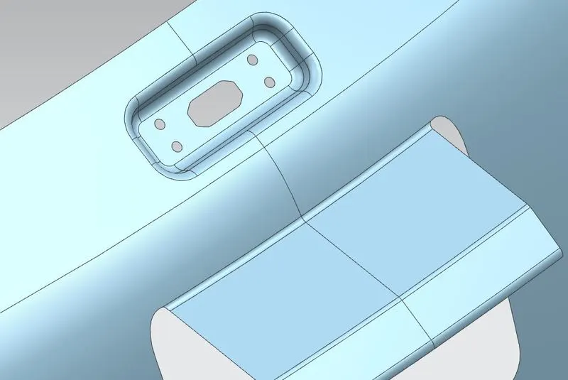
- Using the thicken feature, thicken the surface to 0.75mm and hide the sheet surface.So that thicken part can clearly visible.
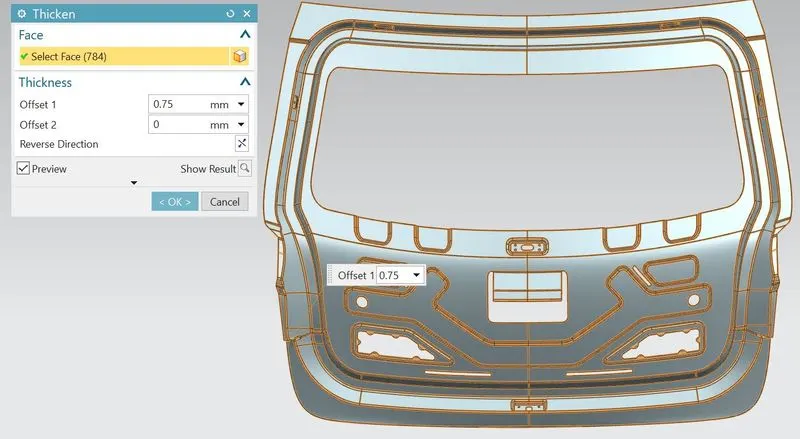
- So that inner panel should be completed.
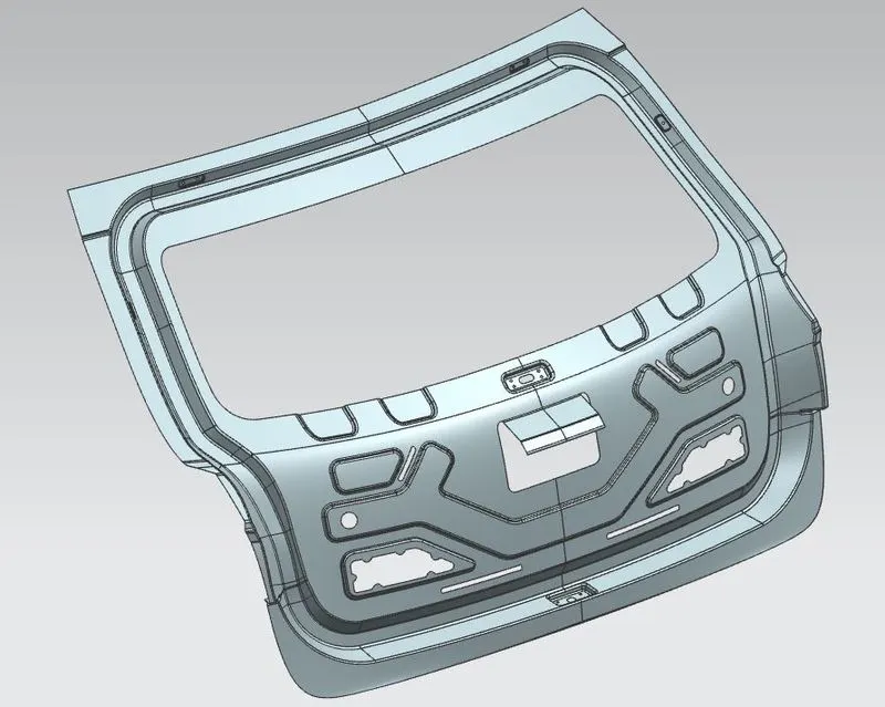
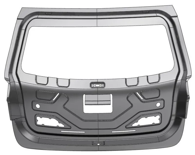
- For hinge reinforcement, create the new part in the assembly and name it as Hinge-Reinforcement-LH.
- Go to hinge reinforcemet part navigator, copy the required surfaces using the wave geometry linker.
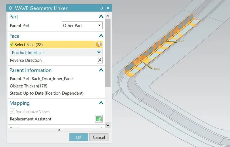
- Trim the excess sheet as per the requirement of reinforcement.
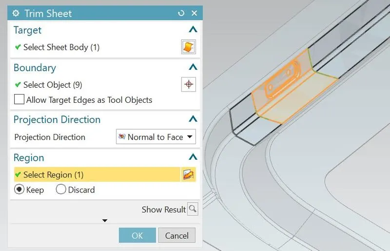
- Generate bridge curves on corners and trim the excess portion for to avoid sharp corners or edges.
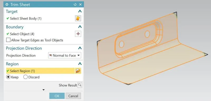
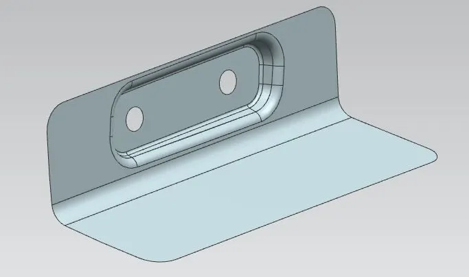
- Thicken the sheet to 1.5mm
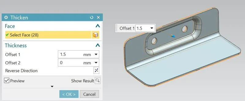
- So that hinge reinforcement on LH side should be completed.
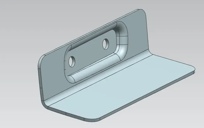
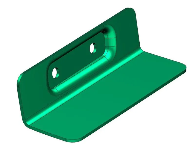
- Using mirror assembly feature, mirror the LH side reinforcement with respect to XY plane to get in on the Right hand(RH) side.
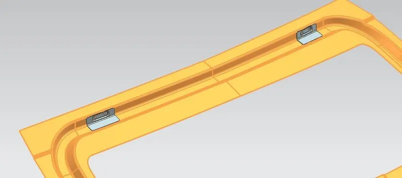
- For gas stay reinforcement, create the new part in the assembly and name it as Gas-stay-Reinforcement-LH.
- Go to gas stay reinforcemet part navigator, copy the required surfaces using the wave geometry linker.
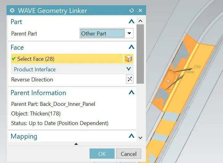
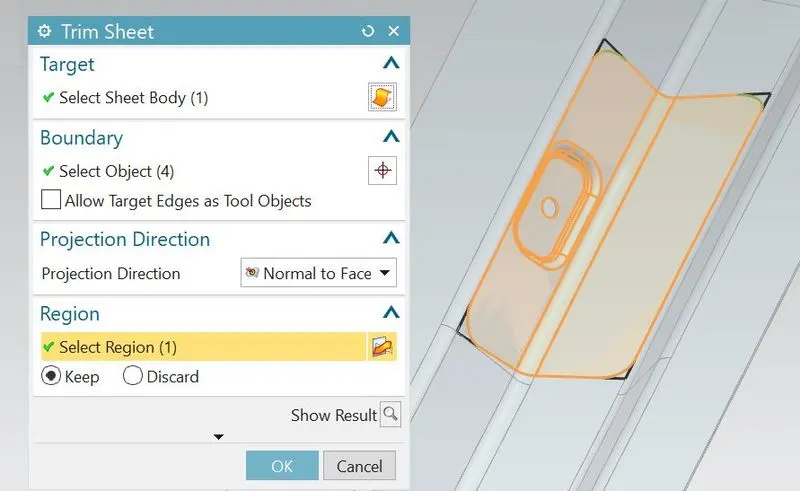
- Trim the excess sheet as per the requirement of reinforcement.
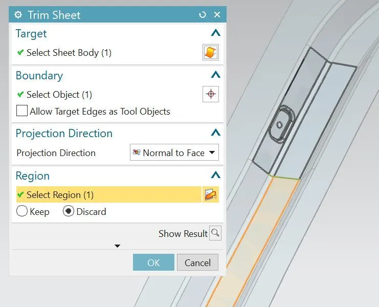
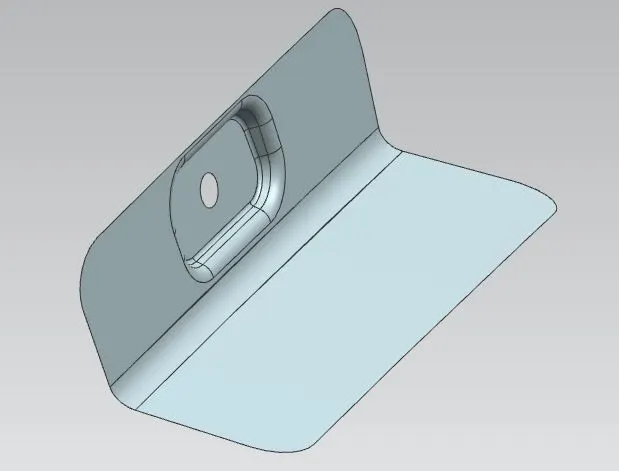
- Generate bridge curves on corners and trim the excess portion for to avoid sharp corners or edges.
- Thicken the sheet to 1.5mm
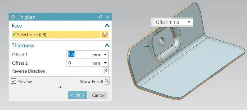
- So that Gas stay reinforcement on LH side should be completed.
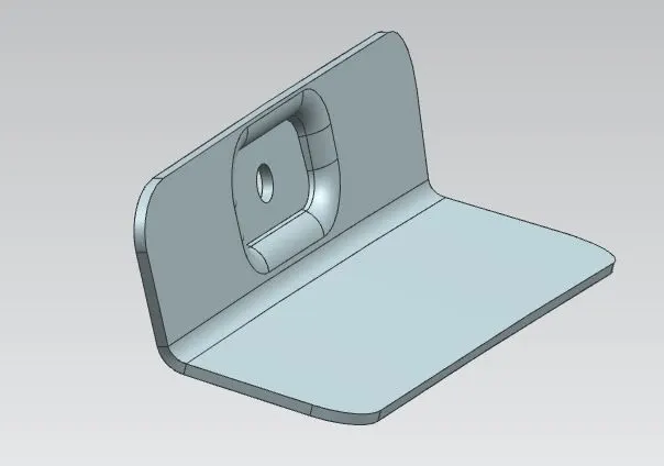
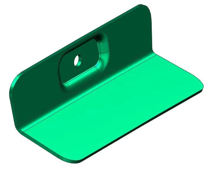
- Using mirror assembly feature, mirror the LH side reinforcement with respect to XY plane to get in on the Right hand(RH) side.
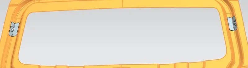
- For wiper mounting reinforcement, create the new part in the assembly and name it as Wiper-Reinforcement.
- Go to wiper reinforcemet part navigator, copy the required surfaces using the wave geometry linker.
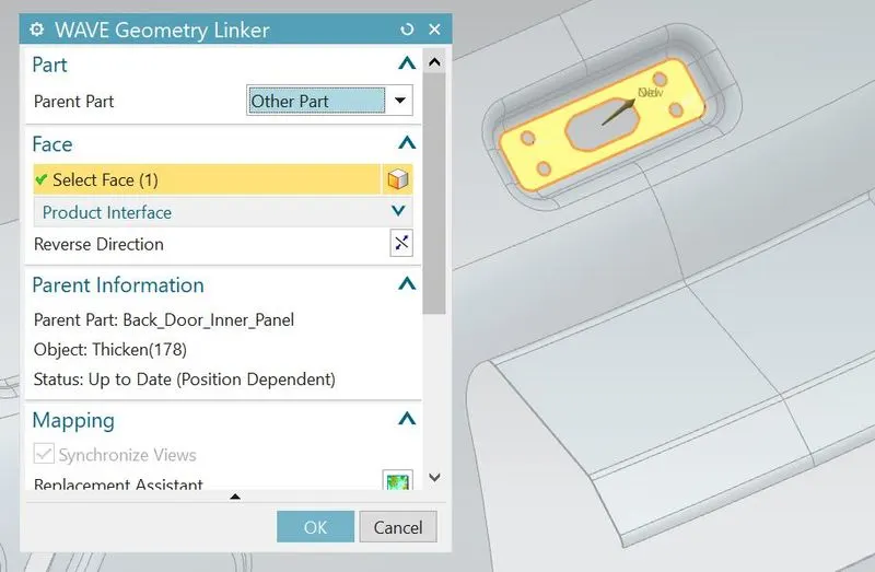
- Thicken the sheet to 1.5mm
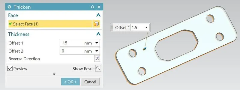
- So that wiper mountig reinforcement should be completed.
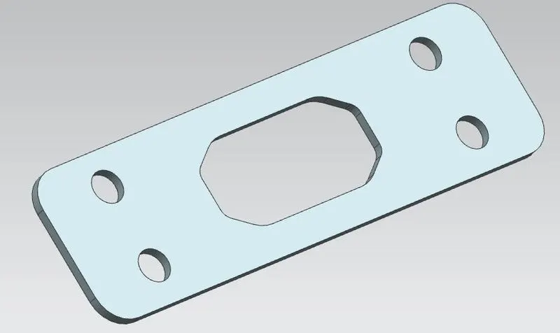
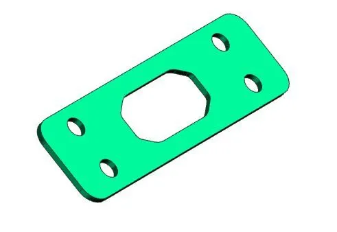
- For striker mounting reinforcement, create the new part in the assembly and name it as striker-Reinforcement.
- Go to striker reinforcemet part navigator, copy the required surfaces using the wave geometry linker.
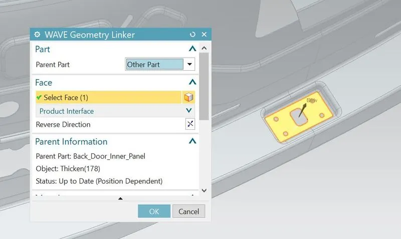
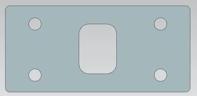
- Thicken the sheet to 1.5mm
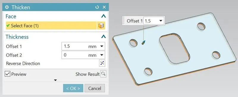
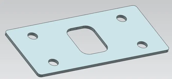
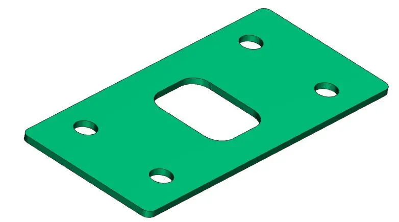
- So that striker mountig reinforcement should be completed.
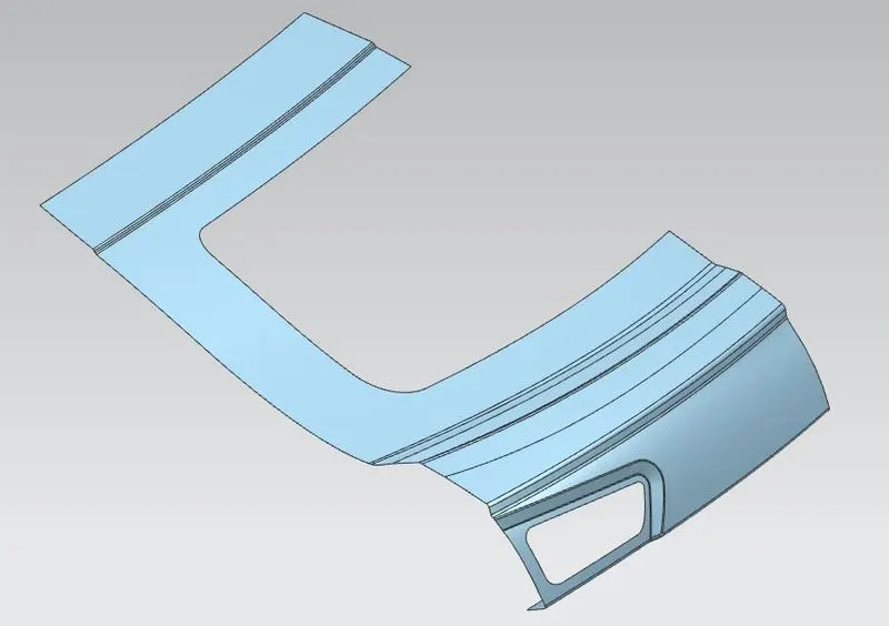
- Go to upper outer panel part navigator and extract the working surface from styling surface.
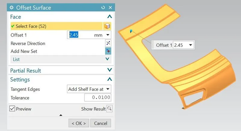
- Offset the working surface to 2.45 mm.
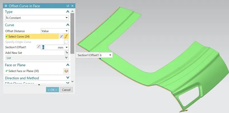
- On offset surface,offset the curve to 6mm for to create the hemming flange.
- Trim the offset surface excluding 6mm offset curve space.
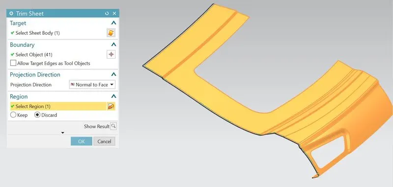
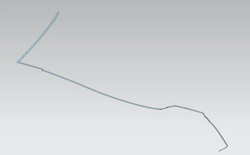
- So there are two flanges-one is upper flange and another one is 6mm lower flange.
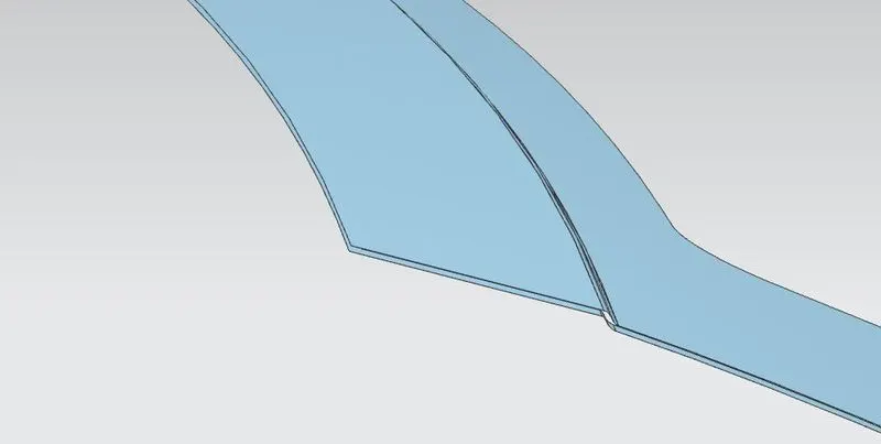
- Then after bridge the curves in between two flanges and developed the hemming by using swept, studio surface or through curves mesh features.
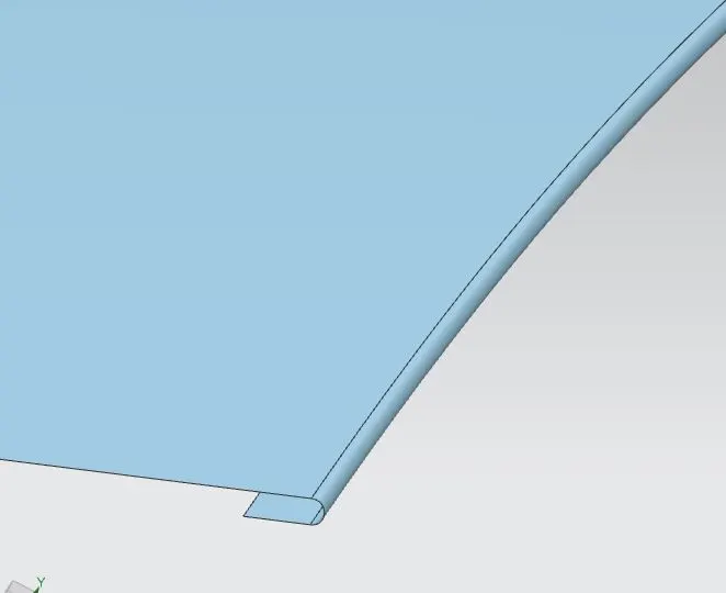
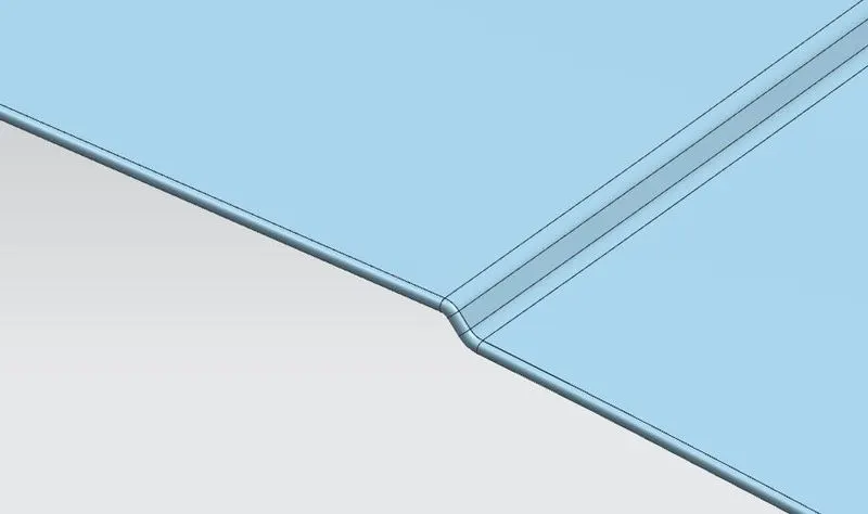
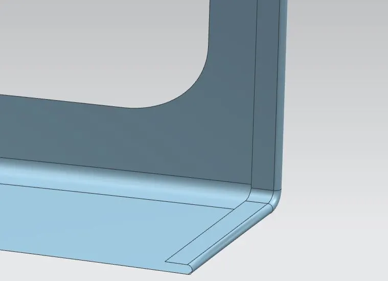
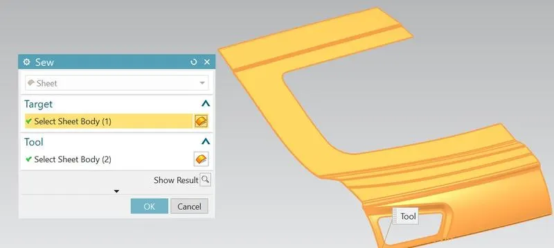
- Then after sew them all together.
- For giving relief at the corners, draw the relief curve using spline feature and trim the excess portion.
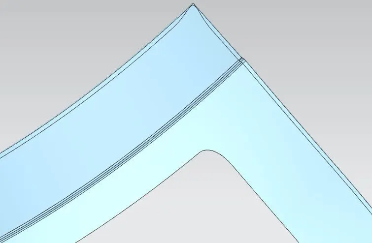
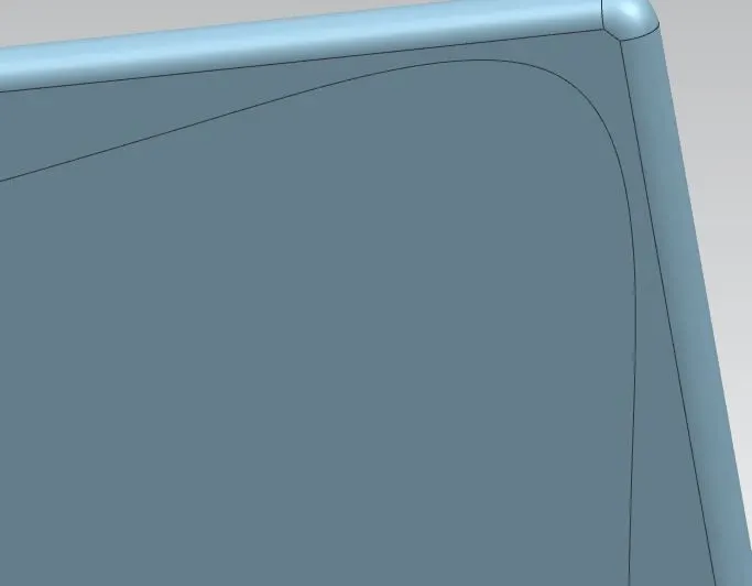
- Mirror the panel along XY plane and sew them together.
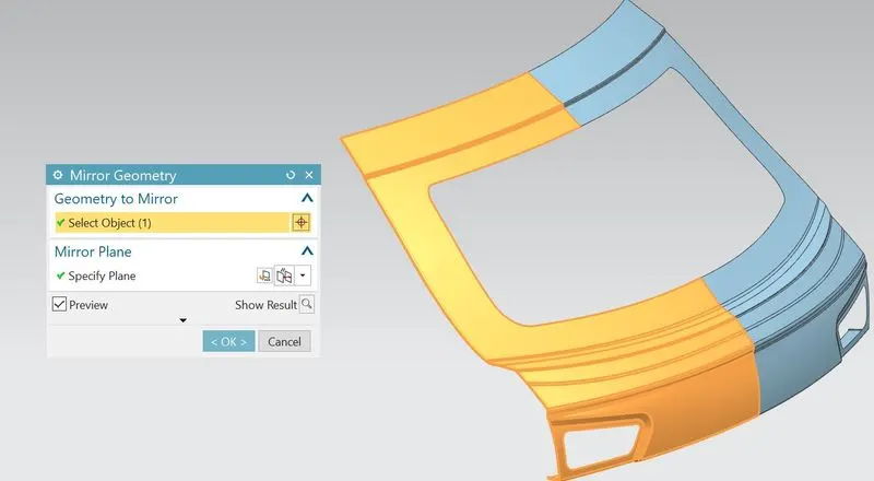
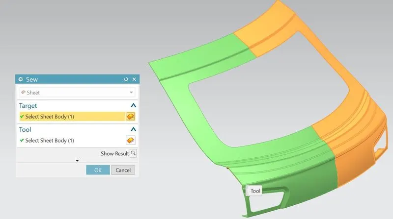
- Thicken the part inside to about 0.75mm.
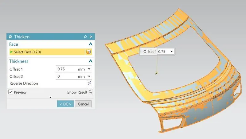
- So the Upper outer panel should be completed.
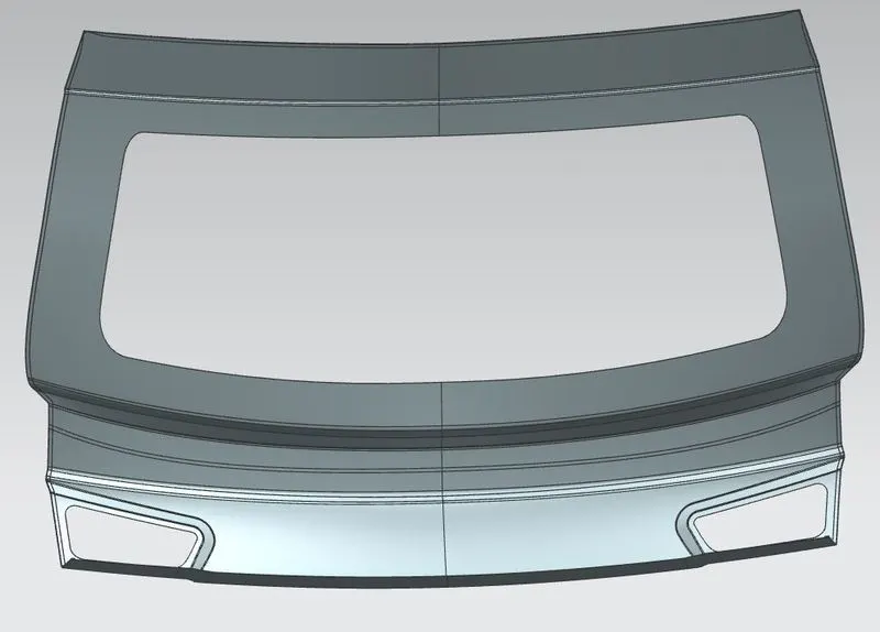
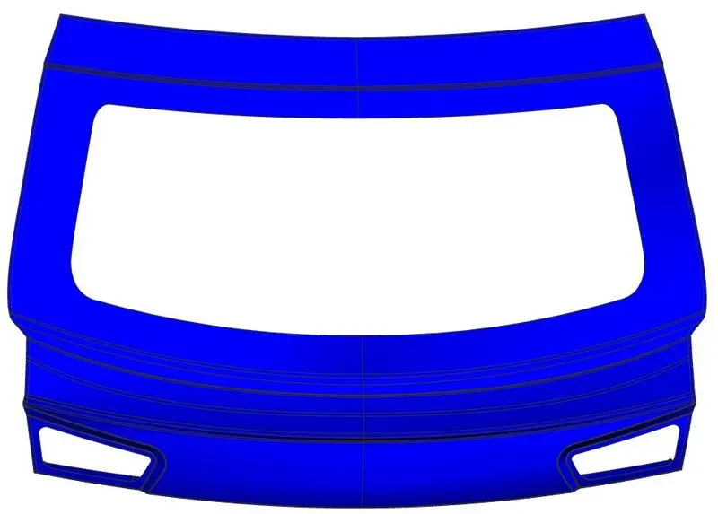
- Go to Lower outer panel part navigator and extract the working surface from styling surface.
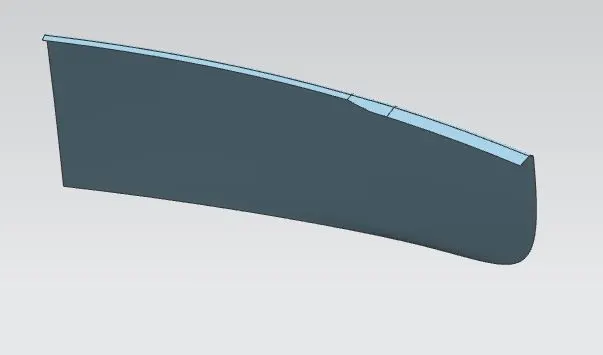
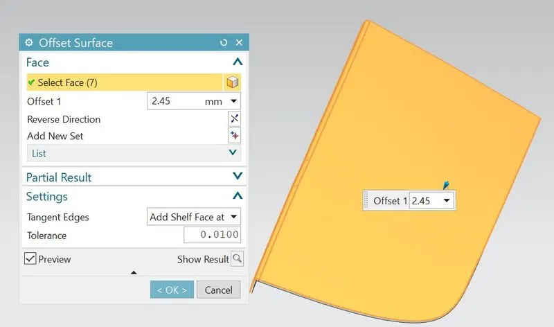
- Offset the working surface to 2.45 mm.
- On offset surface,offset the curve to 6mm for to create the hemming flange.
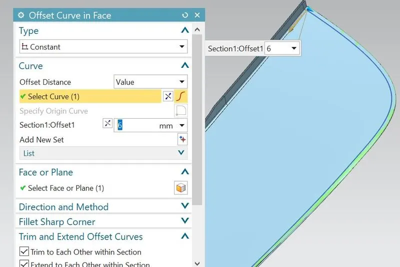
- Trim the offset surface excluding 6mm offset curve space.
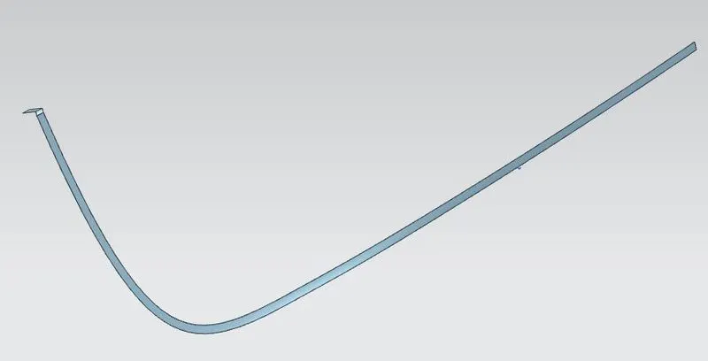
- So there are two flanges-one is upper flange and another one is 6mm lower flange.
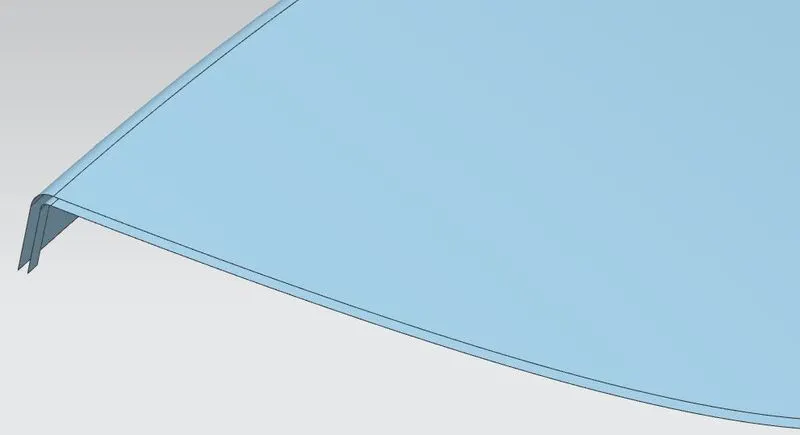
- Then after bridge the curves in between two flanges and developed the hemming by using swept, studio surface or through curves mesh features.
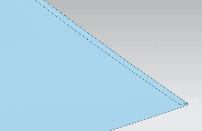
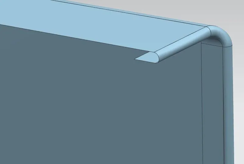
- Then after sew them all together.
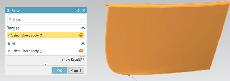
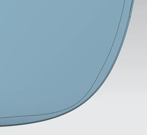
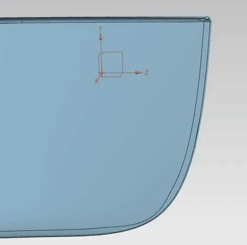
- For giving relief at the corners, draw the relief curve using spline feature and trim the excess portion.
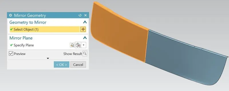
- Mirror the panel along XY plane and sew them together.
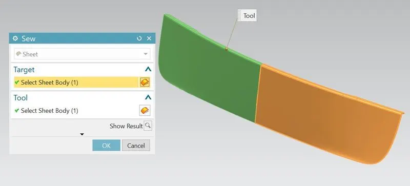
- Thicken the part inside to about 0.75mm.
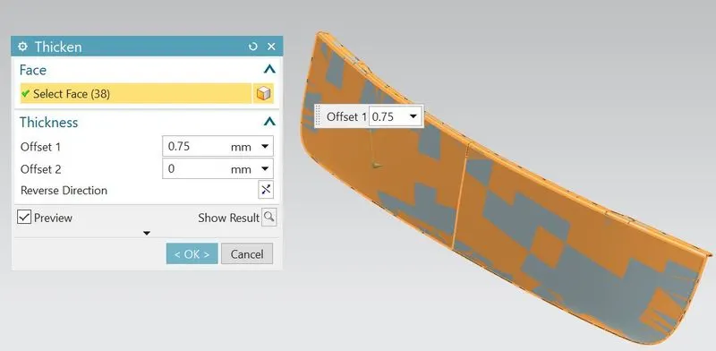
- So the Lower outer panel should be completed.
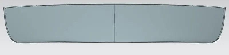
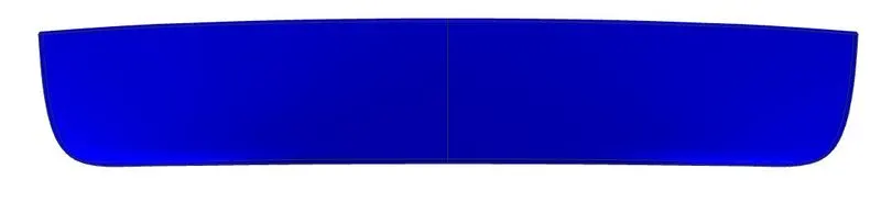
- Hence all the components of back door can be completed and assembled.After that, I have checked the various positions of back door i.e;satisfying as per manufacturing requirements or not.
Hemming section view
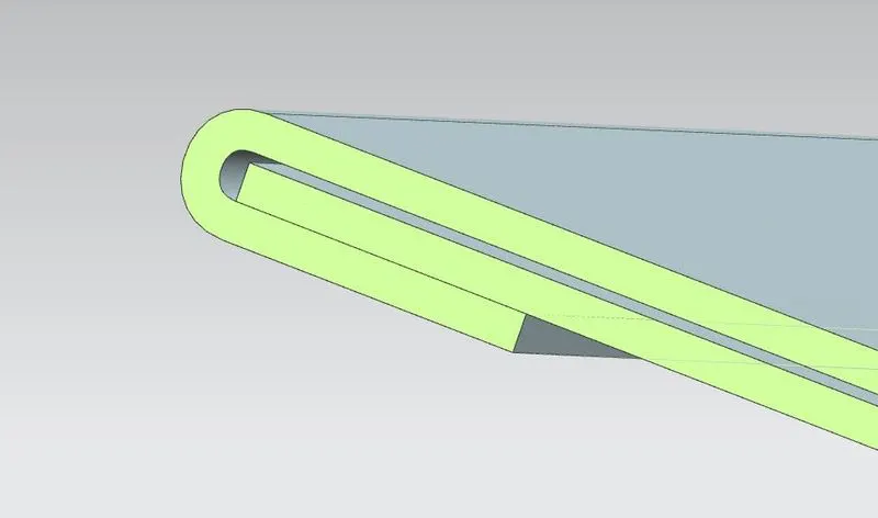
Position of upper and lower outer panel hemming flanges with respect to inner panel
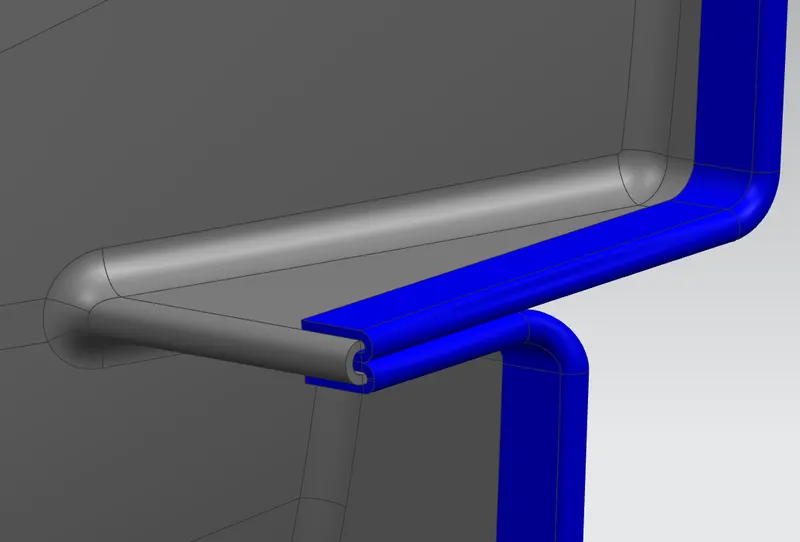
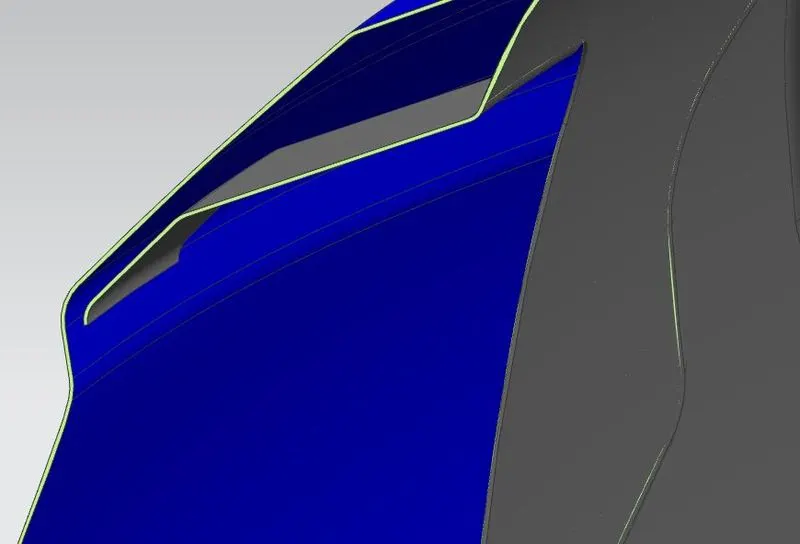
Corner reliefs on upper and lower outer panels
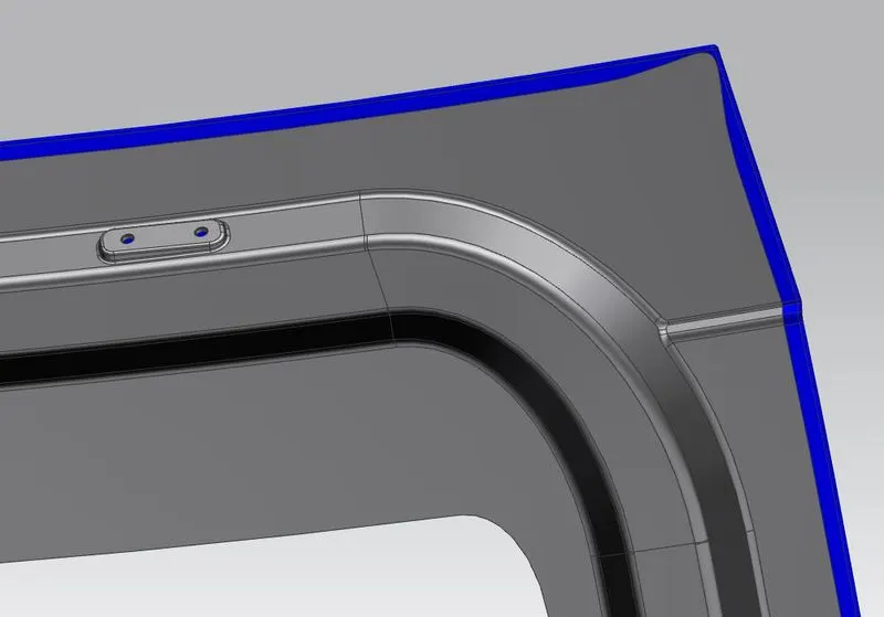
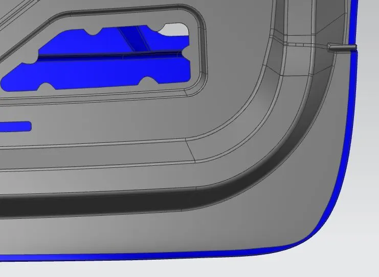
Mastic sealant area(Maintained 5mm gap between inner and outer panel)
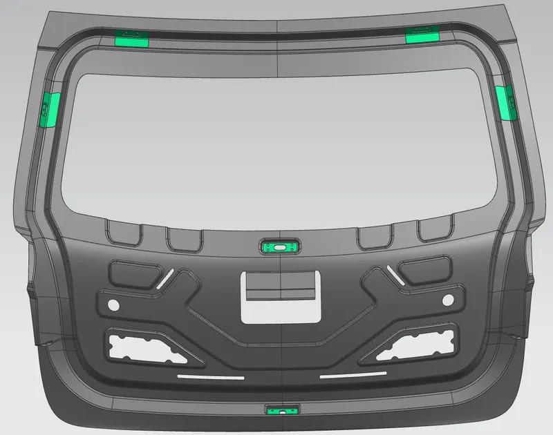
Reinforcements assembly positions on inner panel
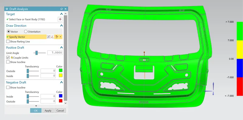
Draft Analysis:
Draft analysis is a tool to check the correct application of draft to the faces of their part and verifies the draft angles or examine angle changes within a face.It commonly detect whether the designed component within the positive draft or negative draft.Positive draft means the angle of face with respect to the direction of pull is more than reference angle.Negative draft means the angle of face with respect to the direction of pull is less than the reference angle.
In the NX software, the draft analysis tool represents draft result with colour zones.The minimum draft angle of steel is 7° and it is considered as positive draft in the analysis which represents as green colour.If the draft angle is less than 7°,it identifies the component having negative draft and can represent in yellow, Blue and red colours.
Conclusion:
Design and assembly of back door(BIW) along with its reinforcements can be successfully designed as per the manufacturing requirements and functional requirements by using NX-CAD software and also got a advanced knowledge on surface tools or commands.