Design of backdoor
Back Door:
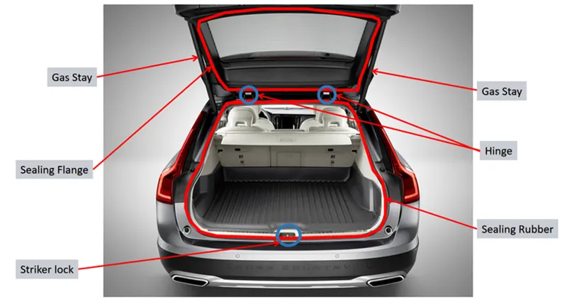
Backdoor or Tailgate is the hinged door at the rear part of a vehicle and can be moved up or down. It lets us access the boot
space or trunk.
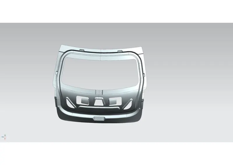
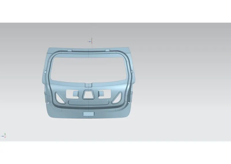
Parts of Back door assemble –
- Inner Panel
- Outer Panel
- Hinge Mounting Bracket
- Hinge Inner Reinforcement
- Latch Inner Reinforcement
- Wiper Motor Mounting Bracket
- Gas Stay mountings and reinforcement(Heaver back doors)
The trunk or boot of a car is the vehicle's main storage or cargo compartment, often a hatch at the rear of the vehicle. It is also called a tailgate.
Back doors are designed depends upon the hinge assembly and gas stay.
1.Hinges inside the back door.
The hinges are placed under the back door of the car.
In this model,there are two variants depends upon the gas stay of the back door
1.Gas stay is mounted on the back door
2.Gas stay is fixed on the back of the BIW
2.Hinges outside the back door:
The hinges are placed outside of the back door and it is protected by plastic parts.
In this model,there are two variants depends upon the gas stay of the back door
1.Gas stay is mounted on the back door
2.Gas stay is fixed on the back of the BIW
Outer panel is hemmed with Inner panel through Hemming process.
Hemming:
Hemming is a forming operation in which the edges of the sheet are folded or folded over another part in order to achieve a tight fit. Normally hemming operations are used to connect parts together, to improve the appearance of a part and to reinforce part edges.
In car part production, hemming is used in assembly as a secondary operation after deep drawing, trimming and flanging operations to join two sheet metal parts (outer and inner) together. Typical parts for this type of assembly are hoods, doors, trunk lids and fenders.
The accuracy of the hemming operation is very important since it affects the appearance of the surface and surface quality. Material deformations, which occur during the hemming process, can lead to dimensional variations and other defects in parts. Typical hemming defects are splits or wrinkles in the flange, material overlaps in the corner areas or material roll-in.
Conventional die hemming
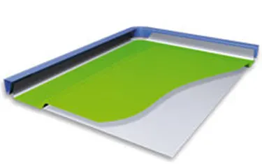
Conventional die hemming is suitable for mass production. In die hemming, the flange is folded over the entire length with a hemming tool. Normally the actual hemming is a result of a forming operation in which the flange is formed with a hemming tool after the drawing and trimming operations have been completed. The formed flange is then hemmed in several process steps. These steps include, for example, the pre-hemming and final hemming depending on the respective opening angle of the flange. Production plants for conventional die hemming are very expensive, but the cycle times are very low.
Roll hemming
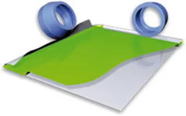
Roll hemming is carried out incrementally with a hemming roller. An industrial robot guides the hemming roller and forms the flange. Roll hemming operation can also be divided into several pre-hemming and final hemming process steps. Roll hemming is very flexible to use and tool costs are significantly lower as compared to those of conventional die hemming. However, the cycle times are much higher since the hemming is realized using a hemming roller which follows a defined path.
Manufacturing Process:
Deep Drawing Process:
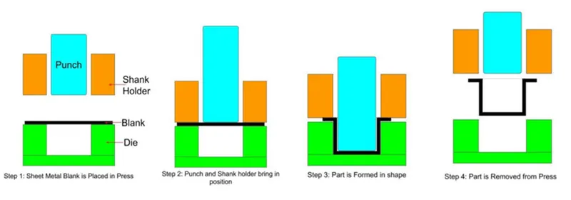
Deep drawing is a sheet metal forming process in which a sheet metal blank is radially drawn into a forming die by the mechanical action of a punch. It is thus a shape transformation process with material retention. The process is considered "deep" drawing when the depth of the drawn part exceeds its diameter. This is achieved by redrawing the part through a series of dies. The flange region (sheet metal in the die shoulder area) experiences a radial drawing stress and a tangential compressive stress due to the material retention property.
These compressive stresses (hoop stresses) result in flange wrinkles (wrinkles of the first order). Wrinkles can be prevented by using a blank holder, the function of which is to facilitate controlled material flow into the die radius.
Deep drawing is always accompanied by other forming techniques within the press. These other forming methods include:
- Beading: Material is displaced to create a larger, or smaller, diameter ring of material beyond the original body diameter of a part, often used to create O-ring seats.
- Bottom Piercing: A round or shaped portion of metal is cut from the drawn part.
- Bulging: In the bulging process a portion of the part's diameter is forced to protrude from the surrounding geometry.
- Coining: Material is displaced to form specific shapes in the part. Typically coining should not exceed a depth of 30% of the material thickness.
- Curling: Metal is rolled under a curling die to create a rolled edge.
- Extruding: After a pilot hole is pierced, a larger diameter punch is pushed through, causing the metal to expand and grow in length.
- Ironing / Wall Thinning: Ironing is a process to reduce the wall thickness of parts. Typically ironing should not exceed a depth of 30% of the material thickness.
- Necking: A portion of the part is reduced in diameter to less than the major diameter.
- Notching: A notch is cut into the open end of the part. This notch can be round, square, or shaped.
- Rib Forming: Rib forming involves creating an inward or outward protruding rib during the drawing process.
- Side Piercing: Holes are pierced in the side wall of the drawn part. The holes may be round or shaped according to specifications.
- Stamping / Marking: This process is typically used to put identification on a part, such as a part number or supplier identification.
Incremental Deep Drawing:
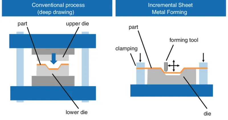
Incremental deep drawing or Incremental sheet forming (or ISF, also known as Single Point Forming) is a sheet metal forming technique where a sheet is formed into the final workpiece by a series of small incremental deformations. However, studies have shown that it can be applied to polymer and composite sheets too. Generally, the sheet is formed by a round tipped tool, typically 5 to 20mm in diameter. The tool, which can be attached to a CNC machine, a robot arm or similar, indents into the sheet by about 1 mm and follows a contour for the desired part. It then indents further and draws the next contour for the part into the sheet and continues to do this until the full part is formed. ISF can be divided into variants depending on the number of contact points between tool, sheet and die (in case there is any). The term Single Point Incremental Forming (SPIF) is used when the opposite side of the sheet is supported by a faceplate and Two Point Incremental Forming (TPIF) when a full or partial die supports the sheet. The ISF process is generally implemented by clamping a sheet in the XY plane, which is free to move along the Z axis. The tool moves in the XY plane and is coordinated with movements in the Z axis to create the desired part. It is often convenient to retrofit a CNC milling machine to accommodate the process. Spherical, flat-bottomed, and parabolic tool profiles can be used to achieve differing surface finishes and forming limits
Spot Welding:
Spot welding is a resistance welding process that joins metals together by applying pressure while supplying electric current to the weld area. It was first introduced in 1885 when Elihu Thomson accidentally fused two copper wires together in an experiment.
Spot welding has become a staple welding process in manufacturing and assembly, especially in the sheet metal fabrication sector and automotive industry. Suitability for automation plays a big part in its rise in popularity as robotic spot welding excels at speed and efficiency.
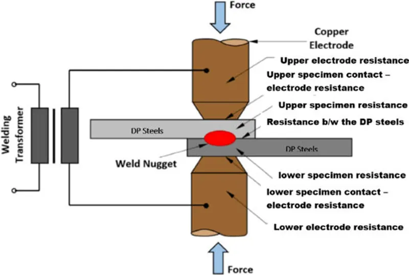
Spot welding (RSW) is an electrical resistance welding process that joins overlapping metals between two electrodes. Pressure is applied by squeezing the workpieces between the electrodes and heat is generated by the passage of welding current through the resistive metals. This allows the materials to fuse and create a welding joint. The joint created through resistance spot welding resembles a button or a nugget, thus the term spot welding was coined as the current is applied precisely over a small area on the metal’s surface.
As the metals are fused using large amounts of energy in a short period (approximately 10-100 milliseconds), the area around the weld nugget stays unharmed by the excessive heat, thus the heat-affected zone is minimal and a clean weld is created.
The amount of heat generated in spot welding is expressed by the heat-energy formula:
Q = I2Rt
Where Q is the heat energy, I is the current, R represents the electrical resistance and t is the time or duration in which the current is applied.
Spot Welding Process
The spot welding process works through the delivery of low voltage, high-current electrical pulses to the weld electrodes in order to almost instantaneously melt the metal while applying enough pressure for the metals to fuse. The process resembles the cold welding process in terms of applying pressure, but in cold welding, no electrical current is supplied to the weld.
The first stage in spot welding is to place the overlapping metal sheets or workpieces. After the metals are firmly set in place, the application of pressure through the electrode force is performed. This pressure may be applied manually, pneumatically, by springs or through hydraulics, depending on the machine type.
The second stage involves the application of heavy current to the targeted area between the electrodes. Molten metal forms as the current reacts with the metal’s internal resistance. The metals reach about 2000 °C, which is above their fusion point. The electrodes must have a higher melting point than the workpieces. Generally, copper alloy electrodes are used but depending on the welded metal, the electrodes can also be made from tungsten, molybdenum and other materials.
The final stage involves the cooling and solidification of the nugget. In this stage, the welding electrodes remain in contact with the nugget and act as support as the metals cool down and harden. The process is finished once the metals have cooled down.
b
There are quite a few variables to check and adjust during the welding cycle in order to create a weld with satisfactory quality:
- Pressure
Applying the correct amount of pressure or electrode force is paramount in creating quality welds. The joint will be too small and weak if the applied pressure is inadequate. On the other hand, too much pressure might cause cracking in the spot weld, as the molten metal can cause thinning of the sheets. It is advised that the electrode’s depth of depression should never exceed 25% of the sheet’s thickness.
- Current
The amount of heat generated depends on the electrical resistance and thermal conductivity of the metal. The classification of the metal should be considered when determining the amount of current for the machine.
- Tip diameter
The welding tip diameter controls the size of the spot weld. If the tip is too small, the weld nugget can be too small and weak, whereas a tip that is too large can cause overheating of the metals and the development of voids and gas pockets.
- Welding time cycle
Spot weld results can be improved and imperfections avoided by adjusting the time that the metals are subjected to electrode pressure and weld current.
- Squeeze time refers to the period when the welding tip of the electrode applies pressure to the overlapping metals.
- Upslope is the time in which the electric current reaches its peak value.
- Weld time is the duration wherein the electric current flows between the electrodes. During this time, heat is generated and fusion takes place between the metals.
- Downslope is the span where the electric current is cut out from its peak value.
- Hold time refers to the resting period where the molten metal solidifies. Electrode pressure is still applied during this period and the electrodes conduct heat away from the weld.
- Off time is used to signify the current’s delay from the end of the sequence to the start of the next one.
Applications of Spot Welding
Automotive Industry
Spot welding is a key element in the automotive industry since manufacturing car parts using this method is cost-efficient, reliable and fast. Companies automate assembly lines by using spot welding robots. A metal sheet made from steel or aluminum alloy can easily be transformed into a functional assembly part in seconds, all this with exceptional precision and repeatability.
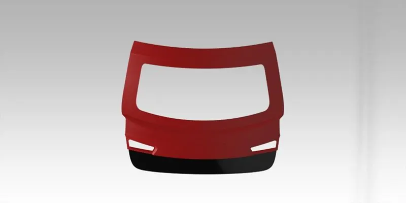
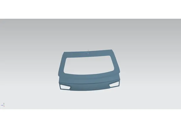
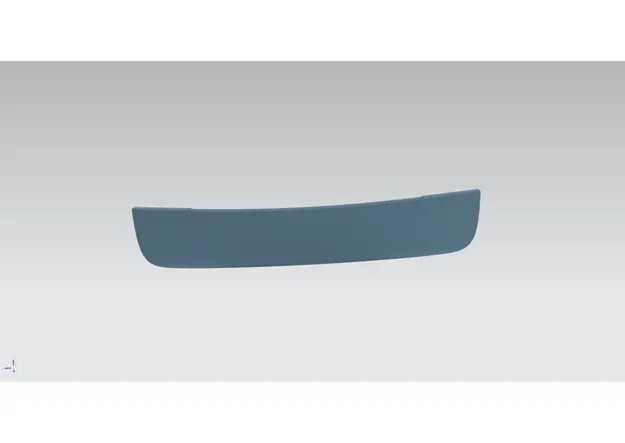
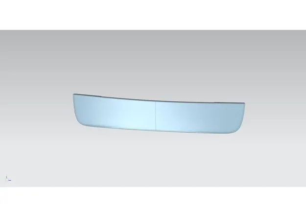
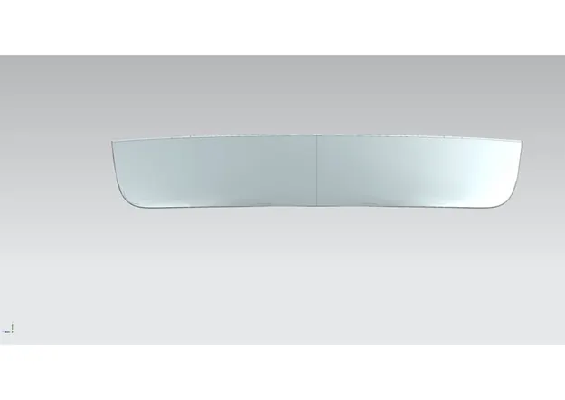
Outer Panel has two parts upper and lower
Back door - Upper:
Back door upper has rear windshield glass ,wiper mountings,Tail light mountings
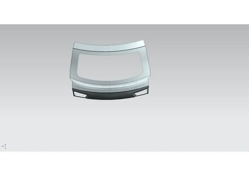
Back door - Lower:
Back door lower is spot welded with upper.
It has latch opening mechanisms.
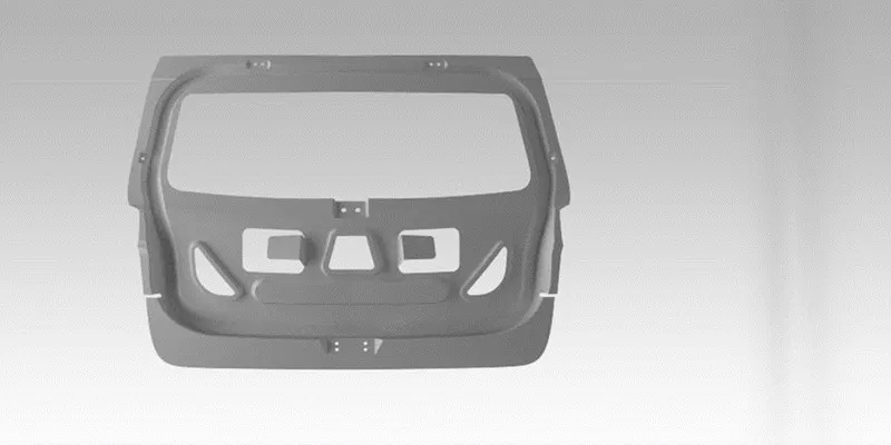
Back door Inner panel:
Back door Inner panel is hemmed with back door Outer panel Upper and lower.
Back door inner panel is welded with hinge reinforcements,gas stay reinforcements,wiper motor reinforcements and Latch reinforcements.
Reinforcements are given to back door inner panel because hinge areas,gas stay, wiper motor areas has low strengths.To strength those areas ,reinforcements are given to strengthen those areas.
Hinge areas:
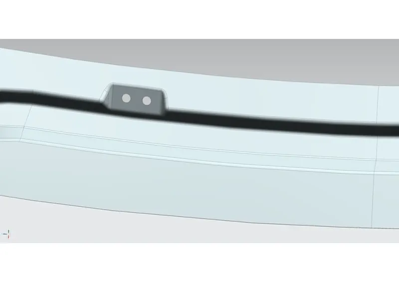
Gas stay areas:
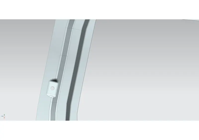
Wiper Motor areas:
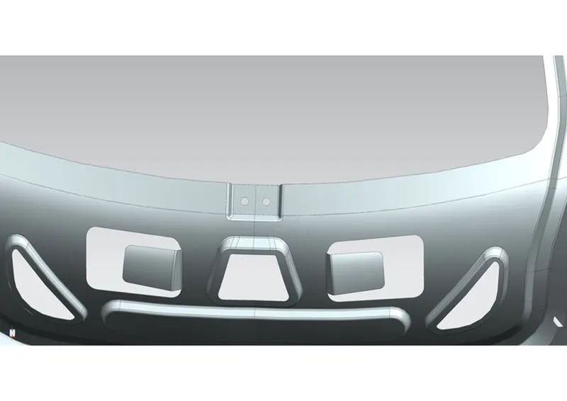
Latch areas:
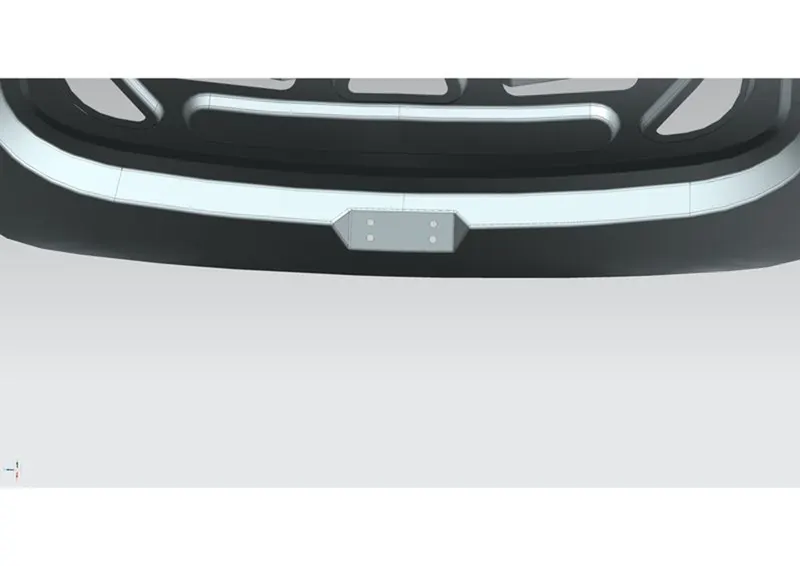
Reinforcements:
Hinge reinforcements
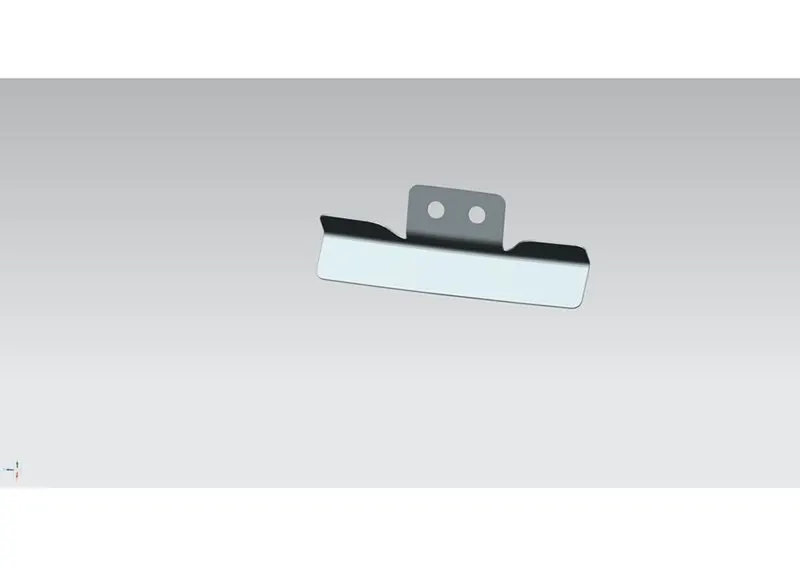
Gas Stay reinforcements
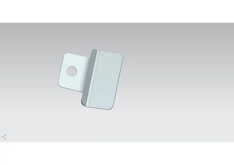
Wiper Motor reinforcements:
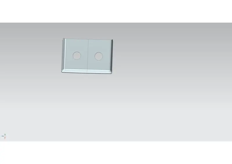
Latch Reinforcements
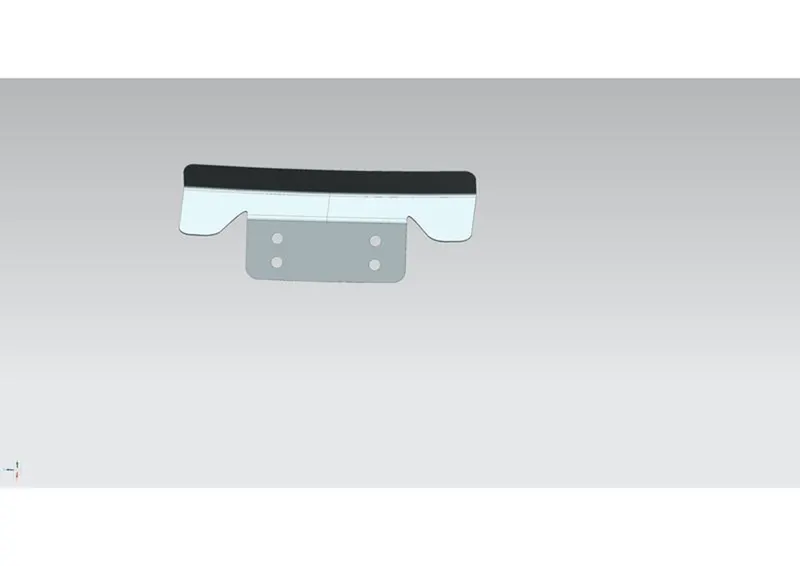
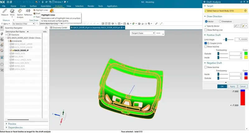
Draft Analysis