Design of backdoor
- BACK DOOR DESIGN :
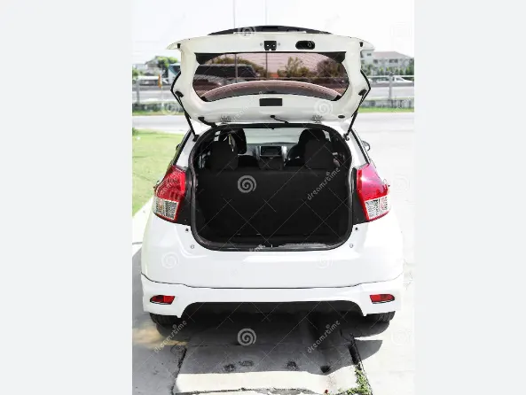
Backdoor are one of the type of door of the vehicle which are located next to the passanger seat which provides access to the luggage compartment. In the most of the cars, these back door are operated with the help of gas stay which in turn reduces the effort required to lift the door.
- INPUT SURFACE:
Class A Surface was received from the styling team. our objective is to develop the Class A Surface received into manufacturable product design following the OEM tesign standards using NX CAD.
In automotive industry there will be a dedicated team who will perform the Aesthetic Designing of various components including the whole vehicle. They Will Create Various concept sketches After Ideation. AfterThat, They Will also create a Class A Surface Of The Product. This Class A Surface Is Then Passed over To the NPD CAD Team. They Will Initially Inspect The Class A Surface In Order To Check If The Design IsManufacturable Or If It Is Following The Engineering Principles. If There Are Any Issues About The Design, TheyWill Contact The Product Design Team And Will Ask To Modify The Class A Surface In Order To Solve TheProblem. Here I Received The Class A Surface of Back Door
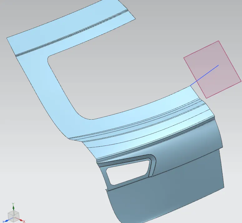
this class a surface was disjoint we joint all of them and remove unwanted surfaces
- INNER PANEL CREATION:
For creating innet panel we offseted the upper door in downward direction to 1.7mm and lower door to 80mm around to get The surface for creatig inner panel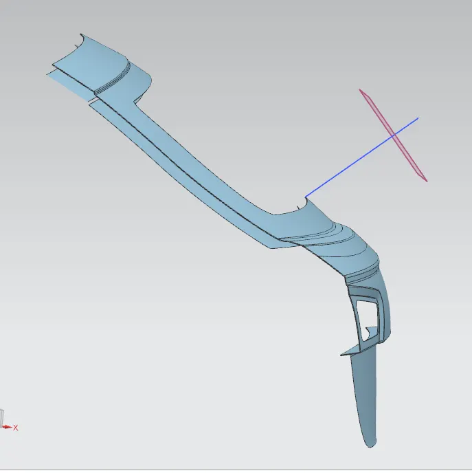
now we have created the inner panel flanges as shown in the below figure:
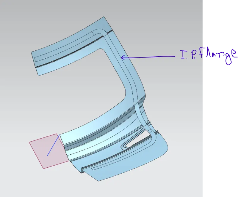
here we created a offset curve in face and offseted it to 40mm and again offsetit to 30mm and trim the unnecessary surfaces to get a desured flanges, some where we hAVE created through ccurve mesh to joint the flanges , or to obtaine desired curvature of the surface.
Now from the outer most edges of the surface we have etended the surface 35degree outward to a perticular length and then applied a face blend between them of 5 mm.
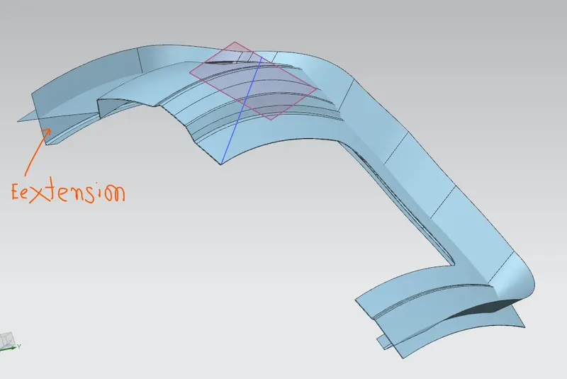

Now trim the working surfaces with this law extension, here we we will take a trim tool as the extension surfacefpr both upper door and lower door portion.
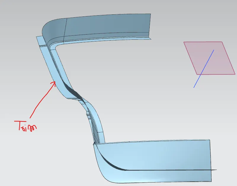
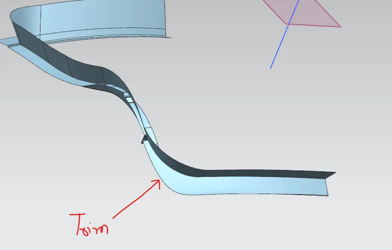
Now extrct the working surfces and offset it in downward direction to 1.7 mm 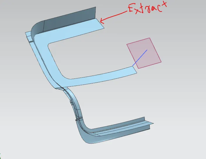
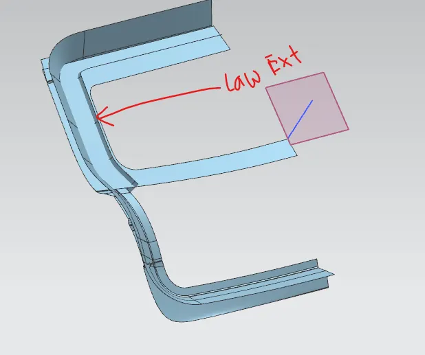
and do extend the flange from inner side at 35 degree and exted upto a lenghte which crosses the ofsseted surface sothat we can do trim and extend betweeen these two surfaces
here it looks when we do trim between them
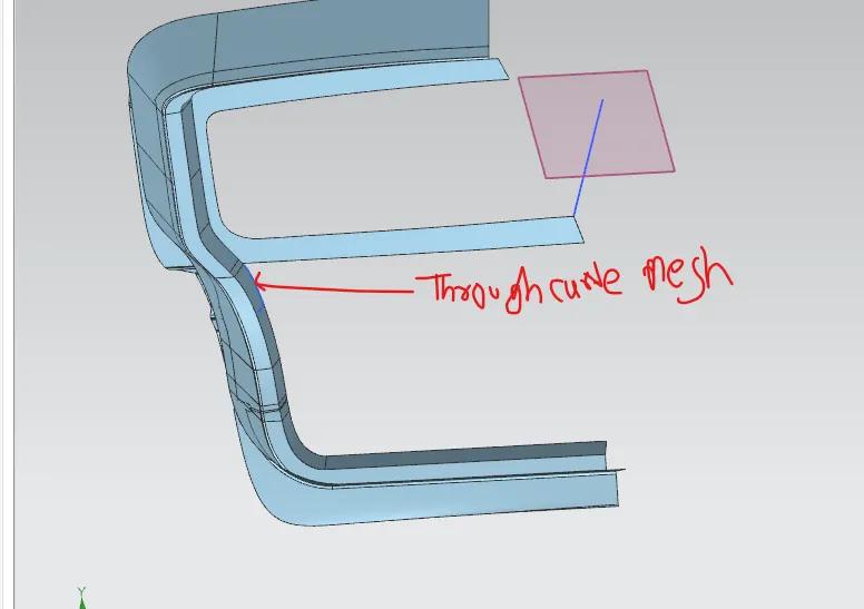
Now Extend the lower portion of the lange also at 35 degree and upto a length less than withe previous one because here the glanges are up at some distance , now creat the bridge curve betwee the fkanges and we will do the through curve mesh between the flanges and SEW them together.
Now create bridge curve between the upper surface and lower side of the flange and create a through curve meshe between the surfaces to get a surface connection between them here we will also adjust the the curvature of the bridge curve so that we have good aesthatic surfaces
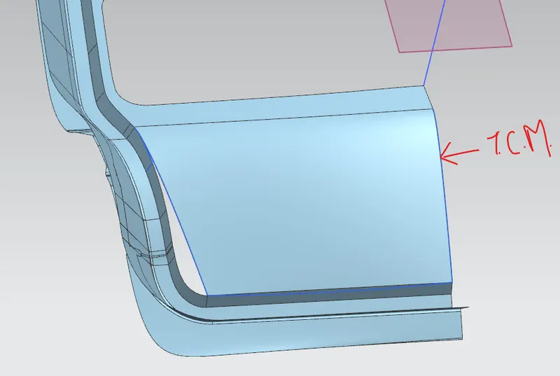
Now we can see that there is a gap between the flanges and surface we have just created now i have done extend the sheet upto a length do that it can crosses the other surface. Now trim the surfaces
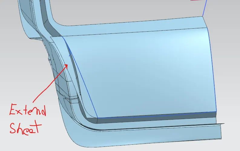
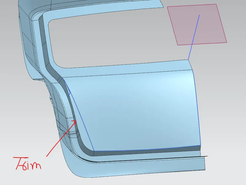
Now i have applied the face blends between the surface to a radious of5 mm and also face blend in the lowe area of the same radious
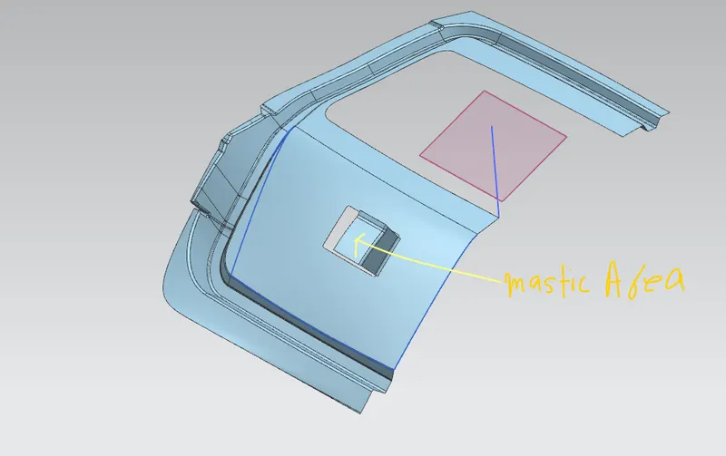
Now after we will create joining flange betweet the ineer panel and outer panel by using cut out and here we will give the space between outer panel and inner panel flange to 5 mm for the mastic to be placed there images are attached below
Now gone to sketche and created sketche for the embosses and cut outs for the latch and striker actuator and wiper mounting embosses see the below image:
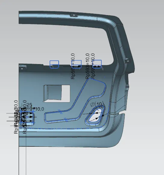
here is the final cut outs end embosses shown:
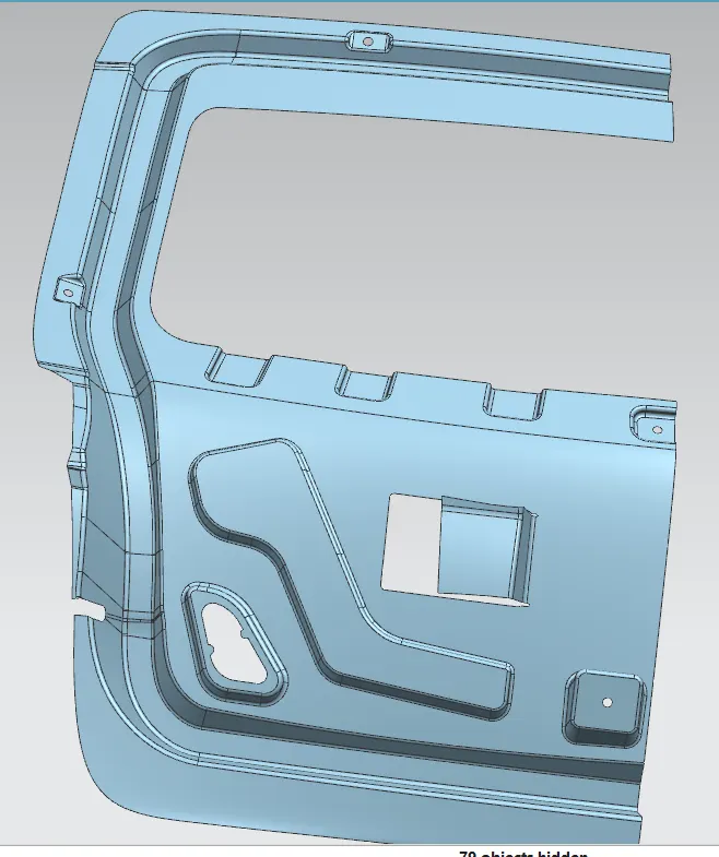
now i have mirror the surface after mirroring there was a gap beween the surfaces at the blends area so for remove this gap we deletethe mirror and extend the sheet from side edges to 3 mm and make a trim it with the plane which we will use as a mirroring plane now again mirror the surface and and hence gap are removed
after mirroring we give the thicken of the surface to0.75 mm towards the outer panel.
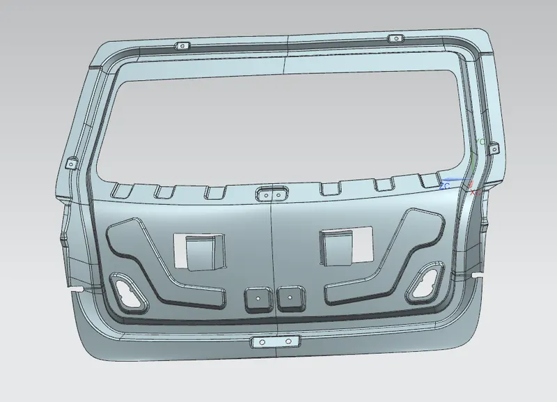
figure shows the final inner panel.
- DRAFT ANALYSIS:
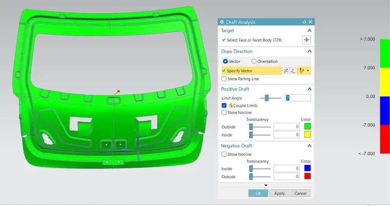
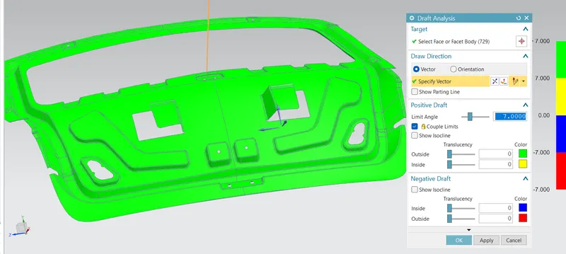
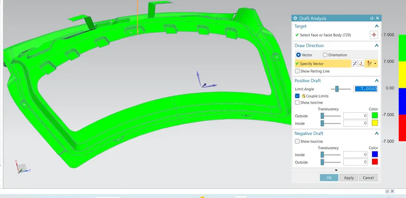
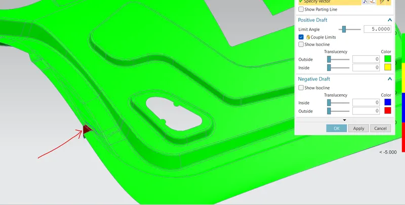
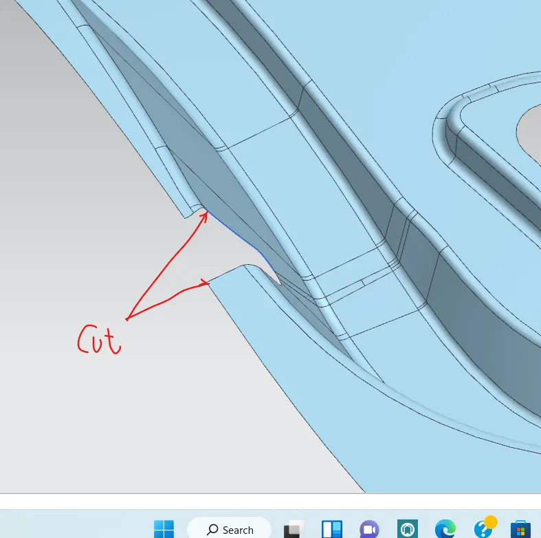
In some area we dont clear the draft analysis so we have removed the surfaces at that portion locally as shown in belo images
- OUTER PANEL OR HEMMING CREATION:
- The hemming is done for joining the outer panel with the inner paner a, a gap of 0.2mm is therein hemming between two surfaces for rubber sealent to be placed there hemming operation is done in OEMs with the help of roller as shown in below images:
-
Hemming is a forming operation in which the edges of the sheet are folded or folded over another part in order to achieve a tight fit. Normally hemming operations are used to connect parts together, to improve the appearance of a part and to reinforce part edges.
In car part production, hemming is used in assembly as a secondary operation after deep drawing, trimming and flanging operations to join two sheet metal parts (outer and inner) together. Typical parts for this type of assembly are hoods, doors, trunk lids and fenders.
The accuracy of the hemming operation is very important since it affects the appearance of the surface and surface quality. Material deformations, which occur during the hemming process, can lead to dimensional variations and other defects in parts. Typical hemming defects are splits or wrinkles in the flange, material overlaps in the corner areas or material roll-in. This is why it is important to use simulation tools in order to, on the one hand, better understand the hemming process and, on the other hand, significantly reduce the number of “trial and error” loops during tryout und production.
There are various types of hemming operations:
- Conventional die hemming
- Roll hemming
- CONVENTIONAL DIE HEMMING:
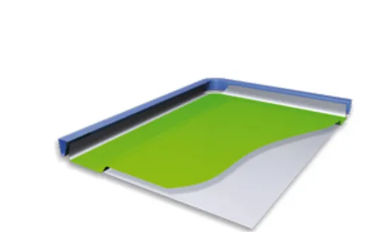
Conventional die hemming is suitable for mass production. In die hemming, the flange is folded over the entire length with a hemming tool. Normally the actual hemming is a result of a forming operation in which the flange is formed with a hemming tool after the drawing and trimming operations have been completed. The formed flange is then hemmed in several process steps. These steps include, for example, the pre-hemming and final hemming depending on the respective opening angle of the flange. Production plants for conventional die hemming are very expensive, but the cycle times are very low.
- ROLL HEMMING:
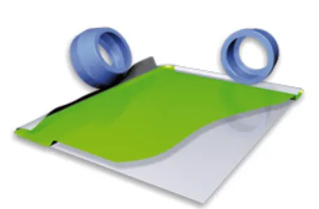
Roll hemming is carried out incrementally with a hemming roller. An industrial robot guides the hemming roller and forms the flange. Roll hemming operation can also be divided into several pre-hemming and final hemming process steps. Roll hemming is very flexible to use and tool costs are significantly lower as compared to those of conventional die hemming. However, the cycle times are much higher since the hemming is realized using a hemming roller which follows a defined path.
- HEMMING CREATION:
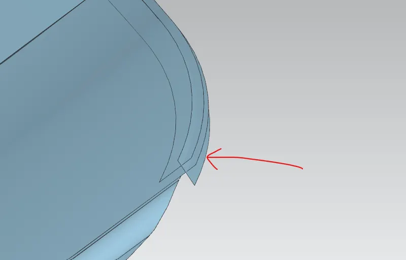
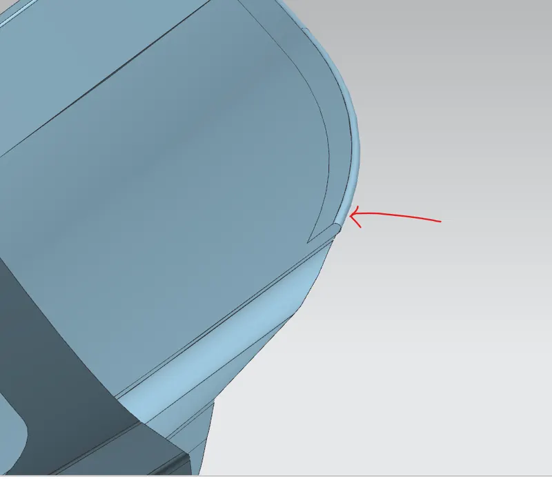
First i have created a low extension on the side edges of thr surface perpendicular to it and offset this extension 2 mm awaay from the surface and 6mm in the direction towards the surface . and again offset the surface 2.65mm lower to the surface and trim it with 6 mm extension surface keeping as a tool. after use three face blend , hence we get the hemming profile like this:
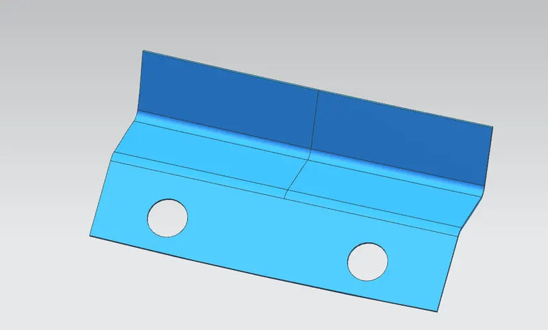
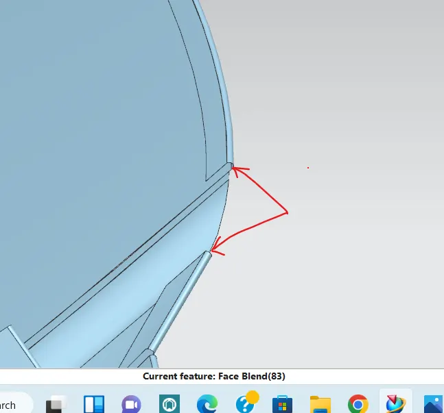
Now there were some critical areas where for hemming we used SWEPS Surface command to make the hemming between two hem durfaces as shown in below images:
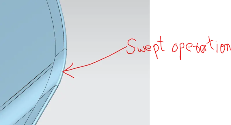
now i have mirror the surface after mirroring there was a gap beween the surfaces at the blends area so for remove this gap we deletethe mirror and extend the sheet from side edges to 3 mm and make a trim it with the plane which we will use as a mirroring plane now again mirror the surface and and hence gap are removed
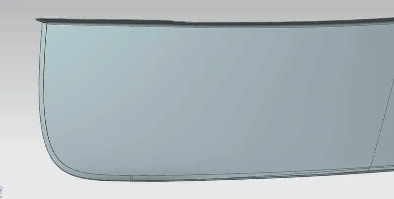
after mirroring we give the thicken of the surface to 0.75 mm towards the Inner panel.
Now same operation done in the creation of hemming in the lower side of the outer panel.
- GASTAY REIFORCEMENT CREATION:
Reinforcement is a device which is used to give strength of the sheet locally where we have removed surfaces or where we have to give any other part mounting.
Gastay reinfotcement is used to hold the gastay.
First we extract the surfaces where we have to create reinforcement and and trim it according to the recurirement and thicken the surfaces
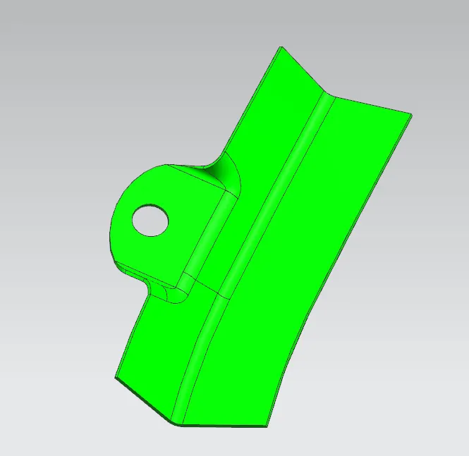
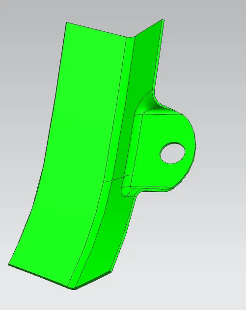
Left Hand Right Hand
- HINGE REINFORCEMENT:
Hinge reinforcement is that where we mount the hinges, one side of the hinge are attached back door and other side on the roof for easy opening and closing of the back door
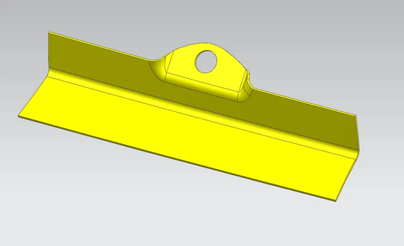
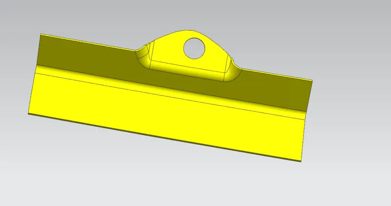
Left hand side Reinforcement Right hand side Reinforcement
- LATCH AND STRIKER REINFORCEMENT:
This reinforcement is used for locking purpose, this must be parallel with the locking assambly for this to achieve we draw a trajectory curve.