Design of backdoor
BACKDOOR DESIGN
The backdoor or tailgate is the rear most part of the automobile which opens upwards,downwards or sideways to give access to the luggage space or seating area. In most of the cars the backdoor opens upwards. It is hinged to the roof and a gas stay support fixed at the body side outer for keeping the backdoor in open position.
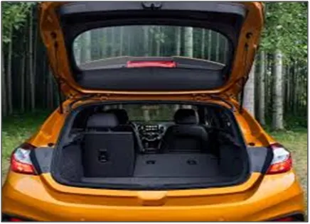
FIG 1. BACKDOOR
The material used in making the backdoor of car is mainly steel but nowadays Aluminium is also used in making the panels.
The main advantage of Aluminium over steel is that the density of Aluminium is very less as compared to steel so it reduces the overall weight of the car. But Aluminium is costly as compared to steel.
The main parts of the backdoor are:
Outer Panel
Inner Panel
Hinge Reinforcement
Gas Stay Reinforcement
Wiper Motor Reinforcement
Latch and Striker Reinforcement
OUTER PANEL:
The class A surface of the outer panel is provided to us by the styling team. From this surface we have to develop the inner panel and all the other parts and finally assemble them.
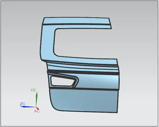
FIG 2. CLASS A SURFACE
Firstly we have to check for any surface discontinuity and irregularities. Small errors can be rectified but if there is any major error contact the styling team.
INNER PANEL:
Considering the class A surface as reference we have to create the inner panel of the backdoor. The most important part of the inner panel is the sealing flange which decides how the backdoor will be mounted at the rear side of the car. It also seals the rear side of the car and prevents the entry of dust and water from entering inside the car. The width of the sealing flange should be at least 25mm.
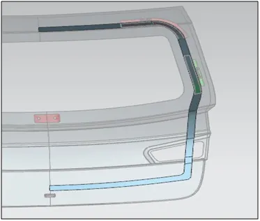
FIG 3. SEALING FLANGE
Embosses and Cut Outs:
The embosses are provided in the inner panel for strengthening the part and also to dissipate the forces in case of rear collision to the outside of the car.. The cut outs are basically access holes for the fitment of wiper motor and latch and striker motor. These are fitted mainly after the assembling of the inner panel with the outer panel. Sometimes holes are also provided in the panel to maintain the CG of the panel.
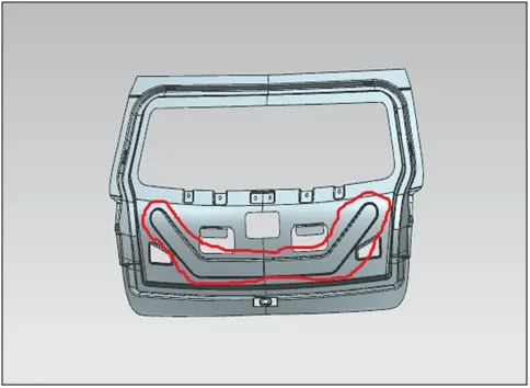
FIG 4. Y EMBOSS
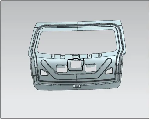
FIG 5 WIPER MOTOR ACCESS HOLE
Embosses are also created in the area of the backdoor where the plastic parts are fitted.
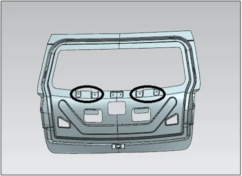
FIG 6. EMBOSSES FOR FITMENT OF PLASTIC COMPONENTS
The inner panel is mainly fixed to the outer panel by the process of hemming but still there will be rattling noise. So to avoid that extensions are created in the inner panel which is fixed to the outer panel by applying mastic seal. While designing make sure to give 4-5 mm distance from the outer panel so that mastic seal can be applied in that area.
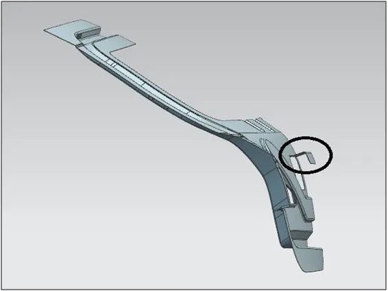
FIG 7. EXTENSIONS IN THE INNER PANEL
Embosses for the fitment of hinge, gas stay, wiper motor and latch and striker are created on the inner panel.
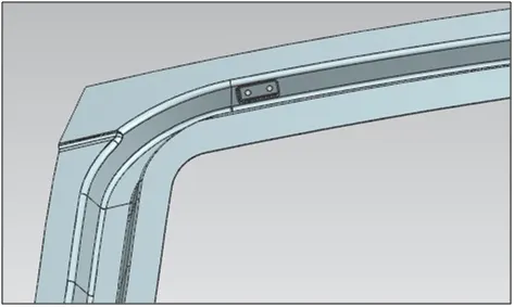
FIG 8. HINGE EMBOSS
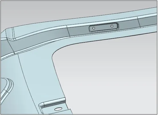
FIG 9. GAS STAY EMBOSS
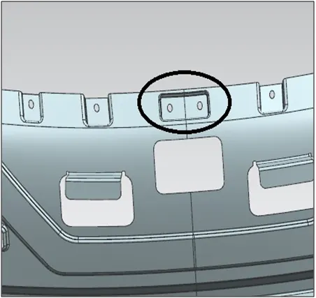
FIG 10. WIPER MOTOR EMBOSS
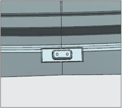
FIG 11. LATCH AND STRIKER EMBOSS
After creating all these the inner panel is thickened to 0.75 mm.
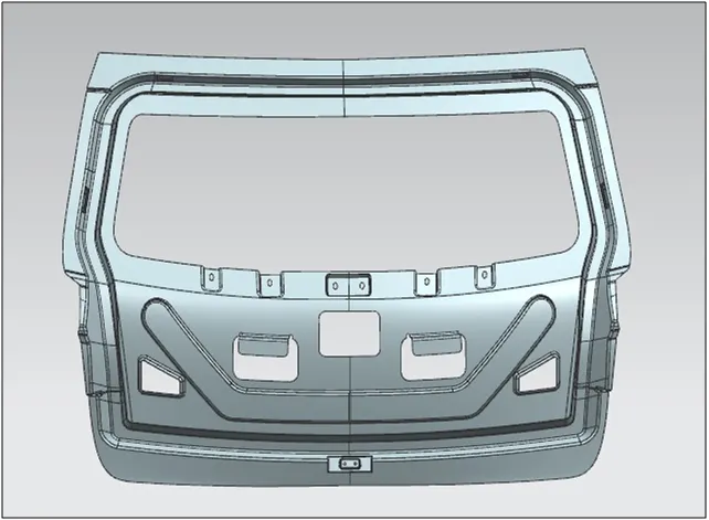
FIG 12. INNER PANEL FRONT VIEW
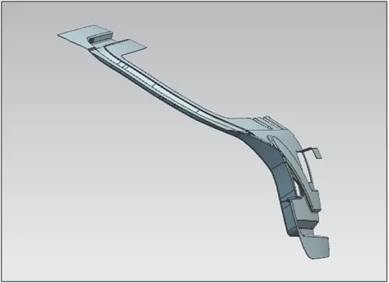
FIG 13. INNER PANEL SIDE VIEW
After that we check whether the inner panel that we have designed can be deep drawn. We use Draft analysis for this purpose. It is based on different colour zones that indicate whether the part can be manufactured or not.
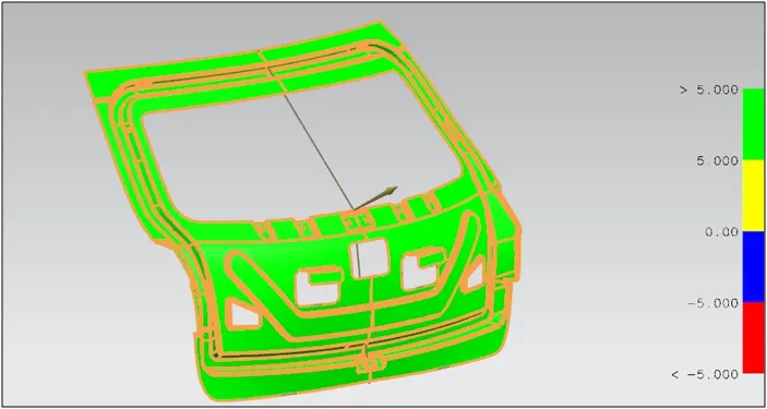
FIG 14. DRAFT ANALYSIS
HINGE REINFORCEMENT:
The backdoor is hinged to the roof. The hinge may be fitted outside the backdoor or inside the backdoor. Reinforcements are designed to strengthen the localised part where the hinge is assembled.
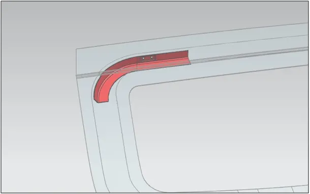
FIG 15. HINGE REINFORCEMENT
GAS STAY REINFORCEMENT:
Gas Stay is that part which helps the backdoor to stay in the open position. It is either motor operated or manually operated.
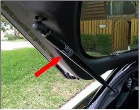
FIG 16. GAS STAY IMAGE
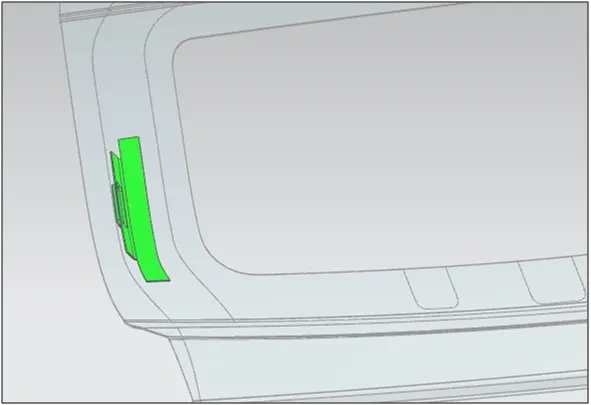
FIG 17. GAS STAY REINFORCEMENT
WIPER MOTOR REINFORCEMENT:
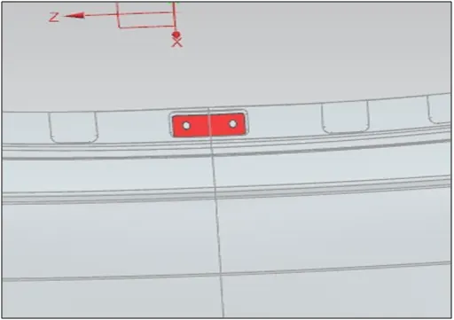
FIG 18. WIPER MOTOR REINFORCEMENT
LATCH AND STRIKER REINFORCEMENT:
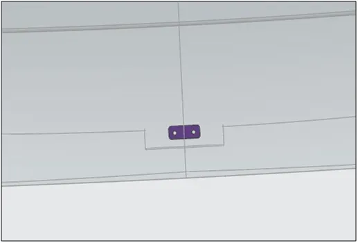
FIG 19. LATCH AND STRIKER REINFORCEMENT
The fitment of latch and striker plays an important role in the designing of backdoor. At first the hinge is fixed, and by taking the centre point of the hinge axis and the centre point of the latch, draw a circle. the centre of the latch should be perpendicular to the circular trajectory.
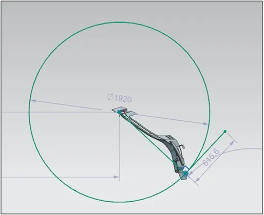
FIG 20. PLACEMENT OF LATCH AND STRIKER
The inner panel is joined to the outer panel by the process of hemming.
HEMMING
At the corners the outer panel and the inner panel are joined together by hemming. No type of welding is done because it leaves a mark on the outer panel and damages the aesthetic beauty of the car.
Hemming is a forming operation in which the edges of the sheet are folded or folded over another part in order to achieve a tight fit. Normally hemming operations are used to connect parts together, to improve the appearance of a part and to reinforce part edges.
There are various types of hemming operations:
Conventional Die Hemming: In conventional die hemming, the flange is folded over the entire length with a hemming tool.
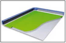
FIG 21. CONVENTIONAL DIE HEMMING
Roll Hemming: Roll hemming is carried out incrementally with a hemming roller. An industrial robot guides the hemming roller and forms the flange.
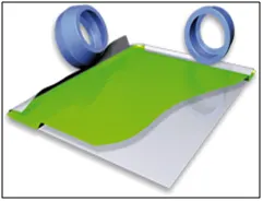
FIG 22. ROLLER HEMMING
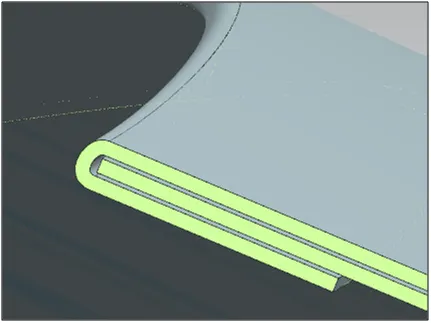
FIG 23. HEMMING
After the assembling of the whole parts the final backdoor model:
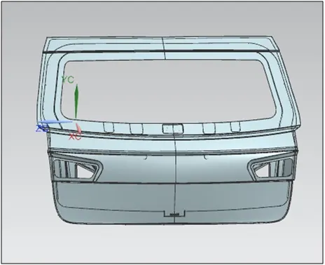
FIG 24.VIEW 1
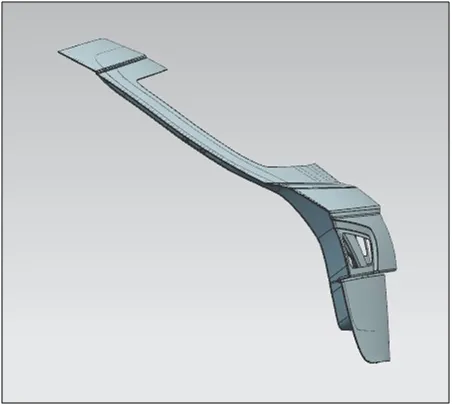
FIG 25. VIEW 2
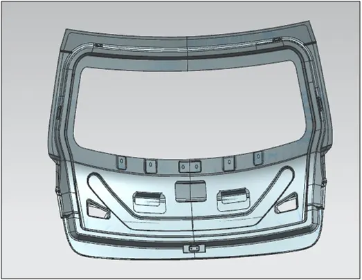
FIG 26. VIEW 3
Thus the backdoor model was successfully created in NX CAD
******