DESIGN AND MODELLING OF AN AUTOMOTIVE FRONT FENDER IN NX-CAD
INTRODUCTION:
Front fender is a part located on each side of the vehicle between the bumper and the A-pillars. It is manufactured in-house.
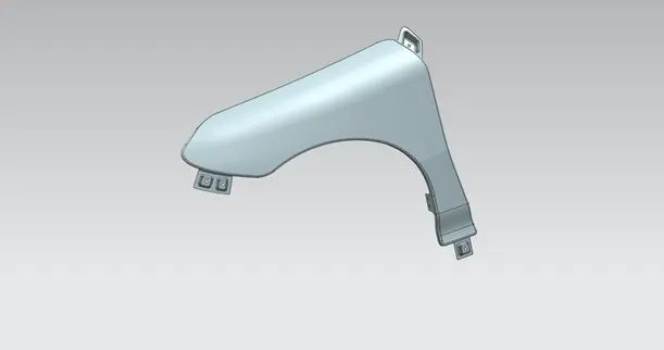
Major role of fender is to avoid entry of debris such as mud, sand, rocks and other liquids present on the road surface. Also helps to the pedestrian safety up to some extent.
There are basically two types of front fender: Full bumper type and Half bumper type
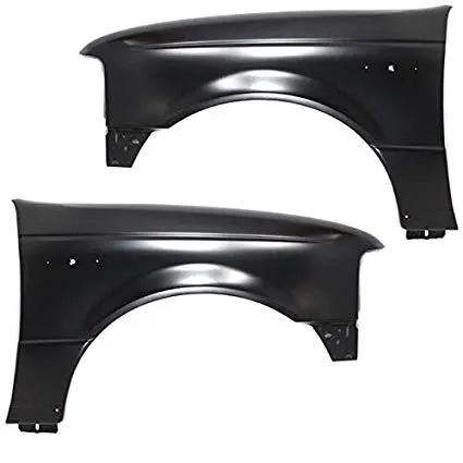
The full bumper type (shown above) covers more wheel arch as compared to the half bumper type (shown below)
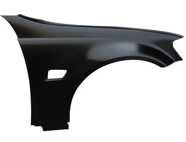
The fender is mounted/has mounts at the following points in an automobile:
- Drip
- A-pillar
- Sill
- Bumper
- Splash mountings
I. DRIP MOUNT
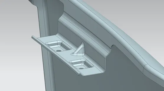
The drip area is manufactured as per some standard design requirements as shown in image below. It gets attached to the engine compartment using a contact bracket. The drip is manufactured by punching process.
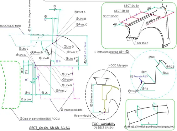
Also, the maximum allowable height for drip area is approximately 40mm for reason that any sheet metal longer than this, when punched experiences spring-back effect and hence may reduce its overall strength. Also, there must be a minimum 10mm clearance (as shown in figure above) between engine room and drip end.
II. A-PILLAR MOUNTING:
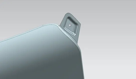
The A-pillar mounting is used to attach the front fender to A-pillar.
III. SILL MOUNTING:
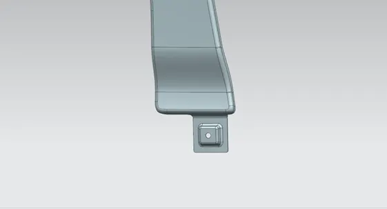
Sill mounting attached the front fender to the lower-most portion of automotive body i.e. Sill.
IV. BUMPER MOUNTING:
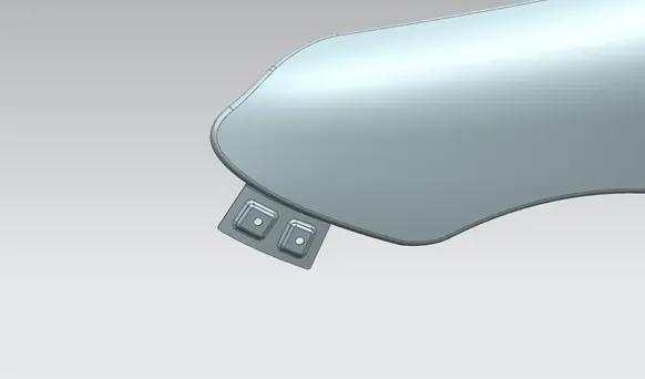
The bumper mounting is used to attach front fender to the front bumper. A 150 mm gap is left to accommodate headlight assembly while designing the drip. (Refer figure in Drip mounting description)
V. SPLASH MOUNTINGS:
The splash mountings (also called as baffle mountings) are just normal hole cut-outs in the extensions along wheel arch, which are used to attach the baffle to avoid the entry of dirt and liquids present on the road surface to enter into engine compartment.
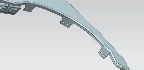
Along with all these mountings a front fender may/may not have a cutout for the turn indicator light.
CONCLUSION:
Thus a front fender has been designed and modelled by considering all the necessary requirements. It can be further sent to manufacturing.