Design and Assemble Of American Chopper
Design & Modelling of American chopper using SOLIDWORKS
Introduction: Choppers bikes are motorcycles featured on the television series of American Chopper for a specific corporate or celebrity customer. The function of motorcycle usually takes a backseat to the presentation of the theme, and these motorcycles attract attention solely on the premise of the theme itself.
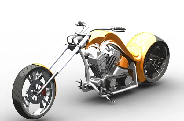
American chopper Bike
Objective: The objective of this project is used to create a model of different parts of American chopper bike like chassis, engine, wheels, etc…., and assemble with different parts of chopper and to create photorealistic model of chopper and rendering the model by using software called solid works photo view 360.
Part Modelling: You can create a part by using a conceptual sketch through solid feature modelling and modify parts through direct and by using a blue print setups.
The main parts of chopper are: The following parts of the chopper are used for model and assembly in solid works.
- Transmission belt
- Kick stand
- Front fender
- Rear fender
- Oil tank
- Chain
- Pedal
- Front wheel
- Rear wheel
- Front fork
- Chassis
- Engine
- Gas tank
- Transmission belt: The main purpose of transmission belt is used to transmit power which is developed inside the engine to gear box with maximum efficiency.
Features used to create a Transmission belt are:
- Sketch
- Offset
- Extrude
- Fillet and
- Apperances
The following procedure is used to create a Transmission belt:
1. First open solid works then select new part to create new model
2. Then change the default names of planes as
Front plane in to Front plane Transmission belt.
Top plane in to Top plane Transmission belt.
Right plane in to Right plane Transmission belt.
3.Then select front plane transmission belt to create a 2D sketch and draw a sketch and give the dimensions, relations to sketch for fully defined.
4. Then offset the sketch with some distance by using offset command then exist the sketch.
5. Then extrude command is used to convert 2D sketch into 3D model.
6. Then fillet is applied to belt as per requirements and model of transmission belt is created and change appearance of belt and save the model.
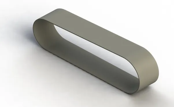
Transmission Belt
- Kick stand: The kick stand is usually more convenient for quickly propping the bike up when parking for a short time since you don't have to lift the bike at all to use it. It can be easier to get a bike off the kick stand than off the centre stand on sloping ground in a controlled fashion, especially if the bike is heavy.
Features used to create a Kick stand are:
- Sketch
- Loft
- Dome
- Extrude boss
- Extrude cut
- Fillet
- Split
- Appearances
The following procedure is used to create a Kick stand:
1. First open solid works then select new part to create new model
2. Then change the default names of planes as
Front plane in to Front plane.
Top plane in to Top plane.
Right plane in to Mid plane.
3. Then select midplane for sketching.
4. Then draw the 2D sketch by using sketch commands, spline and trim commands and apply dimensions, relations for fully defined the sketch.
5. Then create new planes and draw ellipse in new planes as per required.
6. Then use loft command for create a loft to kick stand.
7. Extrude cut command is used to cut unwanted parts in the kick stand and change the appearance of kick stand and save the model.
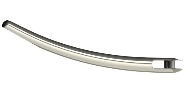
Kick stand
- Front fender: The front fender is mounted on a above the front wheel, which is used to protect rider and chopper other parts from dust, mud and other particles.
Features used to create front fender:
- Sketch
- Offset entities
- Trim entities
- Revolve
- Dynamic mirror
- Split
- Fillet
- Appearance
The following procedure is used to create a Front fender:
1. First open solid works then select new part to create new model
2.Then change the default names of planes as
Front plane in to vertical plane Front fender
Top plane in to centre plane Front fender
Right plane in to Mid-plane Front fender
3. Then select vertical plane front fender for sketching
4. Then draw the 2D sketch by using sketch commands, spline and trim commands and apply dimensions, relations for fully defined the sketch.
5. Then change the appearance of front fender and save the model.
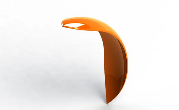
Front fender
- Rear fender: Its primary purpose is to prevent sand, mud, rocks, liquids, and other road sprayfrom being thrown into the air by the rotating tire. Fenders are typically rigid and can be damaged by contact with the road surface.
Features used to create a Rear fender:
- Sketch
- Offset entities
- Trim entities
- Revolve
- Apperance
The following procedure is used to create a Rear fender:
1. First open solid works then select new part to create new model
2. Then change the default names of planes as
Front plane in to vertical plane Rear fender
Top plane in to centre plane Rear fender
Right plane in to Mid-plane Rear fender
3. Then select centre plane Rear fender for sketching.
4. Then draw the 2D sketch by using sketch commands, spline and trim commands and apply dimensions, relations for fully defined the sketch.
5. Then change the appearance of front fender and save the model.
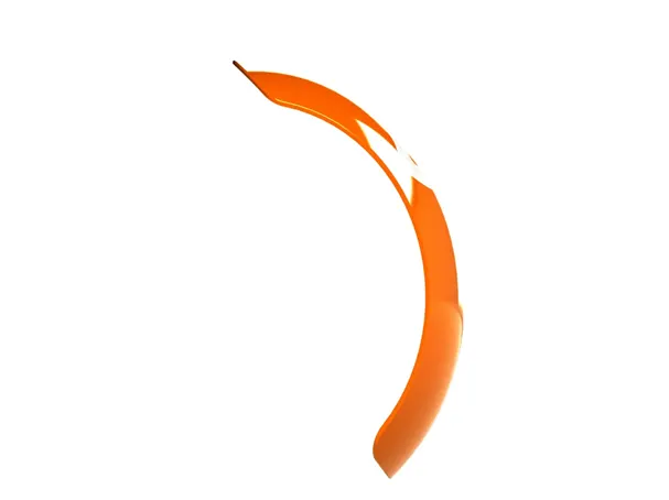
Rear Fender
- Oil Tank: The oil tank is hollow section, and main purpose of oil tank is used to store the oil and supply the oil to engine while run the vehicle.
Features used to create a Oil tank:
- Sketch
- Boss extrude
- Combine
- Shell
- Fillet
- Appearance
The following procedure is used to create a Oil tank:
- First open solid works then select new part to create new model
- Then change front plane into midplane oil tank and select top plane for sketching
- Then draw 2D sketches by using sketch commands, then add dimensions and relations as we required for fully defined the sketch, then combine the model.
- Then do shell and fillet commands and change the appearances and save the model.
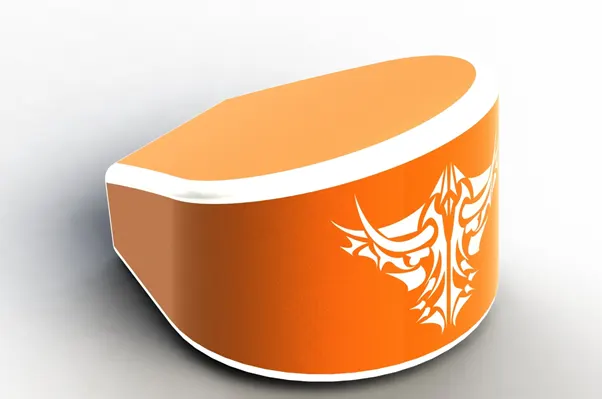
Oil tank
- Chain: Chain is a way of transmitting mechanical power from one place to another. It is often used to convey power to the wheels of vehicle, particularly bicycles and motorcycles. Most often, the power is conveyed by a roller chain, known as the drive chain or transmission chain, passing over a sprocketgear, with the teeth of the gear meshing with the holes in the links of the chain.
Features used to create a chain:
- Sketch
- Boss extrude
- Fillet
- Curve driven pattern
- Mirror
- Appearance
The following procedure is used to create a Chain:
1. First open solid works then select new part to create new model
2. Then change the default names of planes as
Front plane in to Midplane chain
Top plane in to centre plane chain
Right plane in to Front plane chain
3. Then draw 2D sketches by using the sketch commands, and give dimensions and relations as we required for fully defined the sketch.
4. Then use curve driven pattern and fillet the chain.
5. Then change the appearance of chain and save the model.
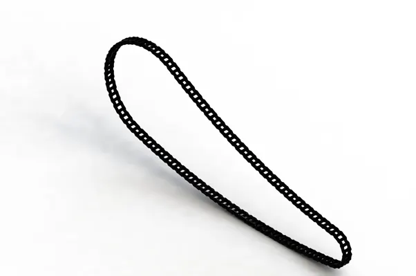
Chain
- Pedal: The main purpose of pedal is that place the leg on top of that for resting position and some times used for changing the gears by keeping leg on pedal.
Features used to create a chain:
- Sketch
- Boss extrude
- Revolve
- Dome
- Fillet
- Chamfer
- Linear pattern curve
- Appearance
The following procedure is used to create a Pedal:
- First open solid works then select new part to create new model
- Then select front plane for 2D sketch.
- Then draw all 2D sketches by using sketch commands, and add dimensions and relations as per required for fully defined the sketch.
- Then apply dome, fillet and chamfer commands to sketch.
- Then add linear pattern curve for sketch and change the appearance of sketch.
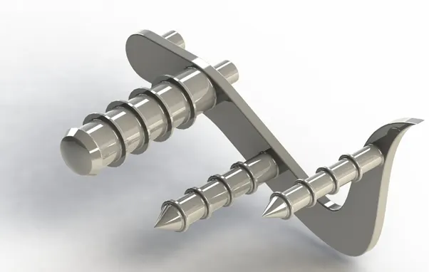
Pedal
- Front wheel: Motorcycle wheels are made to cope with radial and axial forces. They also provide a way of mounting other critical components such as the brakes, final drive and suspension. Wheels, and anything directly connected to them, are considered to be unsprang mass. Traditionally motorcycles used wire-spoked wheels with inner tubes and pneumatic tyres.
Features used to create a Front wheel:
- Sketch
- Revolve
- Boss extrude
- Cut extrude
- Circular pattern
- Linear pattern
- Combine
- Trim
- Fillet
- Chamfer
- Appearance
The following procedure is used to create a Front wheel:
- First open solid works then select new part to create new model
- Then select front plane for 2D sketch.
- Then draw all 2D sketches by using sketch commands, and add dimensions and relations as per required for fully defined the sketch.
- Then apply linear pattern, circular pattern, fillet, chamfer combine commands to sketch.
- Then change the appearance of front wheel.
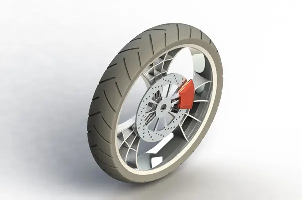
Front wheel
- Rear wheel: The chain is connected between the engine and rear wheel to drive the vehicle which the power is develop inside the engine. The rear wheel has disc and sprocket attachment.
Features used to create a Rear wheel:
- Sketch
- Revolve
- Cut extrude
- Boss extrude
- Circular pattern
- Combine
- Revolve cut
- Fillet
- Chamfer
- Appearance
The following procedure is used to create a Rear wheel:
- First open solid works then select new part to create new model
- Then select front plane for 2D sketch.
- Then draw all 2D sketches by using sketch commands, and add dimensions and relations as per required for fully defined the sketch.
- Then apply linear pattern, circular pattern, fillet, chamfer combine commands to sketch.
- Then change the appearance of rear wheel.
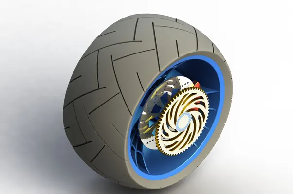
Rear wheel
- Front fork: The front fork prevents excessive weight on the front wheel during drastic sudden applications the break, softens bumping when driving on rough road surfaces. The front fork maintains proper damping through traction with the road surface.
Features used to create a Front fork:
- Sketch
- Revolve
- Boss extrude
- Fillet
- Linear pattern
- Cut extrude
- Dome
- Revolve cut
- Project curve
- Mirror
- Combine
- Sweep
- Split
The following procedure is used to create a Front fork:
- First open solid works then select new part to create new model
- Then select front plane for 2D sketch.
- Then draw all 2D sketches by using sketch commands, and add dimensions and relations as per required for fully defined the sketch.
- Then mirror the object and change the appearance of object.
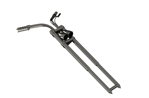
Front fork
- Chassis: A motorcycle’s chassis or frame forms its skeleton. All the components of a motorcycle, like the suspension, wheels, fuel tank, seats, handlebars etc, are attached to this base structure which lends a motorcycle its strength and ability to handle well. Motorcycle frames come in a variety of materials and shapes, based on the budgetary and performance-related limits of the end product.
Features used to create a Chassis:
- Sketch
- Convert entities
- Project curve
- Offset
- Trim
- Sweep
- Split
- Revolve
- Cut extrude
- Fillet
- Combine
- Mirror
- Chamfer
- Dome
The following procedure is used to create a Chassis:
1. First open solid works then select new part to create new model
2. Then change the default names of planes as
Front plane in to Midplane chassis
Top plane in to bottom plane chassis
3. Then select midplane chassis for sketch then bring the sketch picture in the midplane chassis and then change the x and y directions positions and transparency as per required.
4. Then exist the sketch and rename the sketch as blueprint chopper.
5. Then draw the 2D sketches by using planes, and sketch commands and give dimensions and relations as per required to fully defined the sketch.
6. Then change the appearance of chassis and save the model.
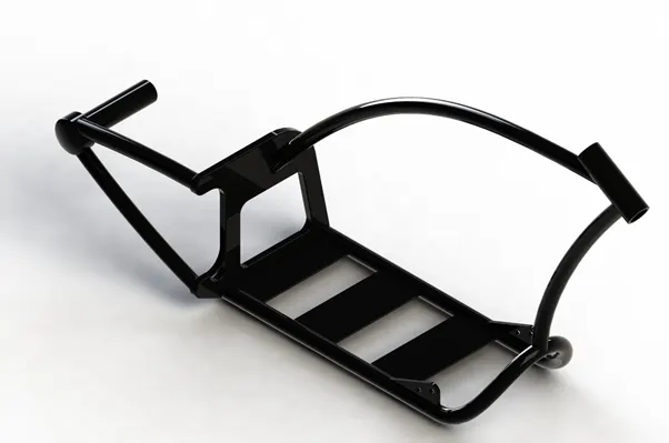
Chassis
- Engine: The engine is prime mover of any vehicle; it converts the chemical energy in to heat energy by burning the air fuel mixture inside the engine cylinder. Motorcycle engines are typically two-strokeor four-stroke internal combustion engines, but other engine types, such as Wrankels and electric motors, have been used. Then heat energy is converted in to mechanical energy by rotating the parts like flywheel, clutch, gear box etc…. then power is transmitted to rear wheels.
Features used to create a Engine:
- Sketch
- Boss extrude
- Revolve
- Fillet
- Circular pattern
- Dome
- Cut extrude
- Chamfer
- Linear pattern
- Mirror
- Swept
- Project curve
- Split
The following procedure is used to create a Engine:
- First open solid works then select new part to create new model
- Then select front plane for sketch and then bring the sketch picture in the midplane chassis and then change the x and y directions positions and transparency as per required.
- Then exist the sketch and rename sketch in to blueprint chopper.
- Then draw the 2D sketches by using planes, and sketch commands and give dimensions and relations as per required to fully defined the sketch.
- Then change the appearance of Engine and save the model.
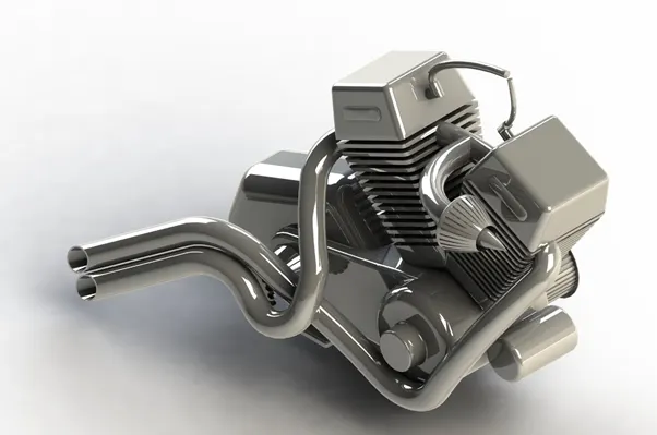
Engine
- Gas tank: The main purpose of gas tank is used to store the gas. It supplies the gas when engine required.
Features used to create a Gas tank:
- Sketch
- Surface sweep
- Surface trim
- Project curve
- Surface loft
- Surface boundary
- Surface knit
- Split line
- Mirror
- Surface extrude
- Fillet
- Cut sweep
- Shell
The following procedure is used to create a Gas Tank:
1. First open solid works then select new part to create new model.
2.Then change the default names of planes as
Front plane in to Midplane fuel tank
Top plane in to bottom plane fuel tank
Right plane in to front plane fuel tank
3. Then select midplane fuel tank for sketch, then bring the sketch picture in the midplane fuel tank and then change x & y directions positions and transparency as per required.
4. Then exist the sketch and rename sketch in to under lay fuel tank.
5. Then draw the 2D sketches by using planes, and sketch commands and give dimensions and relations as per required to fully defined the sketch.
6. Then change the appearance of Gas tank and save the model.
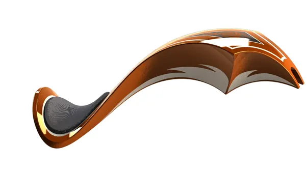
Gas tank
Assembly of chopper: The main purpose of assembly of chopper is that assembly the all individual parts with suitable mates.
The following procedure is used to create a Assembly of American chopper:
- Click on file then open all the components and then open assembly file.
- Then open insert components and then select chassis and insert then ok.
- Then insert engine manually in rough position, then select front plane of engine and front plane of assembly and make coincident each other
- Then select bottom face of motor and one of plate of frame and make coincident each other and then give distance between front face of plate and frame. Then replace front plane of assembly to midplane chassis then mate and save.
- Then expand part and rebuild dimensions as per orientation and do collapse items.
- Then insert pedal manually inside of assembly to position and then select outside pedal and inside of frame plate and make concertic and coincident. Again, open the engine part and then modify as per orientation and then open assembly file and save.
- Then mirror the pedal by using mirror component as per orientation and save.
- Then insert the kick stand to nearest point of orientation and then mate the plate and kick stand. then make parallel between midplane of kick stand plate of frame and give the angle as per required and save.
- Then insert transmission belt and drag in to the closest position and select belt and pulleys and make concetric each other and then select two outsides face of pulley and then go to advance mate then select two faces of belt and pulley and then mate and then modify the belt dimensions as per orientation and then collapse items and save
- hen insert oil tank and select bottom face of oil tank and top face of motor and make coincident and then select midplane of oil tank and midplane of chassis and make coincident and then save.
- Then insert rear wheel in to nearest place and then change y direction as per orientation and then concetric between inside of wheel and axle.
- Then select right plane of rear wheel and midplane of chassis and make coincident and then select right plane of chassis and front plane of rear wheel and make parallel and then collapse items and save.
- Then insert rear fender in correct orientation by changing Y and Z directions and then select the one side of fender and tire face and make concentric and then select midplane of Rear fender and midplane of chassis and make coincident and again select plane of rear fender and right plane of chassis and make parallel and save.
- Then insert the chain to nearest place and then select midplane of chain and midplane of chassis and make parallel to each other, Then mate the chain and sprocket with each other and then collapse items and save.
- Then insert gas tank in the closest place and then select front plane of fuel tank and plane 2 of chassis and make coincident each other and then select bottom plane of fuel tank and bottom plane of chassis and then make coincident and then midplane of fuel tank and midplane of chassis make coincident and modify the one of coincident mate as per orientation and save.
- Then insert front fork to front face of model and then select stem of fork and front part chassis and make concentric each other.
- Then mate the upper and lower arms and top and bottom of section and control the angle by using mate command between front plane of fork and midplane of chassis and select midplane of chassis and front plane of fork make parallel and collapse items and save.
- Then insert front wheel by rotating Y direction and make concerntric with between wheel and axle.
- Then create a plane by using roll back feature tree and midplane of fork and right plane of wheel and vertical plane of front fork and make coincident each other and save.
- Then insert front fender by using changing direction of Y direction as per orientation.
- Then select vertical plane front fender and vertical plane fork and make coincident and then select centre plane of front fender and top plane of wheel and make coincident and midplane of fender and right plane of wheel make coincident and collapse items and save.
- Then edit chassis and chain as per orientation and save the file.
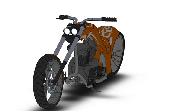
Assembly of chopper