Cyclone Separator Challenge
AIM:-
To conduct an Analysis on a Cyclone separator under different conditions and to calculate the separation efficiency and pressure drop.
INTRODUCTION:-
Cyclone separators are devices that employ centrifugal force by spinning gas stream to separate a particle from the carrier gas. It is also a dust collector which is used for separating the particles from exhaust gases in industries. It is used to separate particles ranging from 1Oµm to 1OOµm. There are different types of cyclones but cyclone with tangential inlet is quite popular. Cyclones are used for the removal of large particles for both air pollution control and process use. Application in extreme conditions includes the removal of coal dust in a power plant and the use as a spray dryer or gasification reactor.
THEORY:
ANSYS CFD solvers are based on the finite volume method,
- The domain is discretized into a finite set of control volume.
- General conservation equations for mass, momentum, energy, species, etc. are solved on this set of control volumes.
- Partial differential equations are discretized into a system of algebraic equations.
- All algebraic equations are then solved numerically to render the solution field.
Initially, the process involves three major Categories,
Pre-Processing
- Geometry
- Mesh
- Physics
- Solver Settings
Solve
- Compute solution.
Post Processing
- Examine results.
Operation
Cyclones works on the centrifugal separation principle where exhaust gas coming out from factories contains dust particles. This incoming gas is forced to flow through the tangential inlet. Then, it reaches the cylindrical portion where linear flow now gets transformed into swirling motion i.e swirl (outer vortex) is created. During swirling, flow particles come in contact with the wall and they lose their momentum resulting fall into a dust collector due to surface roughness of the wall and conical portion.
The gas due to the centrifugal force moves towards the outer boundary and the outer vortex is maintained. Simultaneously, the swirl continues towards the end and reverses its direction and the inner vortex is created. The upward movement is mainly due to the low density of the gas, and we know that gas always travels from low pressure to high pressure. The cleaner gas comes out of the vortex finder.
Geometry
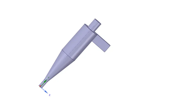
- The following Geometry is imported into the SpaceClaim.
- Then Each part is separated into different components.
- Then using the Volume extract tool the volume of the fluid is extracted.
Meshing
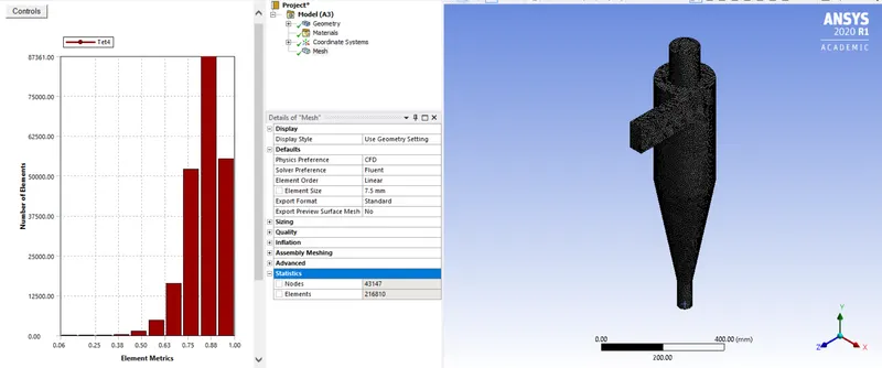
- Initially, we are going to name various components of the Graphics accordingly to set proper values for them.
- Then for meshing, we are going to be using the 0.75 mm element size.
Setup:-
- We are going to use Pressure Based solver.
- Under Steady-state conditions.
- We are going to use the -Epsilon RNG model since it captures the swirl clearly along with swirl dominated option.
- Enable Gravity along the Y-axis as -9.81 m/s2.
Discrete Phase Model (DPM):
- DPM is used when the flow of the discrete phase (particles) with a continuum is being modeled. DPM is used to track individual particles through the continuum fluid.
- Fluent allows us to simulate a discrete second phase n a Lagrangian frame of reference along with solving transport equations for the continuous phase. This second phase consists of spherical particles (which may be taken to represent droplets or bubbles) dispersed in the continuous phase.
- Here, in this case, solid particle size ranging from 1µm to 1Oµm being simulated as a discrete phase in a continuum.
- Injection of a solid particle will be done as:
Injection Type- Surface Release from surfaces
Inlet Particle type- Inert
Material- Anthracite (Uniform Diameter distribution)
CASE-1
Inlet-
Velocity magnitude- 3 m/s (For CASE-1)
DPM- Reflect
Outlet dustbin
Type- Pressure Based Gauge Pressure- O Pa DPM- Trap
Outlet Top
Type- Pressure Based Gauge Pressure- O Pa DPM- Escape
Wall-Volume_volume-
Wall Motion- Stationary Wall Shear Condition- No-slip DPM- Reflect
Method:
Turbulent Kinetic energy and Turbulent Dissipation Rate set to Second-Order UP-wind for greater accuracy in swirling flows.
The solution has been initialized using the "Standard Initialisation Method".
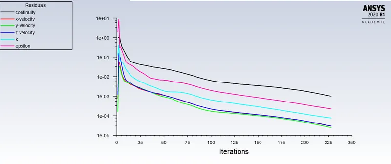
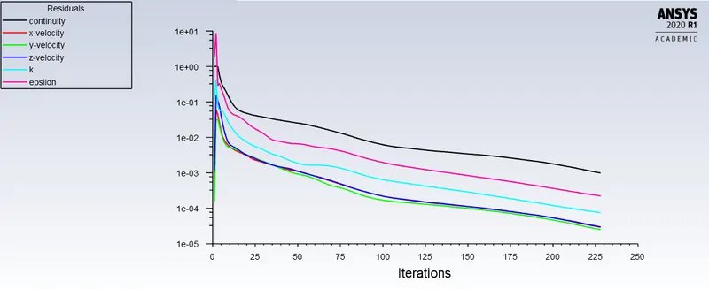
Case 1a (3micrometers) Case 1b (5micrometers)
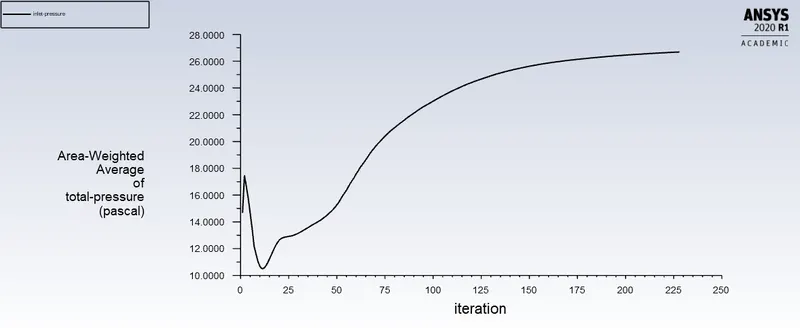
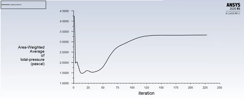
Case 1a (3micrometers)inlet total pressure Case 1a (3micrometers) outlet total pressure
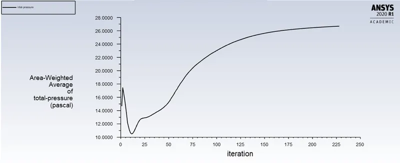
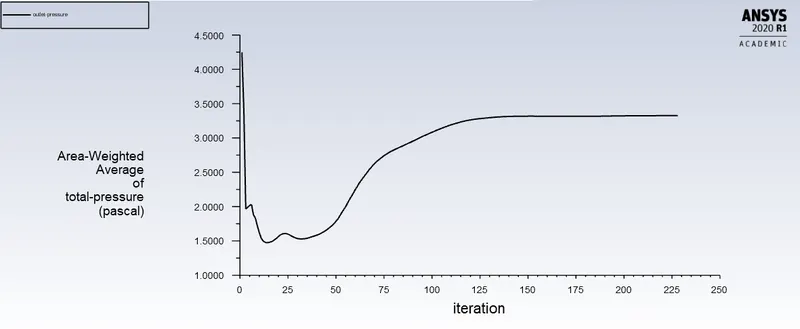
Case 1b (5micrometers)inlet total pressure Case 1b (5micrometers) outlet total pressure
Seperation/Collection efficiency
It is defined as a fraction of particles of a given size collected or trapped in the cyclone, compared to those of that size going into the cyclone. It is most properly defined for given particle size.
Collection efficiency of cyclone separator increases with increasing particle mean diameter and density; increasing gas tangential velocity; decreasing cyclone diameter; increasing cyclone length; extraction of gas along with solids through the cyclone legs.
Here, in our study we have summarised the particle data obtained from the simulation as below: Nos. of Particles Trapped
T/s = Nos. of Particles Trapped /Nos. of Particles Tracked.
| Size | Tracked | Escaped | Trapped | Incomplete | Separation Efficiency |
| 3e-6m | 190 | 34 | 146 | 10 | 77.02% |
| 5e-6m | 190 | 30 | 155 | 5 | 81.5% |
Pressure Drop
The 'pressure drop' here means a drop in total pressure i.e. static pressure and dynamic pressure. In other words, the pressure is lost during the flow between the inlet and the Outlet.
The pressure drop across the cyclone is of much importance in a cyclone separator. The pressure drop significantly affects the performance parameters of a cyclone. The total pressure drop in a cyclone will be due to the entry and exit losses, and friction and kinetic energy losses in the cyclone. Normally the most significant pressure drop occurs in the body due to swirl and energy dissipation.
The Pressure drop over cyclone usually divided into three sections:
- Losses in Entry
- Losses in separation space (main cyclone body)
- Losses in Vortex finder
Pressure Drop in our case is (From the graph):-
Pressure Drop= Inlet Pressure - Outlet Pressure
| Size | Inlet Pressure(Pa) | Outlet Pressure(Pa) | Pressure Drop(Pa) |
| 3e-6m | 27.5 | 3.25 | 24.25 |
| 5e-6m | 26 | 3.0 | 23 |
CASE-2
- For this case, we will be using constant particle Diameter (5e-6m) with varying Velocity such as 2m/s and 5m/s/.
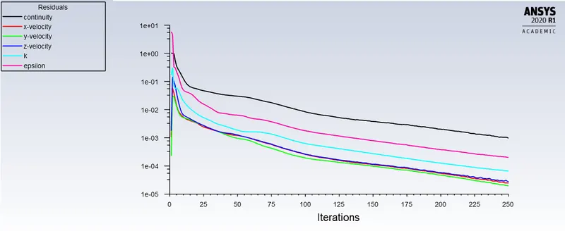
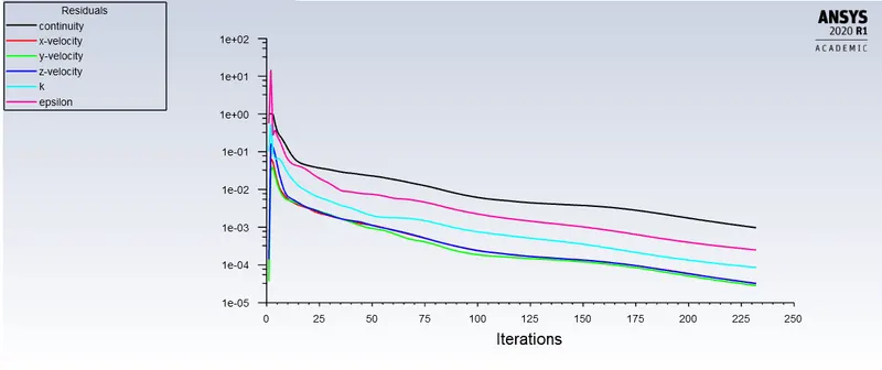
Case 2a (2m/s) Case 2b (5m/s)
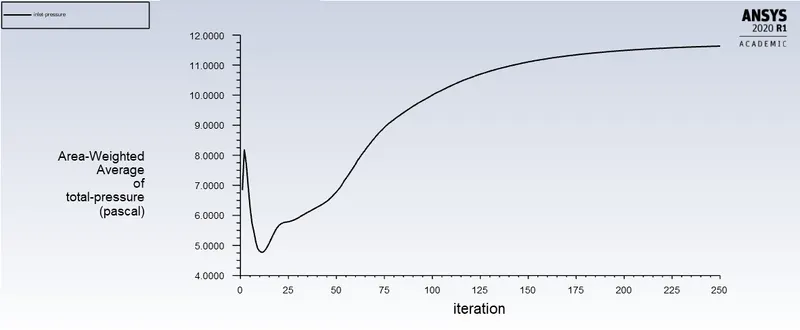
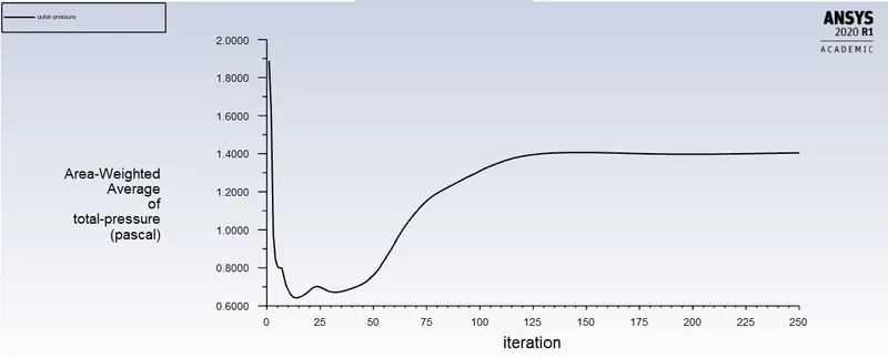
Case 2a (2m/s)inlet total pressure Case 2a (2m/s) outlet total pressure
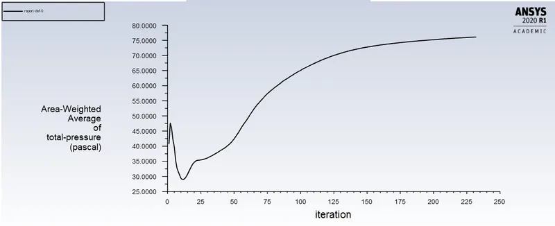
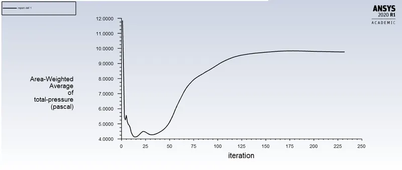
Case 2b (5m/s)inlet total pressure Case 2b (5m/s) outlet total pressure
Seperation/Collection efficiency
T/s = Nos. of Particles Trapped /Nos. of Particles Tracked.
| Velocity | Tracked | Escaped | Trapped | Incomplete | Seperation Efficiency |
| 2m/s | 190 | 30 | 160 | 0 | 85% |
| 5m/s | 190 | 30 | 160 | 0 | 85% |
Pressure Drop
Pressure Drop= Inlet Pressure - Outlet Pressure
| Velocity | Inlet Pressure(Pa) | Outlet Pressure(Pa) | Pressure Drop(Pa) |
| 2m/s | 11.5 | 1.4 | 10.1 |
| 5m/s | 70 | 9.5 | 70.5 |
CONCLUSION:
In this way, we have studied the effect of particle size, fluid velocity, and particle velocity on separation efficiency and pressure drop of the given cyclone separator.
- From the CASE-1 study, we can observe that the Cyclone efficiency has marginally increased as we increase particle size while keeping fluid and particle velocity constant at 3 m/sec.
- Since the velocity is 3m/sec for all particle sizes we simulate in CASE-1, the pressure drop remains constant
- Thus it is the important parameter for design consideration of cyclone separator.
- Cyclone efficiency generally increases with the increase in particle size, inlet duct velocity.
- The efficiency of a cyclone collector is related to the pressure drop across the collector.
- This is an indirect measure of the energy required to move the gas through the system.
- The pressure drop is a function of the inlet velocity and cyclone diameter as we can observe in CASE-2.
Empirical methods used for cyclone seperator efficiency:-
Laminar Flow Approach
The collection efficiency of single-particle size can be determined by a semiempirical approach, developed by Lapple (1951), in which the gas flow is considered laminar.
Assuming Laminar Flow the fractional collection efficiency is defined as ri= nNpd2V9µW =nNpd2Q9µHW2
where n is the fractional efficiency, N is the effective number of turns,p is the particle density,d is the particle diameter, V is the gas velocity,µis the gas viscosity, Q is the
volumetric flow rate of gas, and Hand W is defined as in Fig.8.8. This equation has one main deficiency in that it predicts that there is a finite value of dp beyond which the collection efficiency is always 100%, whereas experimental evidence shows that efficiency approaches 100% asymptotically with increasing particle diameter.
lozia and Leith
Any design method based on theory depends on the accurate prediction of efficiency and pressure drop. Dirgo and Leith(1985) developed an optimization program to investigate design changes that would improve cyclone separator design. Owing to the poor prediction by the efficiency and pressure drop theories used, substantial improvement in performance was not shown by pilot scale cyclones designed according to the program. Thus, efficiency and pressure drop theories with better predictive capabilities are needed. Subsequently,lozia and Leith (1990) developed an improved method to predict cyclone aerodynamic cut diameter, Aerodynamic cut diameter is the particle size collected with 50% efficiency. lozia and Leith claimed that their method works better than the theories of Lapple (1950), Leith and Licht (1972), and Dietz (1981).
Leith and Licht
The laminar flow model has limitations in that the gas flow in the cyclone is neither laminar nor fully turbulent; therefore, other models have been developed. A theory developed by Leith and Licht has proved useful in practical cyclone design. In their model, cyclone collection efficiency is given by
n(D1)=1-exp(-MDN)
where
N=1/(n+1)
n=1-(0.67D10.14)(T283)0.3
and
M=2[KQD13p(n+1)18µ]N/2
where 07 is the cyclone diameter in meters, T is the gas temperature in Kelvin,D is the particle diameter in centimeters,p is the particle density in g/cm3, Q is the volumetric flow rate in m3/s,µis the gas viscosity in g/cm-s and K is a geometric configuration parameter that depends only on the relative dimensions of the unit.
Pressure Drop Empirical Model.
Pressure drop is an important operating parameter because increased pressure drop results in higher operating costs. Higher cyclone efficiencies typically come with higher pressure drop; therefore,a compromise must be made between collection efficiency and pressure drop. Often,a cyclone must be designed around a given system pressure drop. There are several pressure drop equations inthe literature but most have not been found to be more accurate than the equation developed by Lapple:
P=12pgVg2Hv
where P is the pressure drop (Pa), p the gas density (kg/m3), V9 the gas velocity (m/s) and Hv the number of velocity heads defined by
Hv=KHWDe2
where H, W, and De are defined and K is an empirical constant with a value of 16 for a tangential inlet cyclone and 7.5 for one with an inlet vane.