Simulating Cyclone separator with Discrete Phase Modelling
Objective:
1. To know any four empirical models used for cyclone separator efficiency.
2. To Perform an analysis and to calculate pressure drop & separation efficiency of the cyclone separator model by varying the particle diameter and particle velocity individually.
Cyclone separator:
Cyclonic separation is a means of separating different liquid phases (different liquid densities), or, separating particles from a gas stream. Cyclone separators often form part of a pre-cleaning stage prior to a gas or liquid being discharged. This article focuses on the gas cyclone separator.
A cyclone separator has several colloquial names. These names include ‘dust separator’, ‘dust collector’, ‘dust extractor’, ‘cyclone extractor’ and ‘cyclone separator’. Generally, smaller units are referred to as ‘dust’ separators or extractors, whilst large scale industrial separators are referred to as ‘cyclone separators’.
Gas cyclone separators are grouped into two main categories, reverse-flow and axial-flow.
In this project we use a reverse flow cyclone separator because this type of separator is the most common in use today.
Reverse flow cyclone separators are cone shaped. Gas enters the top of the separator body, flows downwards, then flows back upwards and is discharged.
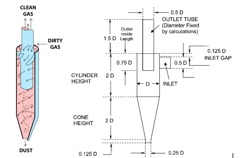
Formulae:
Pressure drop:
DR = Ra Inlet – Ra Outlet-1
Where:
DR = Cyclone Pressure Drop
Ra = Absolute Pressure
Separation efficiency:

Four empirical models used for cyclone separator efficiency
- IOZIA AND LEITH MODEL
Iozia and Leith (1990) logistic model is a modified version of Barth (1956) model which is developed based on force balance. The model assumes that a particle carried by the vortex endures the influence of two forces: a centrifugal force, Z, and flow resistance, W. Core length, zc, and core diameter, dc, are given as: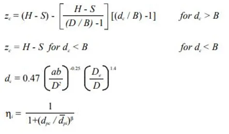
where dpc is 50% cut size given by Barth.
- LI AND WANG MODEL
This includes particle bounce or re-entrainment and turbulent diffusion at the cyclone wall. Li and Wang's model was developed based on the following assumptions:
1. The radial particle velocity and the radial concentration profile are not constant, for uncollected particles within the cyclones.
2. Boundary conditions with the consideration of turbulent diffusion coefficient and particle bounce re-entrainment on the cyclone wall are:
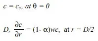
The Tangential velocity is related to the cyclone by, URn = constant
The concentration distribution in a cyclone is given as:
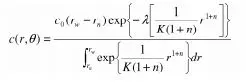
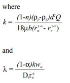
The resultant expression of the collection efficiency for particle of my size is given as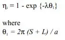
- KOCH AND LICHT MODEL
This Model recognizes the inherently turbulent nature of cyclones and the distribution of gas residence times within the cyclone. It describes particle motion in the entry and the collection regions with some assumptions,
1. The tangential velocity of particles is equal to the tangential velocity of the gas flow i.e. 'no slip' in tangential direction between the particle and the gas.
2. The tangential velocity is related to the radius of the cyclone by UR^n = constant
A force balance and the equation on this particles collection yield the grade efficiency,
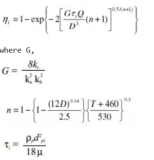
G is a factor related to the configuration of the cyclone, n is related to the vortex and τ is the relaxation term. - LAPPLE MODEL
It is a 1951 model developed by LAPPLE assuming that a particle entering a cyclone is evenly distributed along with the inlet opening. It is based on Force Balance without considering the flow resistance. In this model, the particle that travels from inlet half-width to the wall in the Cyclone is collected with 50% efficiency.
Efficiency,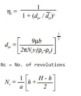
Geometry: Cyclone seperator model has been imported into space claim and the fluid volume is extracted
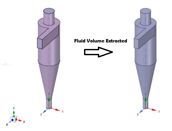
Note: After the extraction of fluid volume, the original body is suppressed for physics.
Meshing: Tetrahedron mesh with 10mm size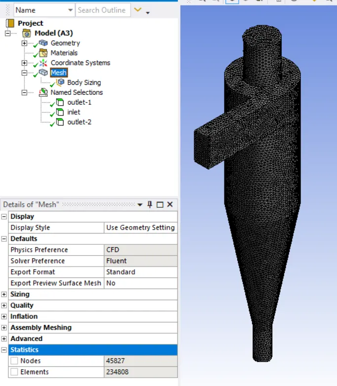
Setup & Solution:
Solver : Pressure based
Time : Steady
Check gravity in -Y direction
Turbulence model : K-epsilon – RNG – Swirl dominated flow
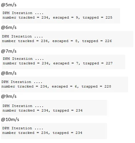
Setting up DPM(Discrete Phase Model) and setting up injection
in case1: X- velocity – 3m/s
Dia – Set as parameter (1E-06 to 10E-06)
in case2: X- velocity – Set as parameter (1m/s – 5m/s)
Dia – 5E-06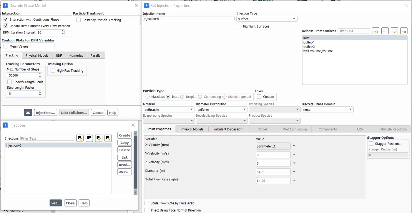
Boundary condition: Inlet DPM – Reflect
outlet-1 DPM – Escape
outlet-2 DPM – Trap
Inlet velocity – in case1: X- velocity – 3m/s
in case2: X- velocity – Set as parameter (1m/s – 5m/s)
Method: Simple
Initialization: Standard
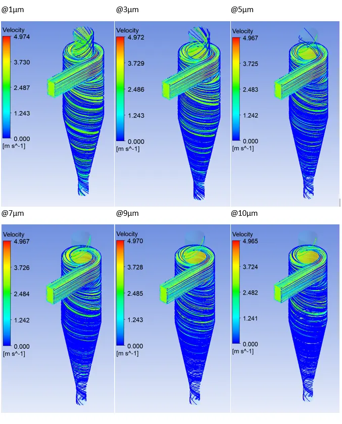
Case-1:
Iterations: 800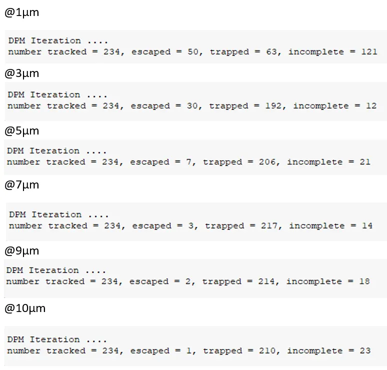

Velocity:
Pressure: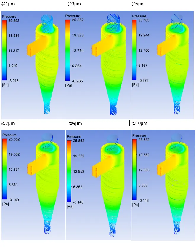
Pressure drop = 25.852 – 0.149 = 25.703pa
Anthracite Particle Time: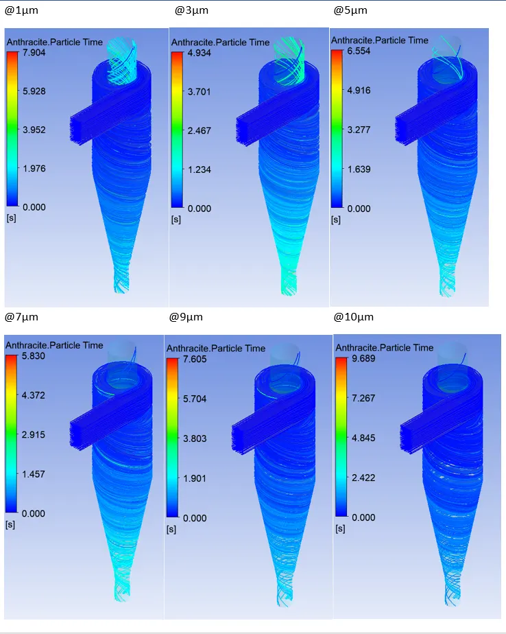
Case-2:
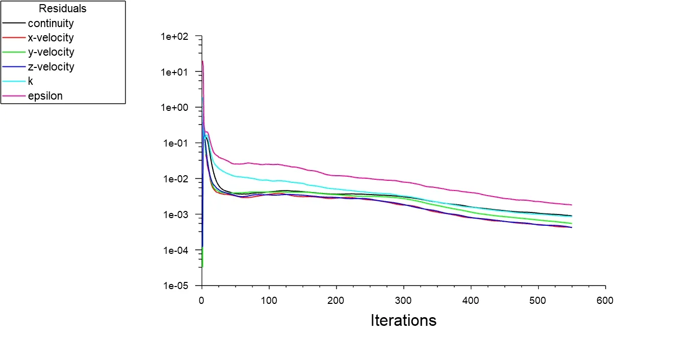
Iterations: 550
Velocity: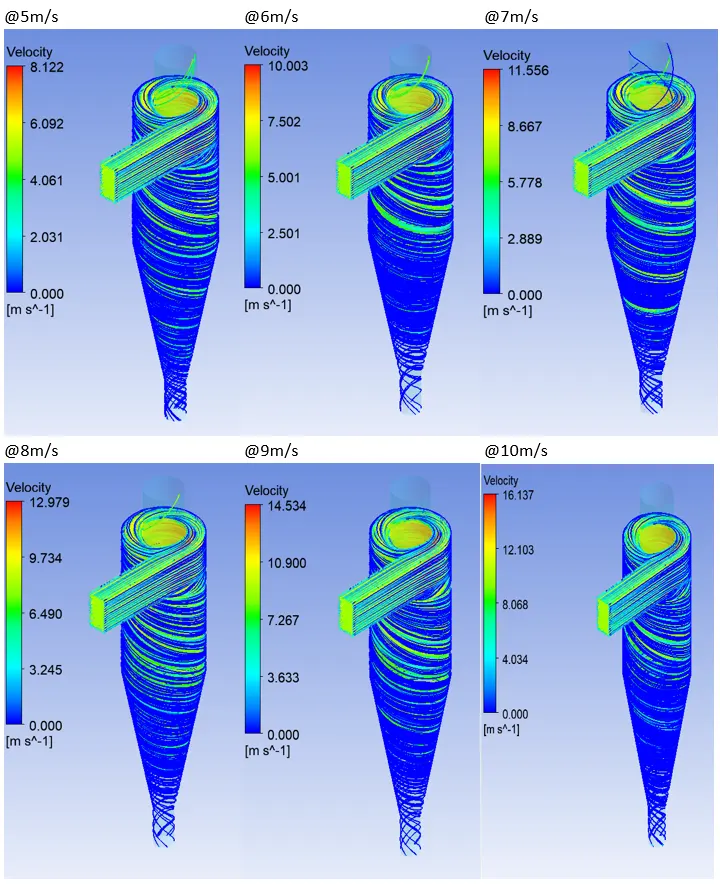
Pressure: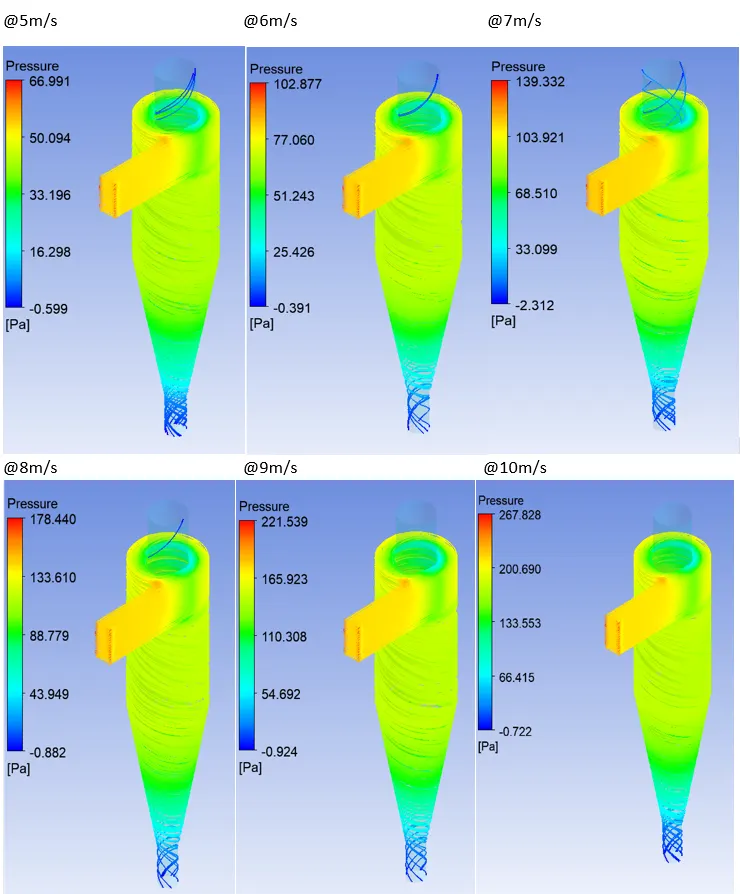
Anthracite Particle Time: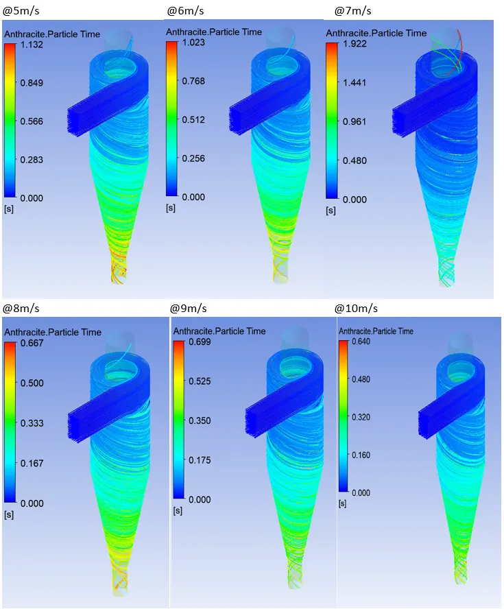
Conclusion:
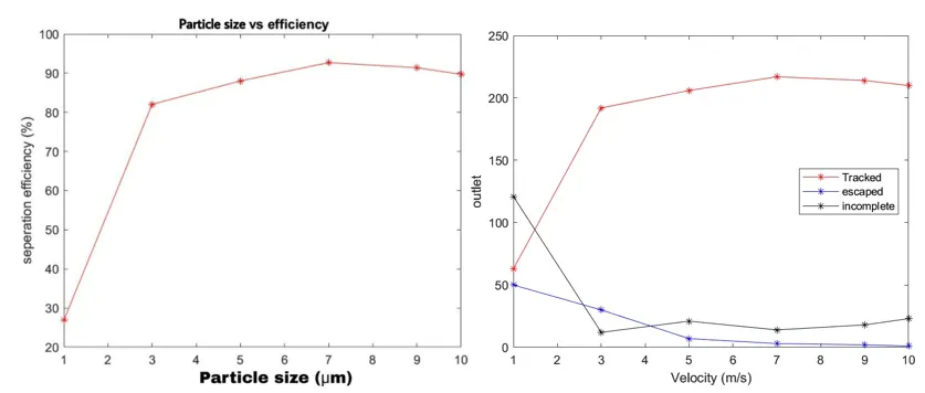
1. Particle size is a large design consideration effecting a separator’s efficiency. Larger particles can be more easily separated than smaller particles. A reduction in particle size will give a corresponding reduction in efficiency.
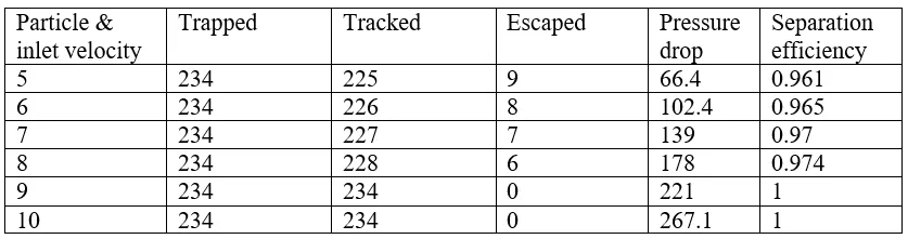
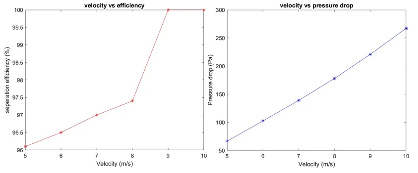
2. As the veelocity increased, seperation efficiency also increased.
3. There is an increase in the pressure drop in the system with the increase in inlet velocity.