CROSS CAR BEAM ASSEMBLY USING ANSA V20.1.4
OBJECTIVE:
The main aim of this project is,
- To mesh the cross-car beam parts as per the quality criteria shown below.
- To provide necessary connections.
- To assign thickness.
QUALITY CRITERIA:
|
S.No |
Quality Criteria |
Value |
|
1 |
Target/Average length |
5 |
|
2 |
Minimum Length |
3 |
|
3 |
Maximum Length |
7 |
|
4 |
Aspect |
3 |
|
5 |
Warpage |
15 |
|
6 |
Skewness |
45 |
|
7 |
Jacobian |
0.7 |
|
8 |
Minimum Quad Angle |
45 |
|
9 |
Maximum Quad Angle |
135 |
|
10 |
Minimum Tria Angle |
30 |
|
11 |
Maximum Tria Angle |
120 |
|
10 |
Tria Percentage |
15 |
PROCEDURE:
GEOMETRY CLEAN UP AND MIDSURFACE EXTRACTION:
- Imported the given .iges file in the ANSA work page.
- In order to view the model geometry clearly, the perimeter length of 1mm is applied to the model using the mesh module --> perimeter--> length option.
- Checked for orientation i.e. the upper part of the model should be in gray color meaning positive and the lower part in yellow color meaning negative.
- The issues with orientation are cleared using the topo module-->faces-->topo.
- The model is then subjected to a geometry checkup to check any free edges between the models, duplicate surface, irrelevant CONS using the option tools--> checks-->geometry.
- The geometrical errors are fixed by using the Auto option and some are cleared manually.
- Since the thickness of the parts remains constant, extracted the mid surface using the topo module-->faces--> mid surface--> skin, while keeping the parent geometry not getting deleted.
- Geometry check-up is done and a property ID is created with their respective thickness.
- By default, ANSA creates a steel material ID, which is defined so that the material is assigned to the model.
- The surfaces are split accordingly to attain good mesh flow and to avoid element failures using mesh module--> macros-->cut option.
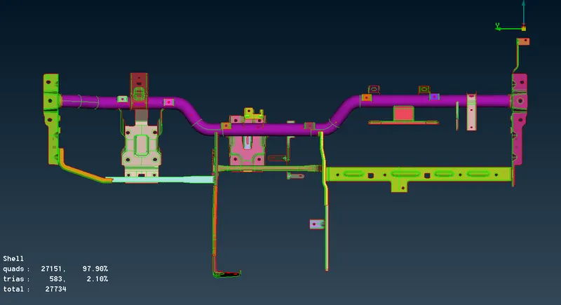
- 1.Mid-surface
MESH GENERATION:
- The Quality criteria are applied to the model using utilities--> Quality criteria as shown below,
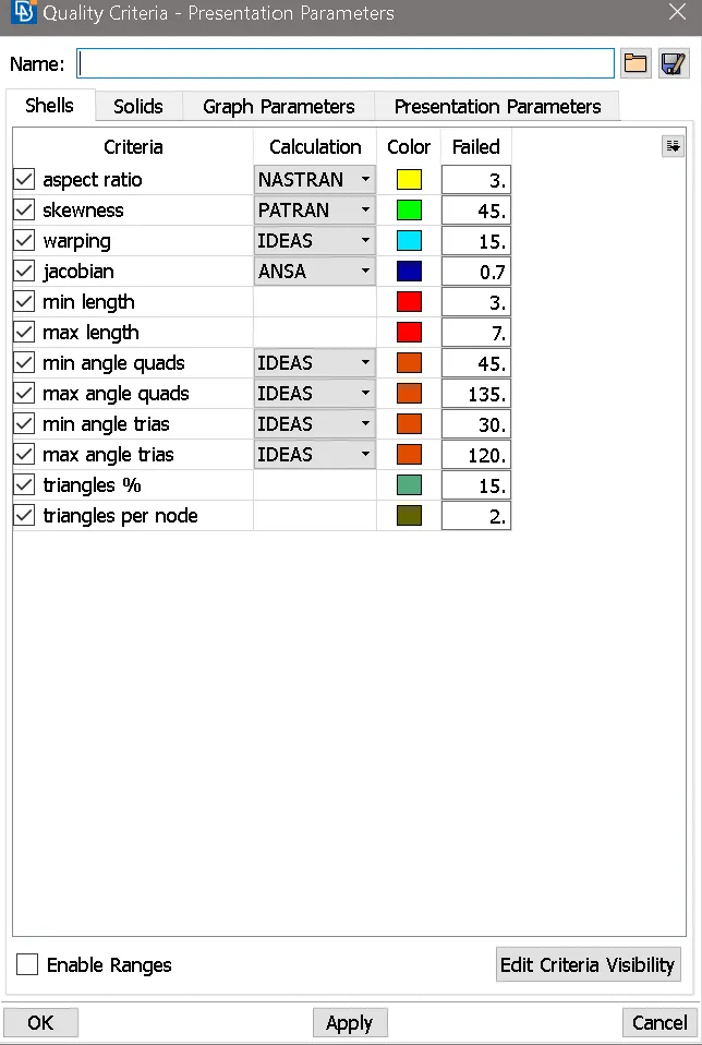
- 2.Quality Criteria
- Mesh parameters are applied as shown below, using utilities--> mesh parameter.
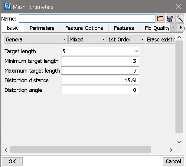
- 3.Mesh Parameter
- The perimeter elemental length is applied to the model using the mesh module --> perimeter--> length option.
- The split surfaces are meshed one by one using mesh module--> mesh generation--> Best option.
- During meshing the opposite trias, back to back trias, tias present at the edges, rotational quads can be removed using shell mesh--> reconstruct option.
- Trias present at edges, fillet areas, pattern formation, opposite trias can be avoided using split, swap, reconstruct, edge2 perimeter, Num +/- options.
- The elements which fail for quality can be viewed by using the Draw mode toolbar --> hidden option and corrections are done for the elements which fail for quality.
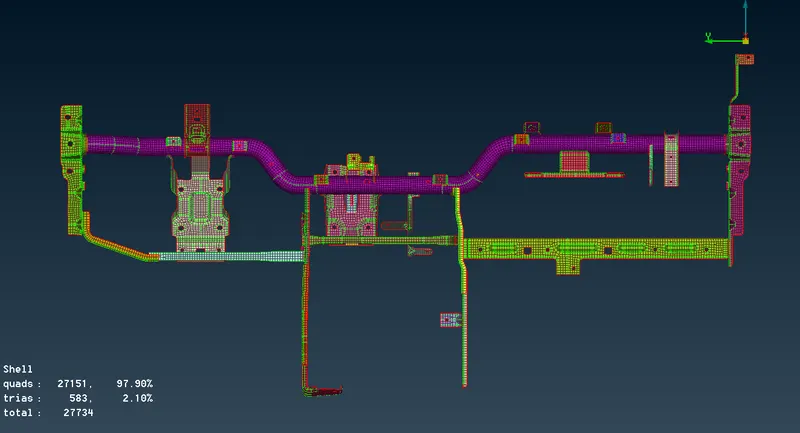
- 4.Meshed Model
THICKNESS ASSIGNMENT:
- The thickness assigned to the model can be viewed using utilities--> quality criteria--> presentation parameters --> draw shell as solid.
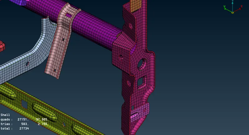
- 5.Thickened Model
CONNECTION:
- In order to connect the model with appropriate connections, here the bolt connections and seam weld connections are used.
Bolt connection:
- The bolts can be represented as rigids, it can be modeled with RBE2 elements.
- Here, the automatic blot representation method is used.
- To create that, a 3D point has to be created on the hole COG as shown below using Topo>points>on COG.
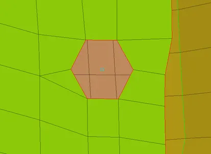
- 6.3d Point
- Then the 3D point has to be converted as blot representation using convert>3D point>bolts in assembly toolbar as shown below,
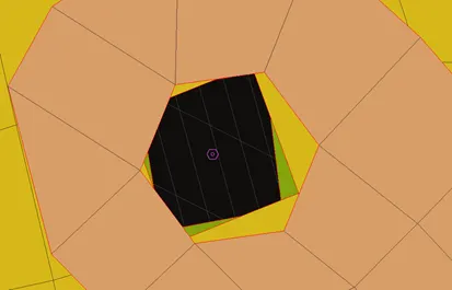
- 7.Bolt Representation
- Then the connection manager in the assembly toolbar is used and required inputs are provided for the bolt representation as shown below,
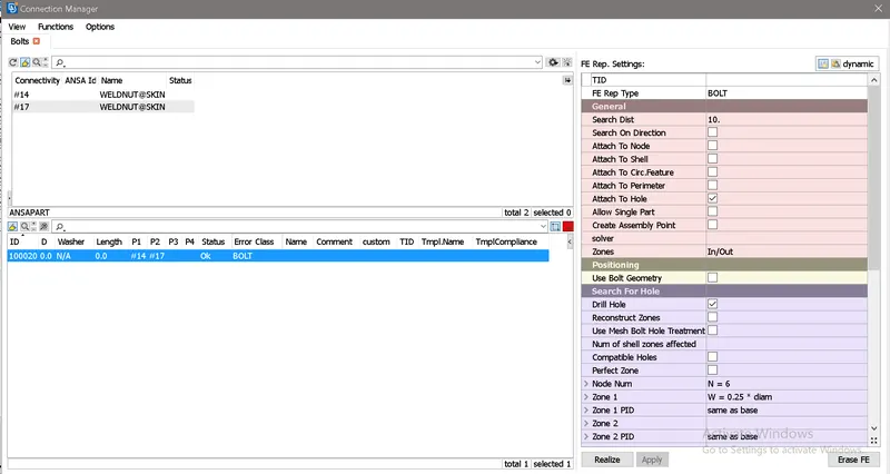
- 8.Control Manager for Bolt Creation
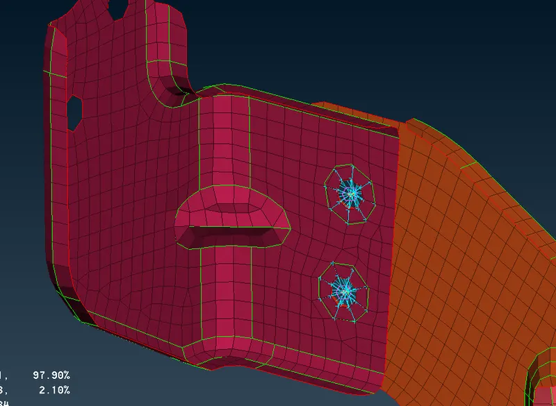
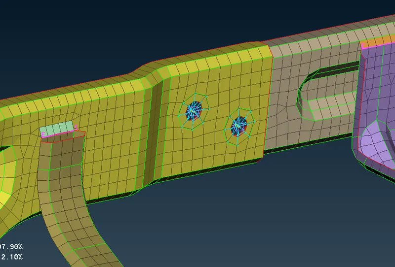
- 9.Bolt connections
Manual Bolt connection:
- Bolt connections are provided to the holes, where the parts are to be connected with bolts.
- That can be identified when the part holes are located next to each other.
- It is recommended that the bolt representation to the holes can be captured using a washer split of one layer.
- Generally, bolts can be represented as cluster RBE2 as well as two-node RBE2 connecting the master nodes of spider RBE2s.
- Generally, these bolt representations are done manually using Nastran deck>elements>RBE2.
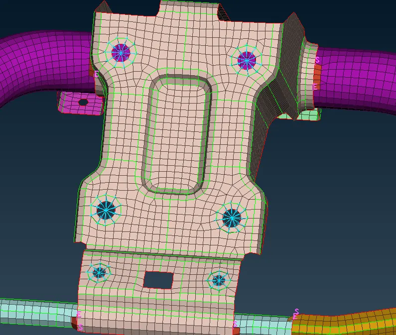
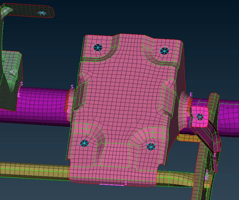
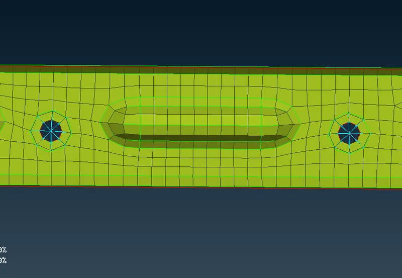
- 10.Manual Bolt Representations
Seam connection:
- Seam weld is used to connect the parts in continuous seam line.
- It provides more structural rigidity to the system.
- To generate seam weld, the seam data has to be obtained and then curve is created along the length to represent the seam length.
- Then the curve has to converted into seam line using the assembly toolbar convert>curves> seam line.
- Then the seam line can be realized using connection manager from assembly toolbar and inputs are provided as shown below,
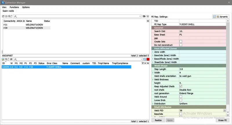
- 11.Control Manager for Seam Weld Connection-y-joint
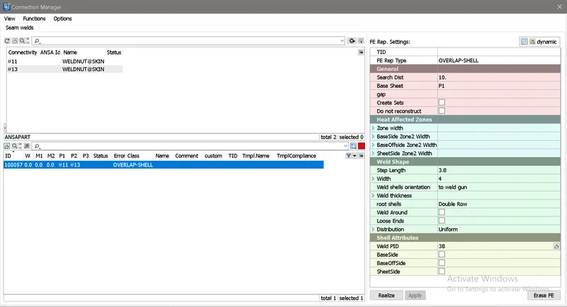
- 12. Control Manager for Seam Weld Connection-Overlap joint
- The seam weld representation as follows,
- Basically, if the parts are parallel to each other, then the FE rep type has to chosen as overlap shell.
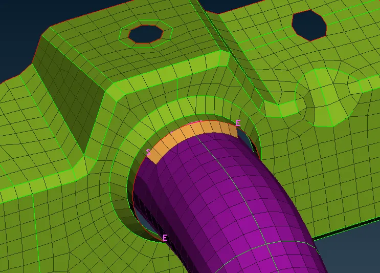
- 13.Seam Weld Representation for Parallel Parts
- If the parts are perpendicular to each other, then the FE rep type has to chosen as Y-joint shell.
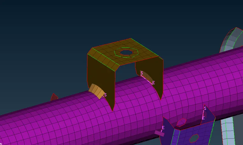
- 14.Seam Weld Representation for Perpendicular Parts
- Finally, save the file.
RESULT:
Hence,
- The cross-car beam model is meshed as per the quality criteria given.
- The appropriate connections are provided to the model.
- The thicknesses are assigned to the model.
LINK TO VIEW THE MODEL: