Creation of Multiple viewports, Scaling the drawing and setting in Template in AutoCad
PROBLEM :1
- AIM :
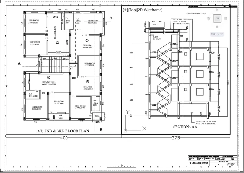
- Create a layout of the Plan and Section A of the project in Challenges 7, using the template Tutorial-mArch.dwt in a scale as given in the Figure. Use the MV command to create the viewport of the size as shown in Figure. Also, use the ATTEDIT command to edit the information in the title block. Use A1 size for the layout. Take a plot.
- PROCEDURE :
- click on the AutoCAD application
- type the QNEW command
- select the setting METRIC
- click on ADVANCED SETUP
- unit: DECIMAL precision 0
- angle: DECIMAL DEGREE
- angle measure: EAST
- then,
- angle direction: COUNTER CLOCKWISE
- PRESS: NEXT
- set area :
- length: 100
- width: 100
- press: Finished
- command: UN (for units )
- set DECIMAL precision 00
- unit: mm
- press: enter
- command: Z (for zoom )
- type a for all
- press: ENTER
- THE PLAN IS ALREADY DRAWN IN CHALLENGE NO 7
- THE FILE IS ALREADY SAVED IN AUTOCAD 2021 SOFTWARE
- COMMAND USED TO DRAW THE PLAN GIVEN BELOW :
- START: QSTART
- UNITS: UN
- LIMITS: LIMMAX
- ZOOM: Z
- OFFSET: O
- LINE: L
- RECTANGLE: REC
- TRIAM: TR
- DIMENSION: DIMLIN, DIMCONTINUE
- TEXT: MTEXT
- command: QOPEN
- select the file
- press: enter
- command: V (for view )
- then give the name o view as PLAN
- select the window v
- press: enter
- again,
- command: V (for view )
- give the view name as a SECTION AA
- Select the window
- press: enter
- command: LAYOUT
- type N (for now )
- give the name of the layout as a PLAN
- press: enter
- right click over the PLAN layout
- click on the page setup manager
- then, click on modify
- select the name of the printer as a
- DWG TO PDF. pc3
- then click on the paper size
- give the paper size as a
- ISO A1 (841.00 X 594.00 MM )
- Press: OK
- again right click oven layout name is a PLAN
- click on TEMPLETS
- select the templets name as Tutorial-mArch
- press: ok
- command: REC (for rectangle )
- select the start point
- click on DIMENSION
- Length: 400
- width: 445
- again,
- command: REC (for rectangle )
- give the starting point
- click on DIMENSION
- length: 375
- width: 445
- press: ENTER
- Take a command
- command: MS and
- command: MV
- select the first rectangle
- press: enter
- command: V (for view )
- click on PLAN Viewport and set it current
- press: OK
- again
- command: V (for view )
- select the viewport as SECTION AA
- Set it current
- select the scale 1: 50
- press: enter
- command: PAN
- already MS command is active
- select the pan command and properly pan the object in both two viewport
- then,
- select both viewports
- go to the properties
- and locked it
- command: PS
- press: enter
- Right-click over the layout
- page setup manager
- click on MODIFY
- click on the plot style table
- slect the monochrome.cub
- click on display plot style
- then click on ok
- command: ATTEDIT
- press: enter
- select the object as a templet
- and edit attributes
- press: enter
- Command: DIMLIN
- Give the dimension
- command: MTEXT
- write the required text
- press: ENTER
- RESULTS :
- COMMAND USED :
- START: QNEW
- UNITS: UN
- LIMITS: LIMMAX
- ZOOM: Z
- MV
- PS
- VIEW: V
- ATTEDIT
- RECTANGLE: REC
- DIMENSION DMLIN
- TEXT: MTEXT
PROBLEM NO: 2
AIM :
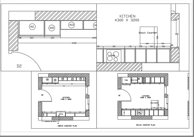
Create a layout of the Kitchen drawn in Challenge 9 as shown in Figure. Use the scale as shown in the Figure. Use an A4 Size page for the layout. Take a plot.
- PROCEDURE :
- click on the AutoCAD application
- type the QNEW command
- select the setting METRIC
- click on ADVANCED SETUP
- unit: DECIMAL precision 0
- angle: DECIMAL DEGREE
- angle measure: EAST
- then,
- angle direction: COUNTER CLOCKWISE
- PRESS: NEXT
- set area :
- length: 100
- width: 100
- press: Finished
- command: UN (for units )
- set DECIMAL precision 00
- unit: mm
- press: enter
- command: Z (for zoom )
- type a for all
- press: ENTER
PROCEDURE OF VIEWPORT
-
- command: QPEN
- select the file
- and open it
- command: layout
- give the name of the layout as a KITCHEN LAYOUT
- press: ENTER
- right click over the kitchen layout
- click on PAGE SETUP
- CLICK ON MODIFY
- give the printer name
- also give the size of paper
- all shown below
- command: LAYOUT
- TYPE 4
- PRESS: enter
- the sheet is divided into 4 parts
- press: enter
- command: v (for view )
- give the view name as ABOVE KITCHEN LAYOUT
- select the widow
- click on Ok
- again the command: V (FOR VIEW )
- give the name of the view as BELOW KITCHEN LAYOUT
- press: ENTER
- go to the layout
- command: MV
- click on the first rectangle
- command: MS
- by using the zoom and pan commands placed the plan in a rectangle
- then click on another rectangle
- placed the object in a proper way
- in this way placed all object
- then, select all viewport
- to the properties
- and locked it
- command: MTEXT
- and write the text
- press: enter
- RESULTS :
- COMMAND USED
- VIEW: V
- PEGESETUP
- MS
- PS
- TEXT: MTEXT
PROBLEM : 3
AIM :
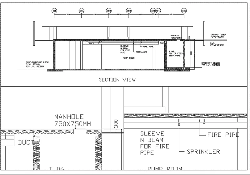
. Create a layout of the section created in Challenge 9.
Use the scale as mentioned in the Figure. Use the MV command to create multiple viewports. Take a plot.
- PROCEDURE :
- click on the AutoCAD application
- type the QNEW command
- select the setting METRIC
- click on ADVANCED SETUP
- unit: DECIMAL precision 0
- angle: DECIMAL DEGREE
- angle measure: EAST
- then,
- angle direction: COUNTER CLOCKWISE
- PRESS: NEXT
- set area :
- length: 100
- width: 100
- press: Finished
- command: UN (for units )
- set DECIMAL precision 00
- unit: mm
- press: enter
- command: Z (for zoom )
- type a for all
- press: ENTER
PROCEDURE OF VIEWPORT
- THE PLAN IS ALREADY DRAWN IN CHALLENGE NO 9
- AND FILE IS ALREADY SAVED IN AUTOCAD SOFTWARE
- command: QNEW
- select the file
- and open it
- command: layout
- type N (for now )
- give the name of the layout is an industrial building
- press: enter
- right click on the layout
- click on page setup
- give the name of the printer
- also select the page type as shown below
- command: MV
- type 3
- then type A (for above )
- press: enter
- command: v (for view )
- click on NEW
- give the viewport name as ABOVE THE KITCHEN LAYOUT
- PRESS: ok
- again this process
- give the name as BELOW THE KITCHEN LAYOUT
- PRESS: OK
- go to the layout
- command: MV
- select the rectangle
- command: MS
- place the object by using the zoom and pan command
- again click on another rectangle
- and placed the object
- again the third rectangle
- and placed the object in a proper way
- command: PS
- PRESS: ENTER
- Select the all-view port
- go to the properties
- and locked it
- press: ENTER
- RESULTS :
- COMMAND USED :
- VIEW: V
- OPEN: QOPEN
- PAGE SETUP
- PAN : P
- ZOOM: Z
THANK YOU !!!!!!!!!!!!!!!!!!!!!!!!!!!!!!!!!!!!!!!!!!!!!