Creating Kitchen layout, Hatching of Architectural elements and sectional view of an Industrial Building in AutoCad
ANS.1.
AIM :
-
Create the layouts of the Kitchen and provide a hatches pattern as shown. Also, use blocks wherever required. Provide appropriate dimensions in the plan. Assume the size of doors, appliances, and others as per the standards.
- PROCEDURE :
- click on the AutoCAD application
- type the QNEW command
- select the setting METRIC
- click on ADVANCED SETUP
- unit: DECIMAL precision 0
- angle: DECIMAL DEGREE
- angle measure: EAST
- then,
- angle direction: COUNTER CLOCKWISE
- PRESS: NEXT
- set area :
- length: 100
- width: 100
- press: Finished
- command: UN (for units )
- set DECIMAL precision 00
- unit: mm
- press: enter
- command: Z (for zoom )
- type a for all
- press: ENTER
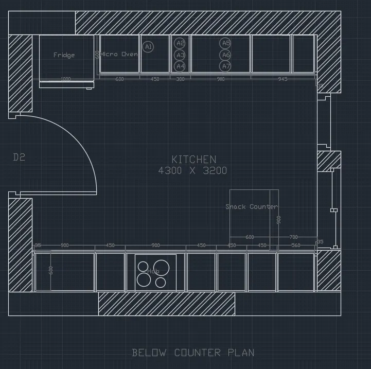
- BELOW IS THE COUNTER PLAN :
- command: XL
- mark the vertical and horizontal lines
- press: ENTER
- command offset
- give the offset distance of 230
- both for vertical and horizontal
- command :o
- give the distance 35,900,450,900,450,450,450,560,35,230
- give the vertical offset line the distance shown above
- command: offset
- give the set distance of 20 for each offset line
- command: offset
- distance 600
- give it by reference to horizontal lines
- command: TR (for trim )
- trim the extra lines
- press: ENTER
- command: offset
- distance 3660 from the reference of horizontal lines
- then
- using the offset command mark the internal offset line at a distance of 230
- command: offset
- mark a vertically set line
- distance is given below
- 50,1000,600,450,300,300,900,300,945,35,230
- press: enter
- command: offset
- and mark the vertical ofset line reference of each vertical ofset line at a distance of 20
- command: TR (for trim )
- trim the extra part
- press: enter
- command: c (FOR CIRCLE )
- mode 2 point circle
- draw a circle between two point
- command: REC (for rectangle )
- draw a hinge of the door
- press enter
- command: L (for a line )
- draw a line
- command: TR (for trim )
- trim the extra part
- press: ENTER
- give the hatch to the island
- press: enter
- command: H (for hatch )
- command: HATCH
- go to the hatch setting
- click on predefined
- select the hatch pattern ANSI32
- select the hatch colour COLOUR 253
- click on PICK POINT
- command: DIMLIN (for dimension )
- give the dimension
- command : DIMCONTINUE
- and give all dimension
- command: TEXT STYLE
- select the font Txt. shx.
- give a height is 50
- set current
- press: ENTER
- command MTEXT (for text )
- write all the text
- press: enter
- select all, the dimension
- give the dimension line colour is red
- and text colour is yellow
- press: enter
- again select all the text
- go to the BY LAYER
- select the layer colour is cyan
- press: enter
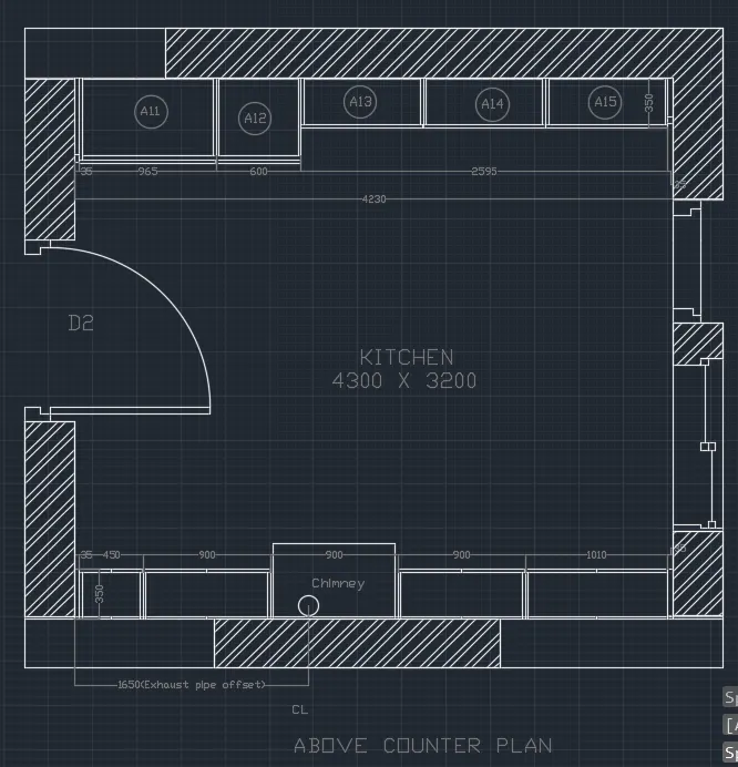
2. ABOVE THE COUNTER PLAN
PROCEDURE :
- Command: XL
- mark a vertical and horizontal line
- press: enter
- command offset
- give the offset distance of 230
- again command of the set
- distance 4460 and then give the offset distance 230
- press: enter
- command: TR (for trim )
- trim the extra lines
- command: offset
- distance:230 mark this line by taking a horizontal line as a reference
- command: offset
- distance 3430 and then give 230 of the set line
- press: enter
- command: TR (for trim )
- trim the extra lines
- command :o (for offset )
- distance 35,450,900, 900,900,1010,35
- mark the vertical ofset line distance shown above
- command: offset
- distance 20 gives the offset line of each vertical offset line
- command: TR (for trim )
- trim the extra lines
- command: offset
- distance 350 then 20 mark these lines by reference of horizontal lines
- command: circle
- take the centre point of the circle 1650 distance from the left side
- as shown in fig
- command :o (FOR Offset )
- distance 35,965,600,2595,35
- from upward
- press enter
- command: O (for offset )
- distance 20 for each offset line
- command: TR (for trim )
- trim the extra lines
- command: REC (for rectangle )
- draw the rectangle for the hinge of the door
- then,
- command: C (for circle )
- select the 2-point circle mode
- draw the circle in between the hinges of the door
- command: TR (for trim )
- trim the extra lines
- in this way the door is ready
- command: H (for hatch )
- go to the hatch seating
- select the PREDEFINED type
- select hatch pattern SOLID
- select the colour of the hatch COLOUR 253
- CLICK ON PICK POINT
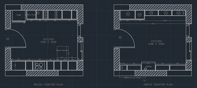
- RESULTS :
- COMMAND USED :
- START: NEW
- UNITS: UN
- LIMIT: LIMMAX
- ZOOM: Z
- COMMAND: XL
- OFFSET: O
- TRIM: TR
- HATCH: H
- TEXT: MTEXT
- DIMENSION: DIMLIN
ANS.2.
- AIM
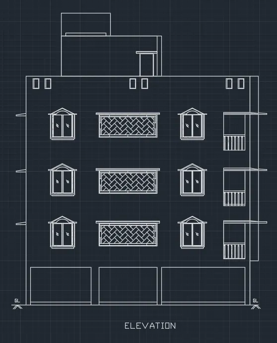
- Create the elevation of the plan created in Challenge 7 and apply proper hatch in the walls, doors, windows, and other architectural elements. Refer to the dimensions in the Plans and sections in Challenge 7.
- PROCEDURE :
- click on the AutoCAD application
- start the application
- type the QNEW command
- select the METRIC
- then click on the wizard and ADVANCED SETTING
- Set unit: decimal precision 0
- angle : decimal presicion 0
- then, angle measure: EAST and press NEXT
- angle direction: counterclockwise
- press: nest
- set area :
- length: 100
- width:100
- press: ENTER
- Command: UN (for units )
- set units in decimal
- and mm
- press: ENTER
- COMMAND: Z (for oom )
- type A (for all )
- press: ENTER
- command: REC (For rectangle )
- select the start point
- click on DIMENSION
- length: 5
- width 10
- press: enter
- command: MI (for mirror )
- select the object
- press: enter
- select the base point
- and mirror it
- command: offset
- give the offset distance
- and give the offset to the rectangle
- command: L (for line
- and draw the remaining part
- command: circle
- select two-point mode
- draw the circle in between two point
- command: TR (for trim )
- trim the extra part
- Press: enter
- command: REC (for rectangle )
- select the start point
- click on DIMENSION
- length:24
- width: 10
- press: ENTER
- command: H (for hatch )
- select the predefined type
- select the hatch pattern as shown below
- select the pick point
- also select the base point
- give the hatch
- press: ENTER
- Command: AR (for array )
- select all object
- select the RECTANGLE mode
- and array it
- press: ENTER
- command: REC (for rectangle )
- and draw the rectangle
- command :x (explode )
- select object
- press: ENTER
- command :O (for offset )
- give the offset distance
- click on the bottom horizontal line of the large rectangle
- and give a set
- command: L (for line )
- by using the line command draw the remaining part
- command: TR (for trim )
- trim the extra line
- press: enter
- now elevation is readily shown below
- command: H (for hatch )
- click on SETTING in the command section
- click on GRIDENT
- SELECT the pattern
- as shown below
- select the PICK-UP POINT
- also select the base point
- hatch the object
- press: ENTER
- RESULTS :
- COMMAND USED :
- START: NEW
- UNITS: UN
- LIMITS: LIMMAX
- ZOOM: Z
- RECTANGLE: REC
- LINE :L
- TRIM: TR
- OFFSET: O
- HATCH: H
- TEXT: MTEXT
ANS.3.
AIM :
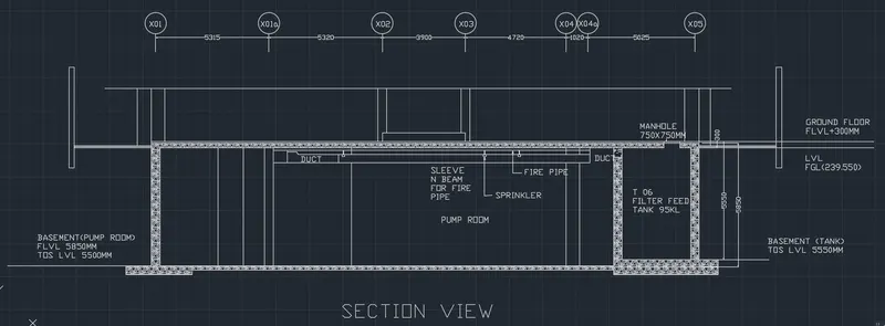
- create the section view of an industrial building as shown in the figure. provide appropriate dimensions wherever required. also, provide annotations to the drawing
- PROCEDURE :
- click on the AutoCAD application
- type QNEW in the command section
- click on advance setup
- unit decimal precision 0
- angle decimal precision 0
- angle measure: EAST
- set angle direction counterclockwise
- press: NEXT
- Set the area
- length:100
- width:100
- press: OK
- command: UN (for units )
- give the units in decimal
- and mm
- press: ENTER
- command: Z (FOR zoom )
- type A in the command section
- press: ENTER
- command: REC (for rectangle )
- select the start point
- click on DIMENSION
- length: 25300
- width: 5850
- press: enter
- command: O (for offset )
- give the offset distance of 300
- press: enter
- command: X (for explode )
- select the object
- press: enter
- command :L (for line )
- by using the line command draw the remaining part
- press: enter
- command: MTEXT (for text )
- write the text over the section plan
- press: enter
- then go to the ANNOTATION tab
- click on multileader
- click on CONTENT
- selct the MTEXT option
- select 2 points for the leader
- as shown in fig
- press: enter
- command: H (for hatch )
- click on SEATING in the command section
- select the pattern as shown below
- select the pick point
- press: enter
- go to the object
- and give the hatch
- after that press: enter COMMAND: DIMLIN (for dimension )
- give the dimension command: DIMCONTINUE And give all dimension
- press: enter
- RESULTS :
- COMMAND USED :
- START: QNEW
- UNITS: UN
- LIMETS LMMAX
- ZOOM: Z
- RECTANGLE: REC
- LINE: L
- OFFSET: O
- HATCH: H
- QLADER
- TEXT: MTEXT
- DIMENSION: DIMLIN, DIMCONTINUE
THANK YOU!!!!!!!!!!!!!!!!!!!!!!!!!!!!!!!!!!!!