Creation of Multiple viewports, Scaling the drawing and setting in Template in AutoCad
Q1.
Aim: Creating a layout of the Plan and Section A of the project in Challenges 7 and using the template type Tutorial-mArch.dwt in a scale as given in the Figure.
Introduction: Layout is a option in the autocad that drawing can be changed into the sheet of paper with a suitable scale. And using the MV command for viewport. We can port the diagram into number of ports. We create a layout with a different sizes of paper like A4,A3,A2 etc., We can save view of drawing line plan,elevation and etc.,
Procedure:
First opening the autocad and opening the drawing of the challenge 7
Type V in the command line select the option define window
Now the view plan and section AA is saved with a name plan and section A
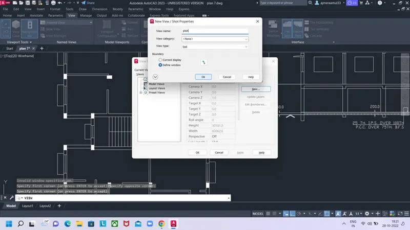
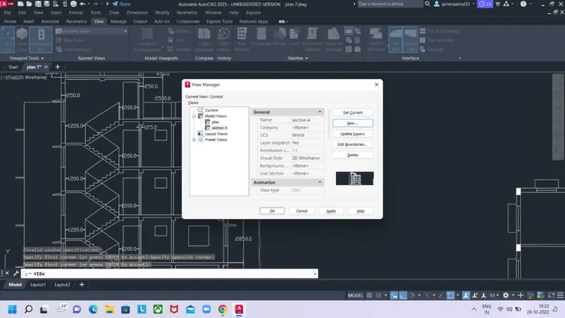
Now type LAYOUT in the command line
And select the option TEMPLATE
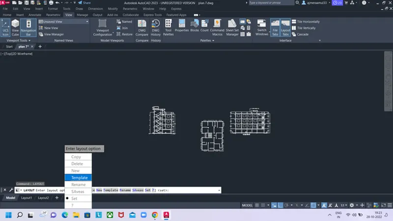
After selecting option template select the type of template called Tutorial-mArch
It will create the new layout
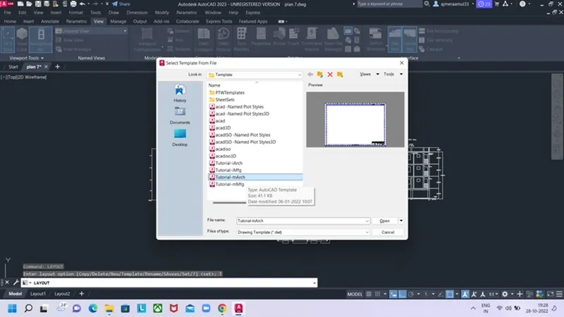
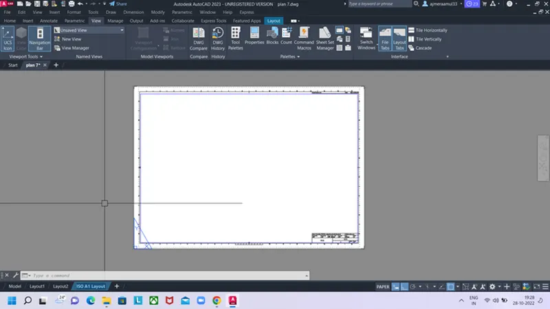
Now type MV in the command line
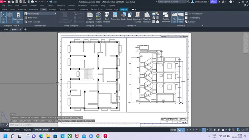
And create a 2 rectangles in the sheet
And import the plan in one rectangle and section A in other rectangle by command MS.
MS commands means we can edit the drawing in the view port and we can zoom in and zoom out in the view port
PS commands means we zoom in and out and we edit page
Now type ATTEDIT for editing the attribute
And select the attribute in the drawing
As the template a type of block with attributes
The attributes are edited as below
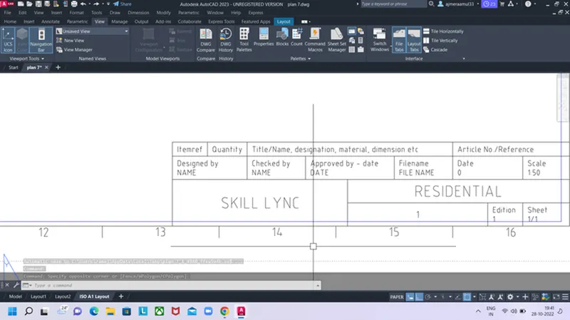
Now the sheet is ready for print
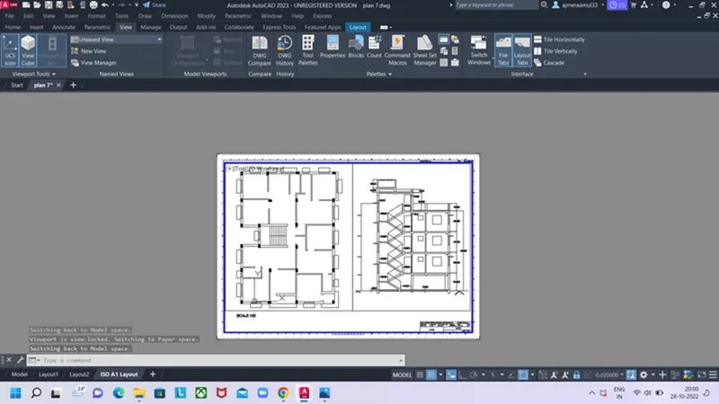
Now right click on the layout which we created
Select the plot option
Select the options as we want and press ok
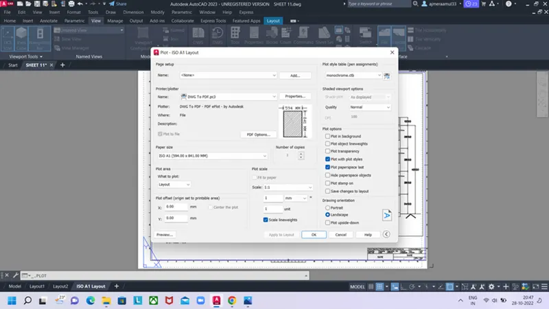
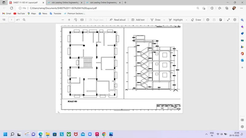
Now the drawing is converted into pdf file and save in our files
Result:
Q2.
Aim: Creating a layout of the Kitchen drawn of a Challenge 9 in the paper size of A4 and ploting the drawing into pdf.
Introduction: We can make pdf file of the drawing and print in the different size of paper size. MS commands means we can edit the drawing in the view port and we can zoom in and zoom out in the view port. PS commands means we zoom in and out and we edit page
Procedure:
Opening the software autocad
And opening the saved kitchen drawing document of a challenge 9
Creating the views of a drawing as shown in the question
The views are named as v1,v2,v3 and v4.
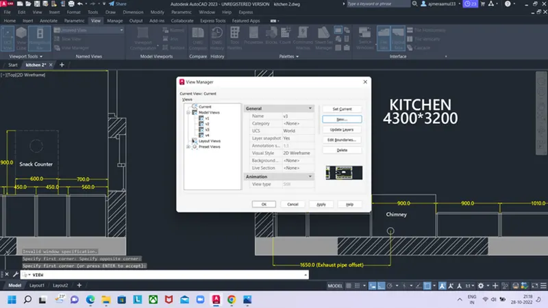
After creating the views of the drawing
Right click on the layout 2 and select the option page setup
Click on the new and name the layout
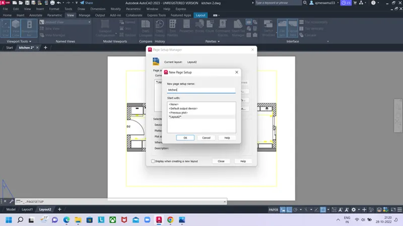
After named the layout press ok
And select the option modify
Select the name and paper size of A4 297.00*210.00mm
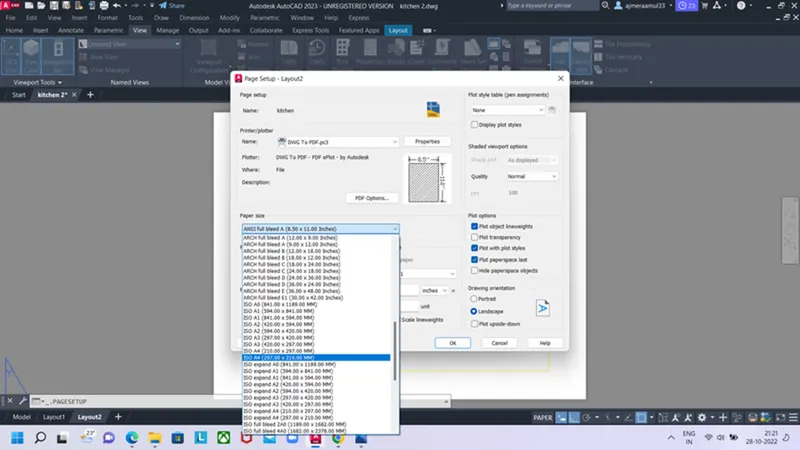
And modify the other settings as per we want
And see preview of the setting and press ok
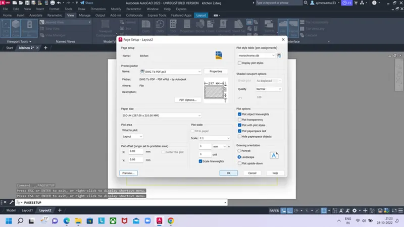
Now the A4 paper with a size of 297*210mm is ready
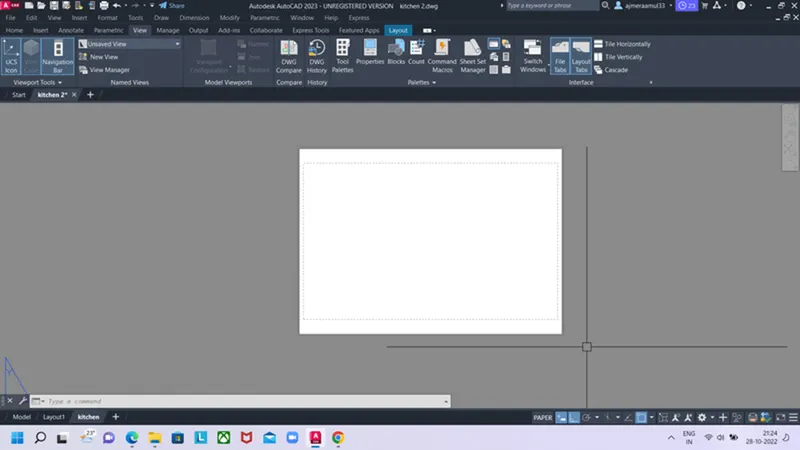
Now Type MV in the command line to activate the multipleview
Draw 4 rectangles called as 4 viewports
Now type MS in the command line and select views that we created for challenge line drawing
MS commands means we can edit the drawing in the view port and we can zoom in and zoom out in the view port
PS commands means we zoom in and out and we edit page
After selecting view types the sheet shows as below
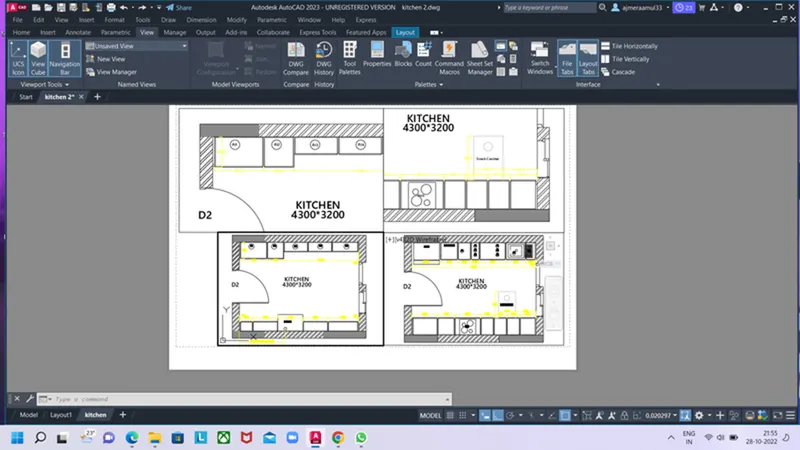
Now again right click on the layout which we named as new layout
And select the option of plot
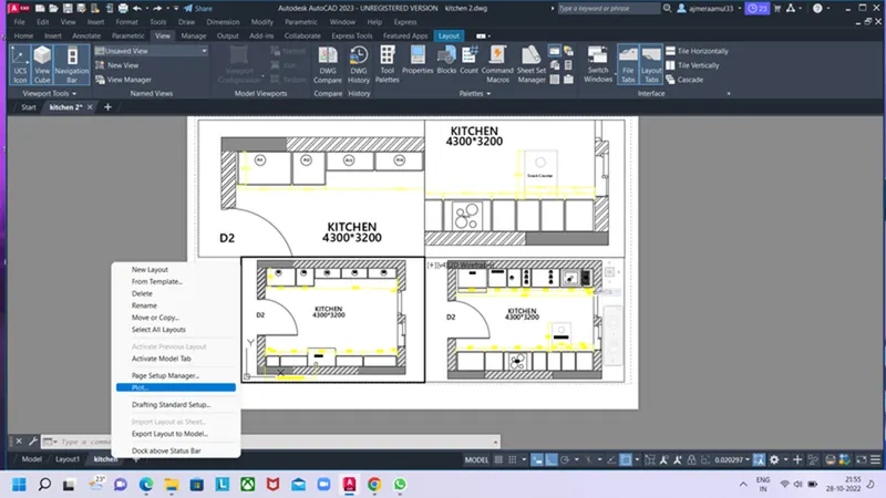
Select the such setting and press ok
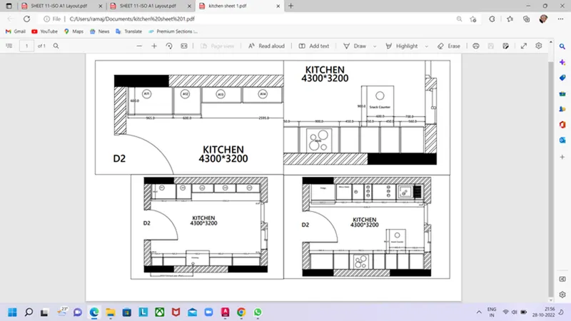
Now the drawing is converted into pdf file
Result:
Q3.
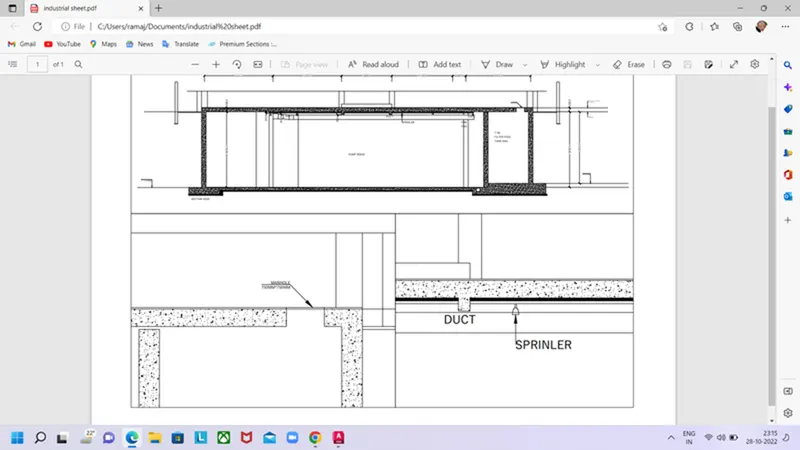
Aim: Creating a layout of the industrial section created in Challenges 9. Using MV command creating the multiple viewports of indutrial section plan
Introduction: Using such type of commands like MULTIPLEVIEW,MODELSPACE(MS),PAPERSPACE(PS),LAYOUT command for creating the layouts
Procedure:
Opening the software autocad
And opening the saved industrial section drawing document of a challenge 9
Creating the views of a drawing as shown in the question
The views are named as v1,v2, and v3
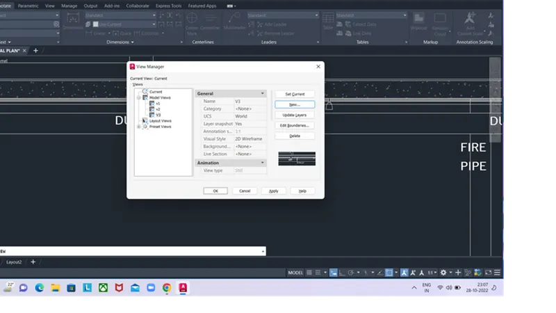
After creating the views of the drawing
Right click on the layout 2 and select the option page setup
Click on the new and name the layout
Name the layout as industrial section
After naming the layout
Right click on the layout in which layout we gonna creating a drawing into sheet
Select the option called page setup
And set the options as we want
Select the paper size
Press ok
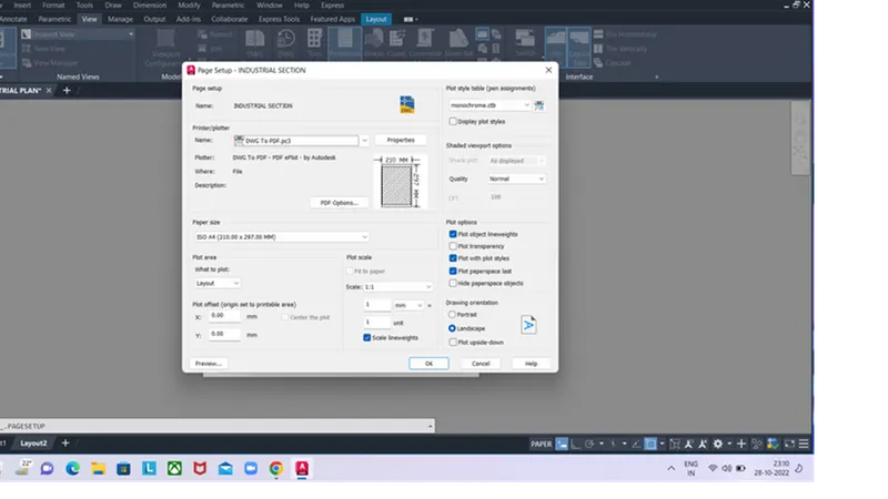
After pressing ok we get a paper sheet as we required
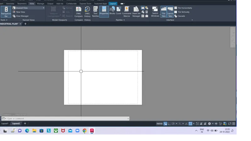
Now type MV in the command line to activate the tool multiple view
And draw a 3 rectangles as a 3 viewport
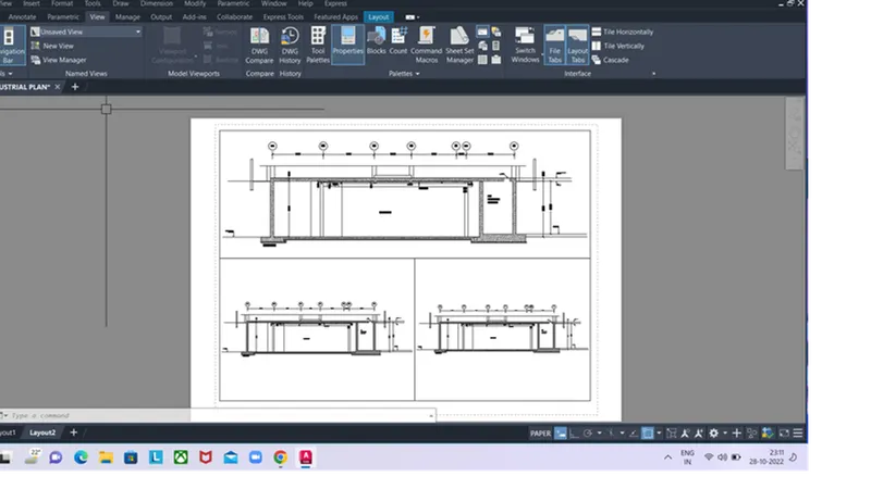
Select the viewports by MS command and select the views that we created
We get the following result after selecting the view of a drawing
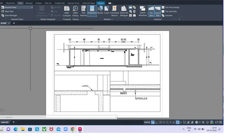
Now again right click on the layout which we named as new layout
And select the option of plot
Set the options as we required
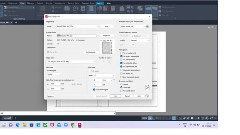
Now the pdf file is ready for the industrial section
Result: