Creation of Multiple viewports, Scaling the drawing and setting in Template in AutoCad
Q 1. Make layout of the Plan and Section A of the project in Challenges 7, utilizing the template Tutorial-mArch.dwt in a scale as provided in the Picture. Use the MV command to make the view port of the size as given in Picture. Also, utilize ATTEDIT command to edit the information in the title block. Use A1 size for the layout. Take a plot.
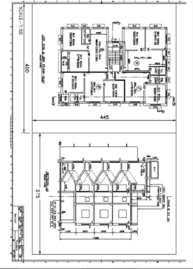
AIM:
- To make layout of plan and section, making viewports, editing attributes and taking a plot.
- To make a kitchen layout in A4 sheet and take a plot.
- To make Multi view ports for industrial section drawing, scaling it and taking a plot.
INTRODUCTION: The layout is created in Auto CAD by utilizing the template Tutorial-mArch.dwt in a scale as provided in the picture. The method is explained in detail with pictures of each step and the final result is provided.
COMMAND USED:
- View
- Layout
- Multiple view
- Model space
- Paper space
- Scale
- Xref
- Lock
- Pan
- Plot
PROCEDURE:
STEP-1
In the command prompt enter "XREF" and on the left corner affixthe Dwg. Affix the drawing.
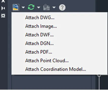
STEP-2
After affixing Left click on the attached drawing file .Bind the attached file and then explode the drawing file.
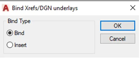
Click on the layout tab right click it and make a new layout. Rename the layout tab as plan and section. Remove the present view port shown in the layout.
STEP-3 To make the template
Use command "LAYOUT" choose template (dwt) - choose "m Arch." from the dialogue box, choose ISO A1 layout and re name it as Layout of Plan and Section. Type “MS" for the activation of model space.
STEP-4 To make viewport
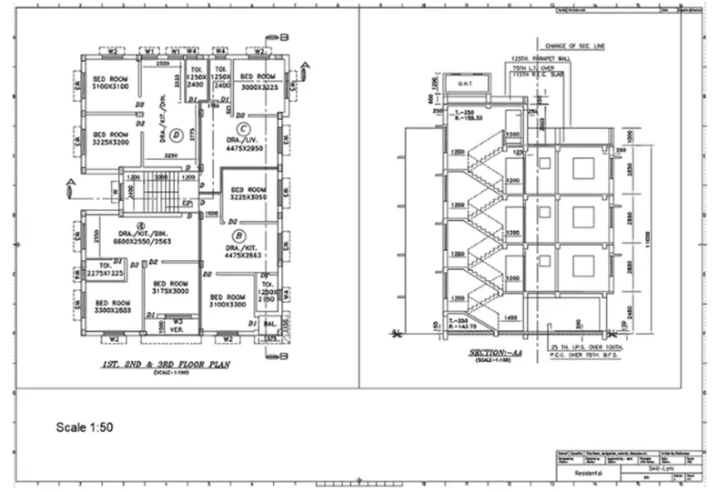
Draw a rectangle of size 400x455 and 375x445 for making the viewport.
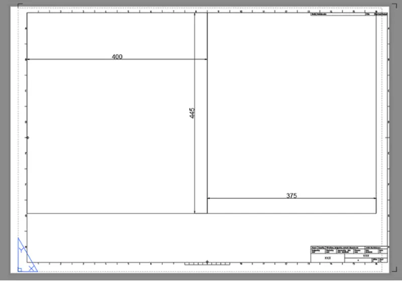
Use the command "MV" multiple view- choose object option and click on the rectangle, and then the drawing will be shown in the viewport. Accordingly, do it for the second rectangle.
Command "MS" for model space and click on the viewport we need to set the drawing. Click on the first viewport and zoom in the drawing for the plan and give a scale of 1:50 and lock the viewport so that further zooming will not change the scale.
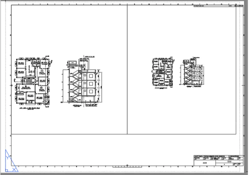
Accordingly does it in second viewport zoom in the section view, making it a scale of1:50 and lock.
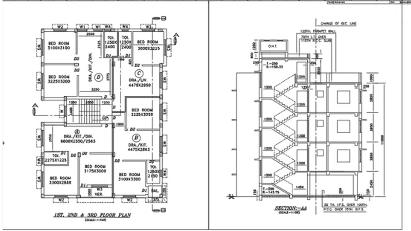
STEP-5 Editing Attributes in the template
Go to paper space by command “PS" and click on the template which is a block. Click on the attributes and edit the attributes- double click the attribute text or command "ATTEDIT”, the attribute dialogue box appears. Provide the value as NAME, DATE, scale etc.
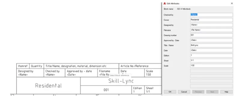
Enter the text by multiline text in paper space and with text height 20.
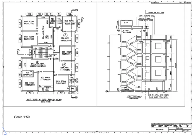
STEP-6 Taking plot utilizing A1 sheet
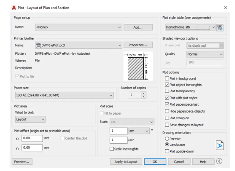
Use command "PLOT”, the dialogue box appears. Provide the name as "DWG to PDF". Choose the paper size as ISO A1 (594x841 mm). Choose what to plot as layout. Scale is provided as 1:1, orientation is provided as landscape. Choose the pen assignment as "Monochrome" so that the print will be in lack.
RESULT:
Layout is created utilizing template m. Arch. dwt. Viewport is generated utilizing MV command of size 400x445 and 375x445mm and the scale of viewport is set to 1:50. Attributes in the template are edited. A plot is taken utilizing A1 size.
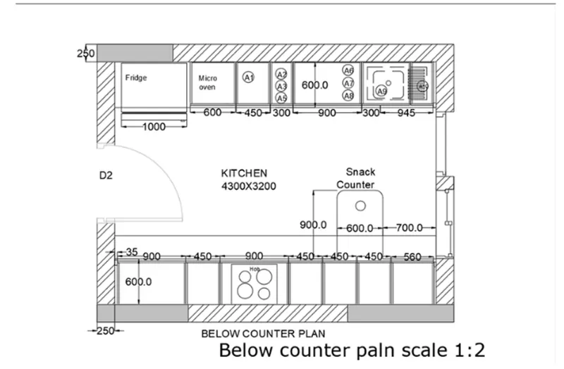
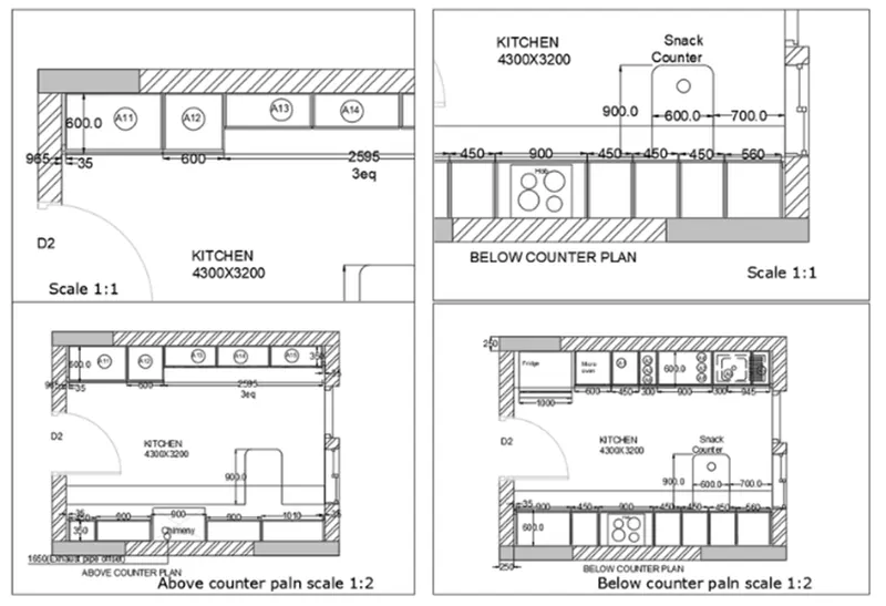
Q.2 Make a layout of the Kitchen drawn in Challenge 9 as given in Picture. Utilize the scale as given in the Picture. Use A4 Size page for the layout. Take a plot.
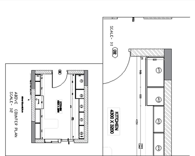
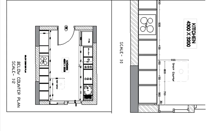
AIM: To take different view of kitchen for layout in model space, make the layout with four viewports, with A4 sheet, make a plot.
INTRODUCTION: The layout is created in Auto CAD by utilizing the scale provided in the picture. The methods explained in detail with pictures of each step and the final result is provided.
PROCEDURE:
STEP-1
In the command prompt enter "XREF" and on the left corner affixthe Dwg. Affix the drawing.
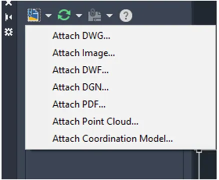
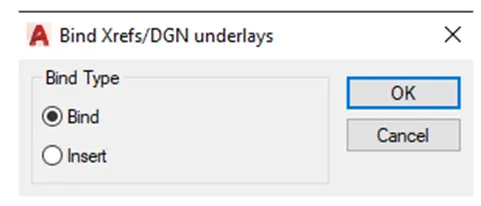
After affixing Left click on the attached drawing file .Bind the attached file and then explode the drawing file.
STEP-2
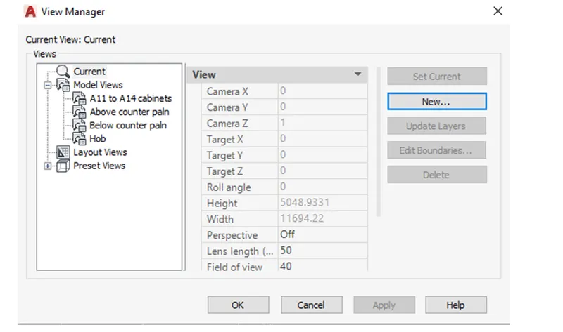
Take different views for the layout in model space. Open the drawing, use command "VIEW" to make new views. The view manager dialogue box appears. Click on model; click on new to make new view.
Another dialogue box of new view appears, give the view name as "above counter plan" choose the boundary as define window, and choose it utilizing the window choose icon from the drawing.
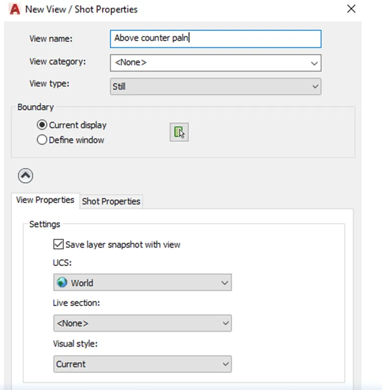
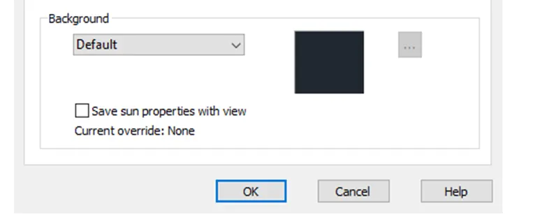
Click on OK and the view with name above counter plan and the choose drawing will be created. Accordingly make views for below counter plan, hob, and A11 to A14 cabinets.
STEP-3
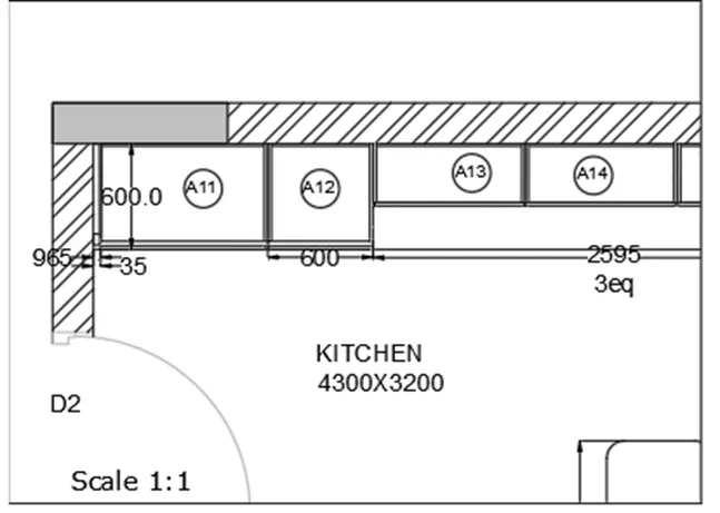
Make the layout with four viewports, with A4 sheet. Open the layout tab; rename the layout as kitchen layout. Remove the present viewport. Default is the A4 sheet. "MV" commands make4 viewports by making the window. Type command "VIEW" in the layout tab, choose the needed view and click on the viewport where it has to be displayed and lock each viewport. Choose the A11 to A14 cabinet view in the first viewport, zoom and pan to fit in the viewport. Go to paper space, with Text command type SCALE 1:1.
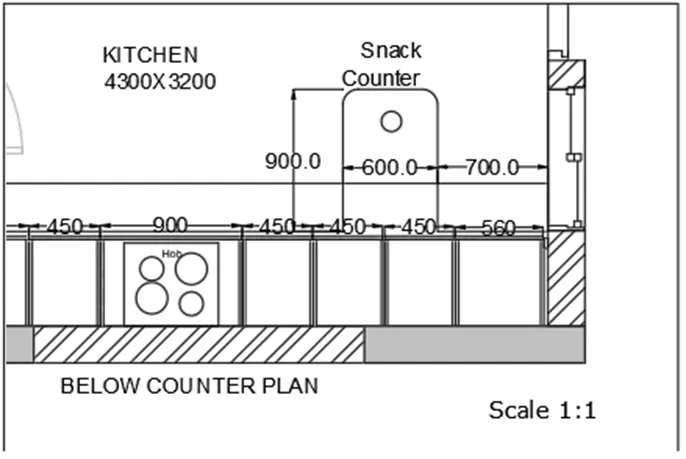
Enter command "MS" click on the second viewport. Enter the command "VIEW" and choose the view name snack counter. Zoom and pan the viewport to make the view fit in the viewport. Lock the viewport. Go to paper space and with command "T" enters the text SCALE 1:1.
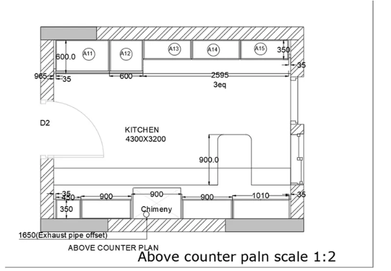
Accordingly, in model space click on third viewport. Enter the view above counter plan. Zoom and pan the viewport, so that the drawing fit in it. Lock the viewport. Go to paper space and with command "T" enters the text as ABOVE COUNTER PLAN and SCALE 1:2 with text height 3.5.
Accordingly, in model space click on third viewport. Enter the view below counter plan. Zoom and pan the viewport, so that the drawing fit in it. Lock the viewport. Go to paper space and with command "T" enters the text as BELOW COUNTER PLAN and SCALE 1:2 with text height 3.5.
STEP-4
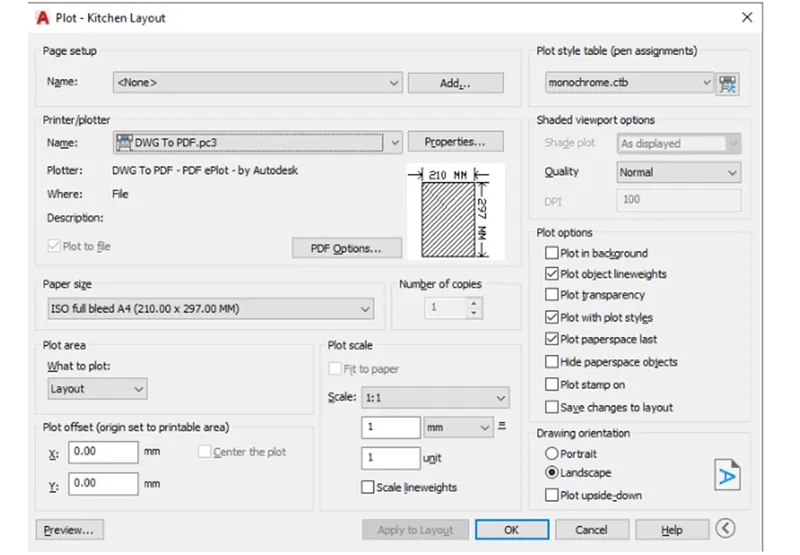
Making a plot Use "PLOT" command, plot dialogue box appears. Paper size is choose as A4 and name is provided as A4, printer name ad print to pdf. Choose what to plot as layout, and choose pen assignment as monochrome. Preview the print. Choose ok to convert to pdf.
RESULT:
Different view of kitchen for layout in model space is created, layout with four viewports, with A4 sheet is made, a plot is generated.
Q 3. Make a layout of the section generated in Challenges 9. Utilize scale as mentioned in the Picture. Use MV command make multiple viewports. Take a plot.
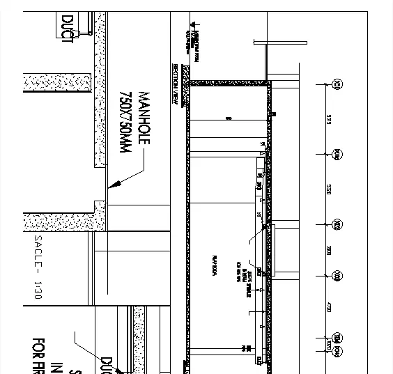
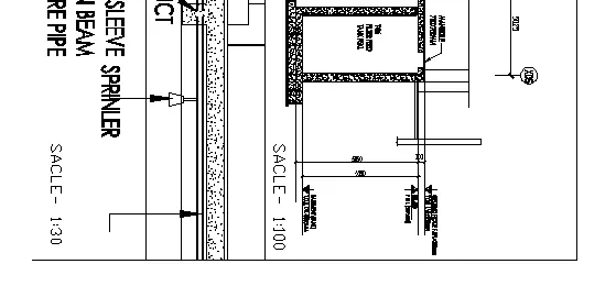
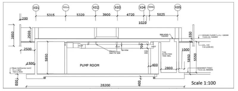
AIM: Make layout of the section of industrial building, making viewport by MV command (Multi view port) and scale 1:30 and 1:100 is provided, to take a plot of the layout.
INTRODUCTION: The layout is created in Auto CAD by utilizing the scale provided in the picture. The method is explained in detail with diagrams of each step and the final result is provided.
PROCEDURE:
STEP-1
In the command prompt enter "XREF" and on the left corner affix the Dwg. Affix the drawing.
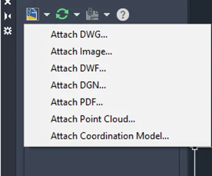
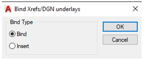
After affixing Left click on the attached drawing file .Bind the attached file and then explode the drawing file.
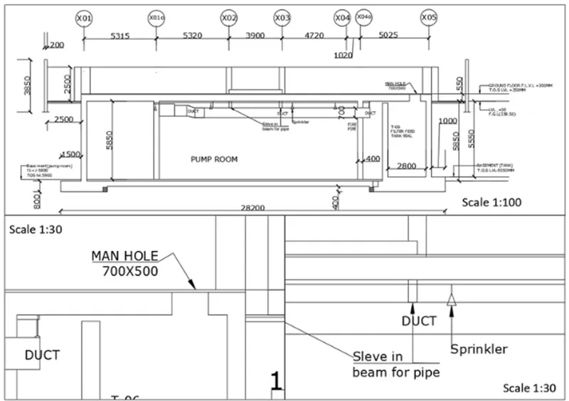
Making layout of the section of industrial building. Open the drawing of section of industrial building. Take the layout tab .Re name the tab as industrial section. Right click on the tab and choose page set up manager option. Click on new - give a name, page setup dialogue box show up.
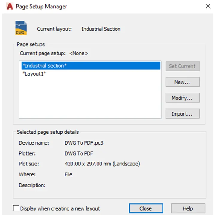
Click on Modify. Provide the paper size as A3 in page setup dialogue box. Make it current, the layout paper size changes to A3. Use "MV" command and make3 viewports accordingly.
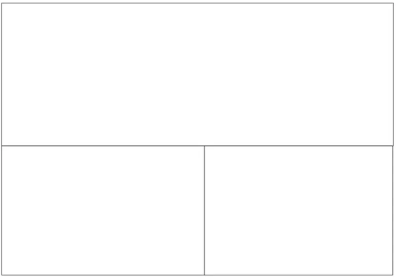
Use Command "MS" for the model space, click on the first viewport .Set the scale to 1:100 from the bottom toolbar or right click and properties, from there also we can change the scale. By pan command fit the drawing inside the view port. By text command writes the text as SCALE1:100 with a text height of 6 and lock the viewport.
STEP-2
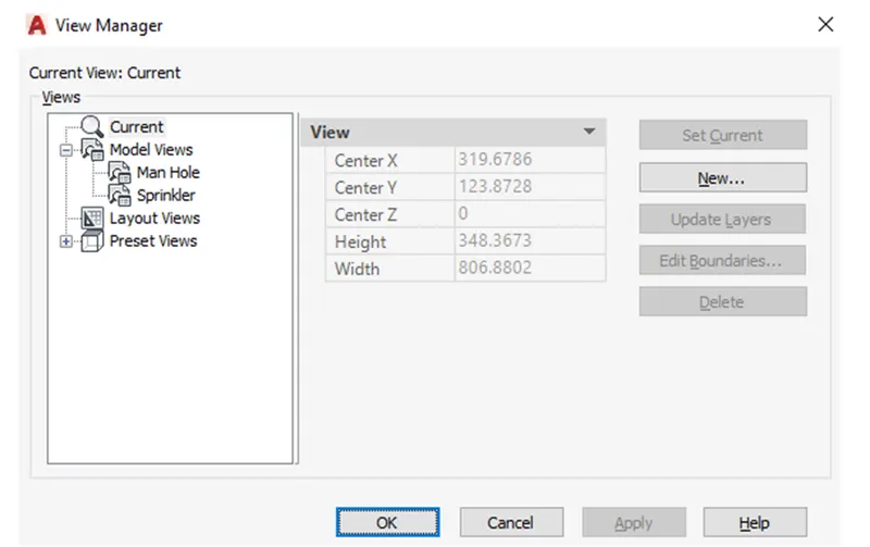
Go to model view, and make views for the next two viewports. Command "VIEW" -view manager dialogue box appears –make new-give name as manhole view -choose define window and choose the view we need to create, press enter. Accordingly make view for sprinkler named as sprinkler view.
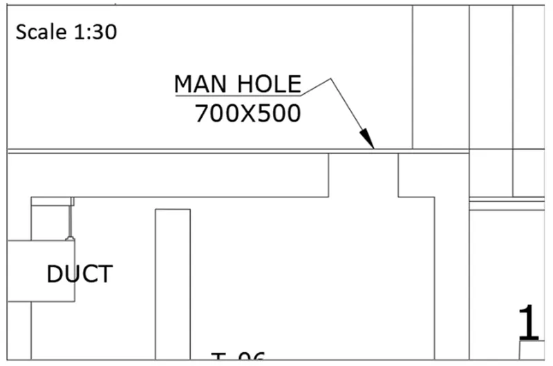
Now go to the layout industrial section and command "MS" and click on the left model space. Now use command "view" -choose the manhole view- and click on set current. Then the view will be displayed on the model space Choose the scale to 1:30 from the bottom toolbar. By multiline text give the text as SCALE 1:30 with a text height of 6.Lock the viewport from the bottom toolbar lock symbol.
STEP-3
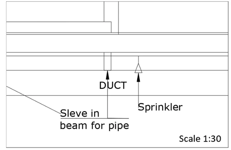
Type "MS" and click on the third viewport. Use command "VIEW" and choose the sprinkler view and make it current. Choose the scale to 1:30 from the bottom toolbar .By multiline text insert the text as SCALE1: 30 with a text height of 6.Lock the viewport.
STEP-4
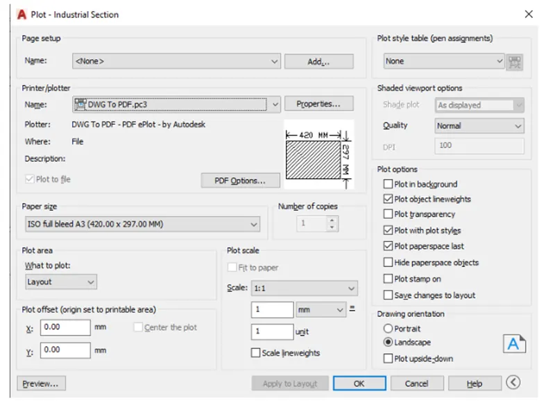
Take a plot of the viewport. Enter the command "PLOT". The dialogue box appears choose paper size as A3, what to plot as layout .Provide pen assignments as monochrome.
RESULT:
- Layout of the section of industrial building is generated, view port is generated by MV command and scale 1:30 and 1:100 is provided.
- Plot of the layout is taken.
RESULT:
- Layout of plan and section, viewports, editing attributes is created and a plot is taken.
- Kitchen layout in A4 sheet is generated and plot is taken.
- A Multi view port for industrial section drawing is generated, scaling and plotting is done.