Creation of Multiple viewports, Scaling the drawing and setting in Template in AutoCad
|
Creation of Multiple viewports, Scaling the drawing and setting in Template in AutoCad |
PROBLEM 1
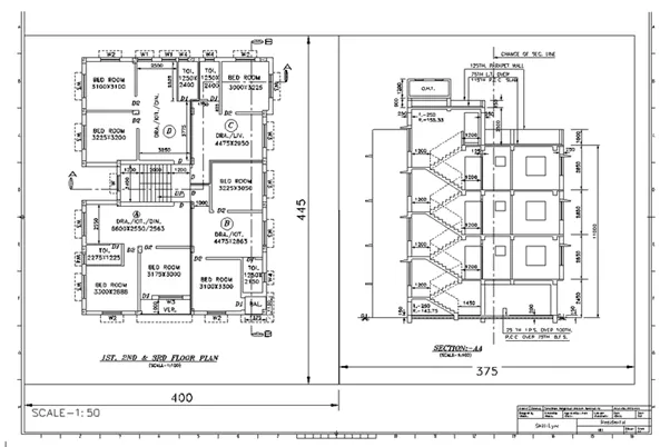
- Aim :- Create a layout of the Plan and Section A of the project in Challenges 7, using the template Tutorial mArch.dwt in a scale as given in the Figure.
- Introduction :-
The general commands used for drawing the building is as follows :
- Line
- Polygon
- Rectangle
- Circle
- Erase
- Copy
- Trim
- Mirror
- Offset
- Extend
- Array
- Move
- Rotate
- Dimension
- Text
- Fillet
Etc.
The dimensions:
- For external wall – 250mm
- For internal wall – 125mm
- For Staircase : - Treads : 250mm, Rise : 150mm
The assumed dimensions :
For Windows:
- W – 1000 X 1500
- W1 – 900 X 1200
- W2 – 1200 X 1200
- W3 – 1500 X 1200
- W4 – 700 X 500
For Doors:
- D – 1000 X 2000
- D1 – 750 X 2000
- D2 – 900 X 2000
- Procedure :-
- Click on AutoCAD application and open this application
- Open the drawing which is already drawn in challenge 9
- Take view command
- Click > New
- Specify view name > Plan
- Select > Define window
- Select the window for plan
- Enter
- Take view command
- Click > New
- Specify view name > SectionAA
- Select > Define window
- Select the window for Section AA
- Enter
- To create layout
- Right click on Layout1
- Select > From Template
- Click > Tutorial-mArch
- Ok
- Right click on new layout > Rename
- Rename > Plan-Elevation
- Open the Plan-Section layout
- Take rectangle command
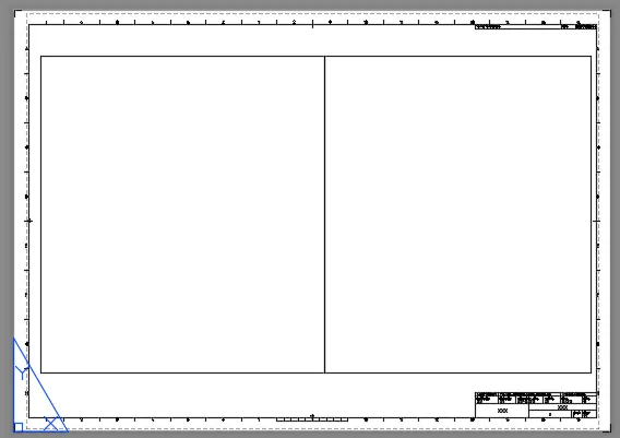
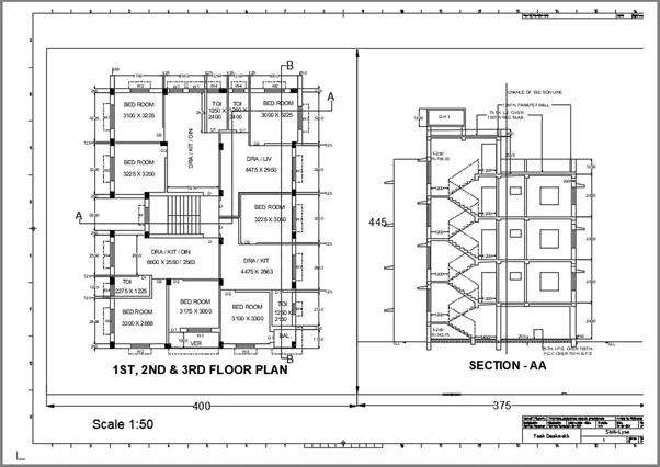
- Create the two rectangle as shown below
- One rectangle having dimension > 400, 445
- Other rectangle having dimension > 375, 445
- Take Ms command
- Take MV command
- Select > Object
- Click the one rectangle
- Enter
- Similarly do for the another rectangle
- The two view ports are ready
- Type v in command bar
- One dialogue box will open
- Click > Plan > Set current > Ok
- Again do similar process for Section AA for other view port
- Select Scale > 1:50
- Select the two view ports
- Go to properties
- Make it lock
- Take Ps command
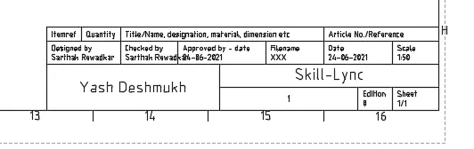
- Type > ATTEdit
- Enter
- Select the object as template
- Edit the attribute as per requirement
- The attribute is ready as shown below
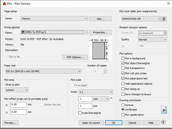
- Type plot in command bar
- Dialogue box will open
- The setting is done as per below
- The layout is ready
- Result :-
PROBLEM 2
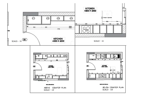
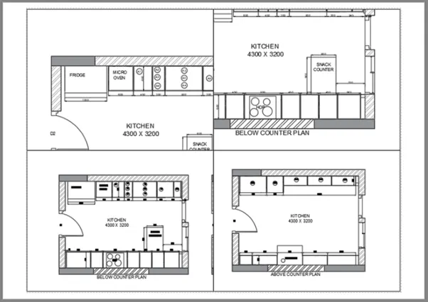
- Aim :- To create the layout of the kitchen as shown below by using the view ports.
- Procedure :-
- Click on AutoCAD application and open this application
- Open the drawing which is already drawn in challenge 9
- Take page setup command
- Click > New
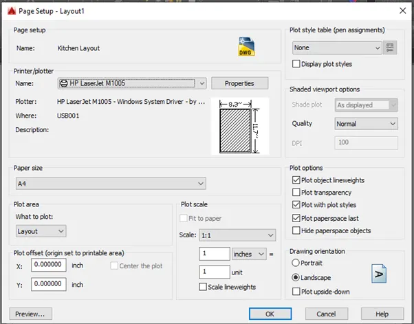
- Page setup Name > Kitchen layout
- Set the settings as per shown below
- Enter
- Click > Set current
- Enter
- Take view command
- Click > New
- Specify view name > Kitchen-Above Counter plan
- Select > Define window
- Select the window for plan
- Enter
- Similarly do the same procedure to create other views
- To create layout
- Right click on Layout1
- Right click on new layout > Rename
- Rename > Kitchen
- Open the Kitchen layout
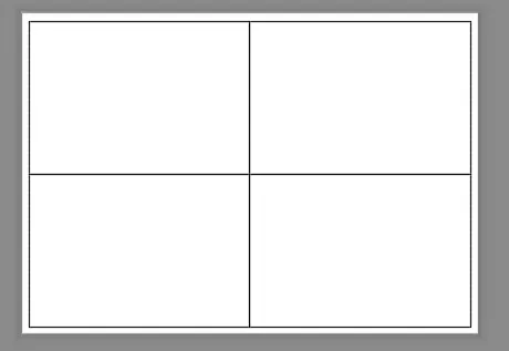
- Type > MV > enter
- Specify > 4
- Select the corner as it will gives following results
- Take Ms command
- Take MV command
- Select > Object
- Click the one rectangle
- Enter
- Similarly do for the another rectangle
- The two view ports are ready
- Type v in command bar
- One dialogue box will open
- Click > Kitchen-Above counter Plan > Set current > Ok
- Again do similar process for other view port
- Select Scale > as per view ports shown in drawing
- Select the all view ports
- Go to properties
- Make it lock
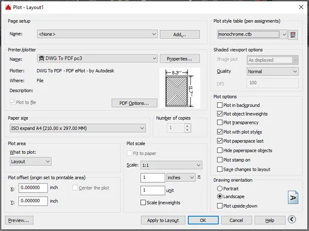
- Type plot in command bar
- Dialogue box will open
- The setting is done as per below
- The layout is ready
- Result :-
PROBLEM 3
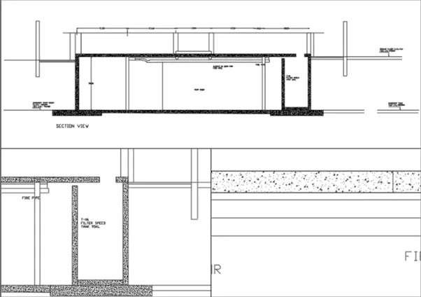
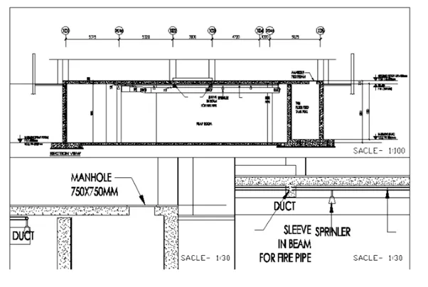
- Aim :- To create the layout of the Industrial Building as shown below by using the view ports.
- Procedure :-
- Click on AutoCAD application and open this application
- Open the drawing which is already drawn in challenge 9
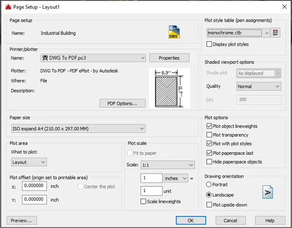
- Take page setup command
- Click > New
- Page setup Name > Industrial building layout
- Set the settings as per shown below
- Enter
- Click > Set current
- Enter
- Take view command
- Click > New
- Specify view name > Section View
- Select > Define window
- Select the window for view
- Enter
- Similarly do the same procedure to create other views
- To create layout
- Right click on Layout1
- Right click on new layout > Rename
- Rename > Industrial Building
- Open the Industrial Building layout
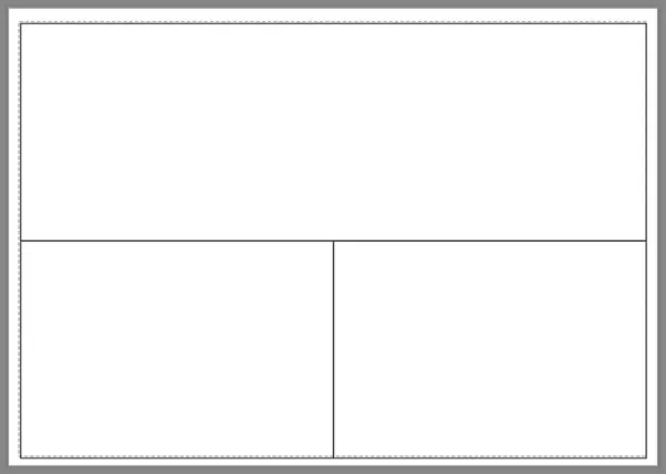
- Type > MV > enter
- Specify > 3
- Select the corner as it will gives following results
- Take Ms command
- Take MV command
- Select > Object
- Click the one rectangle
- Enter
- Similarly do for the another rectangle
- The two view ports are ready
- Type v in command bar
- One dialogue box will open
- Click > Kitchen-Above counter Plan > Set current > Ok
- Again do similar process for other view port
- Select Scale > as per view ports shown in drawing
- Select the all view ports
- Go to properties
- Make it lock
- Type plot in command bar
- Dialogue box will open
- The setting is done as per below
- The layout is ready
- Result :-