Creation of Multiple viewports, Scaling the drawing and setting in Template in AutoCad
AIM
To create a layout of the plan and section-A of the project in challenge 7 using the template And use the MV command to create the viewport of the size from the given figure.
INTRODUCTION
- Plans and Sections are different types of drawings used by architects, to graphically represent a building design
- A plan drawing is a drawing on a horizontal plane showing a view from above.
- An Elevation drawing is drawn on a vertical plane showing a vertical depiction.
- A section drawing is also a vertical depiction but one that cuts through space showing what lies within.
COMMANDS USED
- Limits command
- Line command
- Offset command
- Hatch command
- Dimlinear command
- Dimstyle command
- Units command
- Extend command
- Fillet command
- Trim command
- Join command
- Line weight command
- Line type command
- Object snap command
PROCEDURE
STEP-1
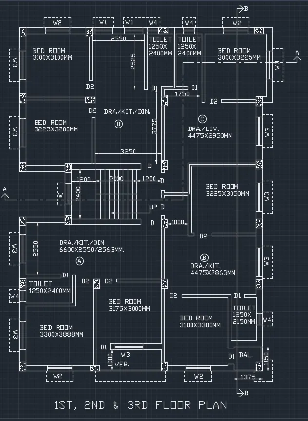
1st, 2nd and 3rd Floor plans
- First open the AutoCAD and set the limits using the limits command
- Next, draw the line with the length of 16388mm from down to up horizontally
- Next draw the line from the previous line with the length of 12150mm horizontally forwards. Next draw the line from the previous line with the length of 16388mm downwards vertically.
- Next draw the line from the last line to the first line to form the rectangle
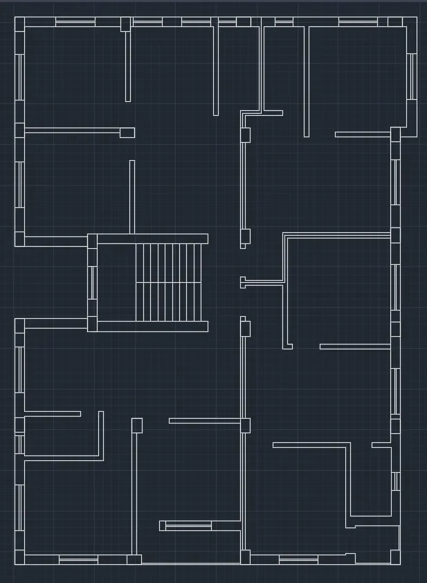
- draw the rooms with help of line command and offset command and trim command, with the lengths given in figures
- Draw the bedroom with the length of 3100mm and width of 3100mm Next, draw the another bed room with the size of 3225mm x 3200mm
- draw the drawing/kit/din room with the size of 2550mm x 3775mm x 3250mm
- Next draw two toilets with the sizes of 1250mm x 2400mm
- Next draw another bed room in the part C with the size of 3000mm x 3225mm
- draw the draw/liv with the size of 4475mm x 2958mm
- draw the bed room in the part B with the size of 3225mm x 3050mm
- Next draw the draw/kit room with the size of 4475mm x 2863mm
- draw the toilet room with the size of 1250mm x 2150mm the size of 3100 x 3300mm
- Next draw another bed room with the balcony with size of 1375mm x 1100mm
- draw the bed room in the A part with the size of 3175mm x 3000mm
- leave some space for the veranda, with the length of 3175mm. Next, draw another bedroom with the size of 3300mm x 2888mm.
- Next trim the unnecessary lines and objects. Then draw the columns with the size of 250mm x 350mm.
- The columns are placed where ever they required in the floor plan.
- Next draw the windows and doors with the sizes are shown below.
- W1 - 900 x 1200mm
- W - 600 x 1200mm
- W2 -1000 x 1200mm
- W3 - 1500 x 1200mm
- W4 - 500 x 500mm
- D - 1000 x 2100mm
- D1 - 1000 x 2100mm
- D2 - 900mm x 2100mm
- Finally, indicate the rooms using the single text command.
- And provide the dimensions for the given floor plan using the dimlinear command.
- And also draw the section lines as given in the figure, and also indicate the doors and windows.
STEP-2
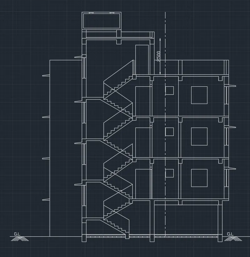
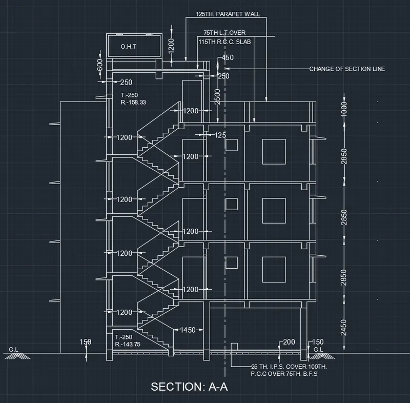
Section-AA
- First draw the line with the length of 8900mm horizontally forward
- draw another line from the previous line vertically with the length of 1mm.
- draw the line from the previous line with the length of 11000mm horizontally backwards from the previously drawn line
- Next draw the line from the first line and the last line we drawn previously, Next do the offset to the particular lines with the given offset values ground
- The inner wall offsets are 125mm and outer wall thickness is 250mm. And level thickness is 200mm and 150mm.
- Next draw the windows in their requires places in 1st, 2nd and 3rd floors
- Here next draw and take the line type as dashed lines and set it to the particular value of the dashed lines for the staircase the stairs with tread of 250mm and the riser with 143.75mm and 158.33mm
- Next draw the remaining parts, we draw the parapet wall and water tank (O.H.T) at the top of the building
- Next draw the doors at their required places in the first second and third floors
- Next remaining we draw the windows and sunshades in their particular places.
- Next, select layers and make them to the different colours for different parts in the section, as shown be Next we put the dimensions where ever they are required in the section drawing as shown below.
- Next select the single text command to indicate the parts in the section plan
- Finally draw the section line in the section plan as in the below figure.
STEP-3
- First select the layout at left side corner of the screen.
- After selecting the layout rename the layout as floor plan.
- Next give MV command and select the template.
- After selecting the template, select the Tutorial-mArch as shown in the figure.
- After selecting the template, rename the template text using the attedit command.
- First insert the floor plan in the paper using the MV command.
- After clicking the MV command to drag the paper with rectangle shape with standard size
- After dragging rectangle on the template paper, the current floor plan will be appear, then we put them in to the scale of 1:50.
- Next edit the template box, using the attedit command
- First select paper spacing command, then after we use the attedit command to edit the template box, as shown in the below figure
- After editing the template box, use the plot command to covert the drawing in to the .pdf file, as shown in the figure
- Finally convert the DWG to pdf file using the plot command as shown in the above figure
- Next select the Al paper size for fit the drawing in the paper as shown in the below figure.
RESULT
Created a layout of the plan and section-A of the project in challenge 7 using the template. And created the viewport of the size using the MV command. Created a layout of the plan and section-A of the project in the autocad in detail.
AIM
To create the layout of the kitchen and providing hatches to it using the autocad in detail Need to use the scale given in the figure and need to use the A4 size page for the layout.
INTRODUCTION
- kitchen layout is the most important part of designing your perfect kitchen.
- It's the layout that will determine how you cook, how you eat and how you socialise So whether you're totally remodelling the kitchen,
- buying new appliances or simply replacing the cabinets, we've included the top five most common kitchen layouts to help inspire you.
COMMANDS USED
- Limits command
- Line command
- Offset command
- Hatch command
- Dimlinear command
- Dimstyle command
- Units command
- Extend command
- Fillet command
- Trim command
- Join command
- Line weight command
- Line type command
- Object snap command
PROCEDURE
STEP-1
Below counter plan
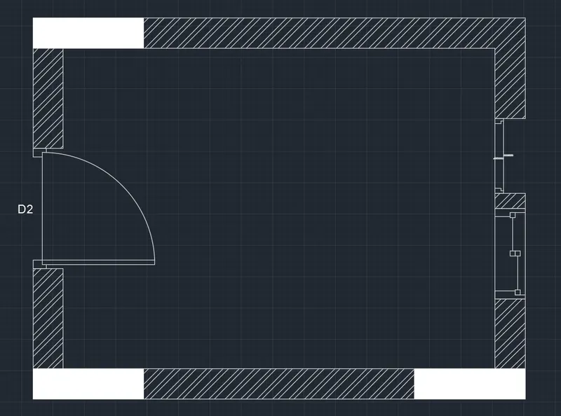
- First have to draw the line horizontally with the length of 4300mm
- Next draw another line from the previous line with the length of 3200mm vertically upwards.
- Next again draw the line from previous line with the length of 4300 mm horizontally backwards at the top.
- Next join the first line and the last line which we have drawn previously. Next offset the four sides with the offset of 20mm outside.
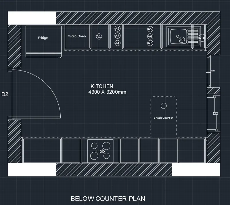
- Next offset the line inside with the offset command with the length of 600mm, including the fridge.
- Afterwards draw the fridge separately with other dimensions in the kitchen layout.
- Next need to draw the line opposite side to create the parts of kitchen.
- Next divide the seven parts downsides with different dimensions compared to the upper side portion Next leave the space left and right corners with the length of 35mm at the top and Bottom
- Next put the dimensions for every part in the diagram. Next indicate the door as D2.
- Next have use the single text command and indicate the parts where ever it requires with single text command.
- And put the dimensions for every part in the diagram.
- Next draw the snack counter with the length of 600mm and width of 900mm, and draw the circles to create the hub in the middle at the bottom of the kitchen
- And create the windows using the line command and trim command, which is shown in the below figure
STEP-2
Above counter plan
- First have to draw the line horizontally with the length of 4300mm.
- Next draw another line from the previous line with the length of 3200mm vertically upwards
- Next again we draw the line from previous line with the length of 4300 mm horizontally backwards at the top.
- Next have to join the first line and the last line which we have drawn previously.
- Next offset the four sides with the offset of 20mm outside
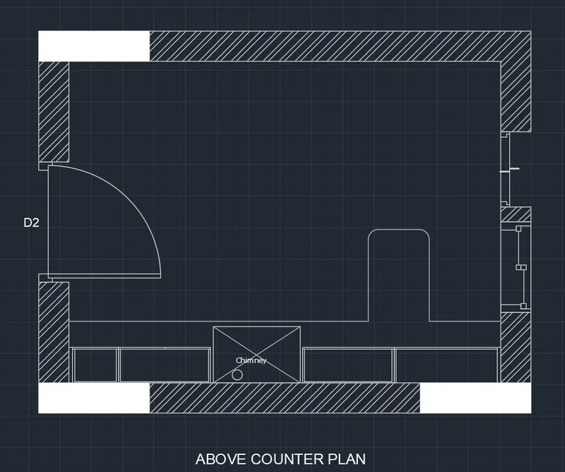
- Next have to offset the line inside with the offset command with the length of 350mm, and again do offset of 600mm in the same side.
- And leave the space for both side comers with the length of 35mm and do offset for the inside parts with the length of 10mm for all sides of the all parts in the kitchen layout.
- Next do the offset of 350mm at the bottom portion of the kitchen. And the bottom portion into five parts, and again offset them with the length of 10mm.
- Next use the different hatch styles to hatch the walls in the kitchen layout. Next, we have to draw the doors using the line command, circle command and trim command.
- Next have to draw the windows using the line command and trim command and next we have to use the Dimlinear command to put the dimensions where ever they are required.
- Next use the single text command to indicate the kitchen parts in the kitchen layout which we have drawn in the below figure.
- Finally draw the snack counter with the length of 600mm and width of 900mm.
STEP-3
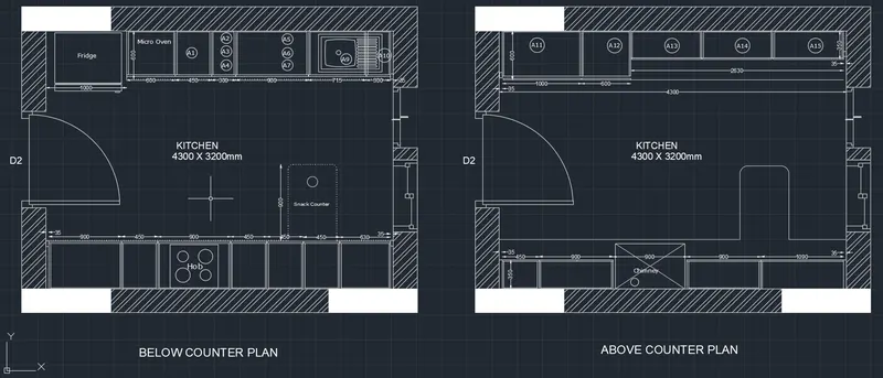
- First select the layout at left side corner of the screen. After selecting the layout rename the layout as floor plan.
- Next create the 1st view using the MV command, that we take the scale as 1:1
- Next create the 2nd view using the MV command, that we take the scale as 1.1
- Next create the 3rd view using the MV command, that we take the scale as 1:2
- Next create the fourth view using the MV command, that we take the scale as 1:2
- Finally convert the DWG to pdf file using the plot command as shown in the above figure
- select the Al paper size for fit the drawing in the paper as shown in the below figure.
- Next select the pen assignments as monochrome.ctb.. Then select the apply to layout and click the ok option.
- Then finally the dwg file is exported to the pdf file as shown in the below figure.
RESULT
Created the layout of the kitchen and provided hatches to it using the autocad in detail Used the scales given in the figure and provided A4 size page for the layout.
AIM
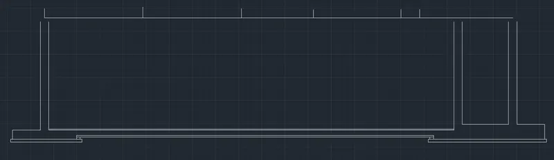
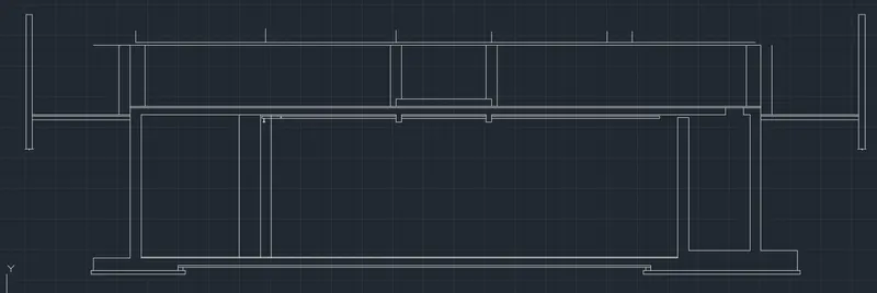
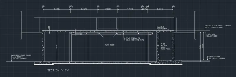
To create the section view of an industrial building. And need to provide appropriate hatches and dimensions where ever required.
INTRODUCTION
- In reference to architectural drawing, the term section typically describes a cut through the body of a building, perpendicular to the horizon line
- A section drawing is one that shows a vertical cut transecting, typically along a primary axis, an object or building
- A section diagram is a view of the building that slices through the building to better see the specific aspects of the building better
- This drawing is particularly interesting because it cuts through and goes underground (to the new parking area) as well.
COMMANDS USED
- Limits command
- X-Line command
- Line command
- Offset command
- Hatch command
- Dimlinear command
- Dimstyle command
- Units command
- Extend command
- Fillet command
- Trim command
- Join command
- Line weight command
- Line type command
- Object snap command
- Rectangle command
- Zoom command
PROCEDURE
STEP-1
- First draw the X-line at any point on the screen.
- Next offset the line to top to a distance of 5850mm and we have to do offset of last offset line to the distance of 300mm to the top
- Next draw the vertical X-line on any point on the horizontal line.
- Next do offset of line to right to a distance of 10635mm Next offset the last line with a distance of 3900mm to the right
- Next offset the 1st line with the distance of 5740mm to the right side.
- Next offset for last line with the distance of 5025 to the right side.
- Offset the left and right edges with the distance of 500mm.
- Next trim the outer edges using the trim command.
- Next offset the bottom edge of the top floor to a distance of 30mm.
- Next offset the last line with a distance of 70mm to the bottom.
- Next offset the last line with the distance of 100mm to the bottom.
- Next draw the sprinkler pipe along with the duct pipe.
- The duct pipe thickness is 300mm and the thickness of sprinkler pipe is 100mm.
- Next draw the manhole cover with the thickness of 750mm at the right top edge of filter feed walls as shown in the figure
- Next draw the thickness of pump room slab with the different layers using the line command.
STEP-2
- Next draw the circle with radius of 500mm, and enter the text in the circle as given in the figure.
- Next use the single text command to enter the text where ever required in the section view of industrial drawing
- Finally use the hatch command to hatch the walls and floor slabs as drawn in the below figure.
- Finally use the Dimlinear command to put the dimensions wherever required in the drawing.
STEP-3
- Next select the MV command to create the new view
- Then after when we see on the screen the view manager tab will display then select the view option
- After selecting the new option in the view manager as shown in the figure, and select the boundary on that tab as current display
- Next create the 1st view using the MV command, that we take the scale as 1:100
- Again, select the MV command and select the new option and create the 2nd view as shown in the figure
- Next create the 2nd view using the MV command, that take the scale as 1:30
- Now create the 3rd view using the MV command, that we take the scale as 1:30
- Finally convert the DWG to pdf file using the plot command as shown in the above figure.
- Next select the Al paper size for fit the drawing in the paper as shown in the below figure
- Next select the pen assignments as monochrome.ctb.. Then select the apply to layout and click the ok option.
- Then finally the dwg file is exported to the pdf file as shown in the below figure.
RESULT
Created the section view of an industrial building. Used the scales given in the figure and created the multiple viewports using the MV command, in the autocad in detail.