Creation of Multiple viewports, Scaling the drawing and setting in Template in AutoCad
1) Aim & Introduction
Aim:
This challenge aims to provide an experience to the student in sketching a full plan and elevation of a building. This will allow the student to utilize all the AutoCAD tools in multiple uses. The AUtoCAD software provides different tools that when utilized together can from any sketch that followa in the imagination. A building part of the civil engineering industry and this correlates the AutoCAD software with the civil engineering industry. This challenge aims to give the student deeper understanding on how to utilize the AutoCAD software in sketching a residential building house
Introduction:
The AutoCAD software provides different tools. used in this challenge is as described below:
Line- creates line object
Polyline- creates rectangle line object Rectangle- creates rectangles object Circle- create circle object
Trim-Cut unwanted lines or shapes with the provided cutting edges
Extended- Extend lines to opposite corners
Move- Move objects to particular locations
Copy- Copy obejects to particular locations
Rotate- Rotate selected objects to a particular angle with respect to base point
Array- Copy an object in a set path linearly or polarly
Join- Joins separated line objects to a particular angle with respect to base point
Dimlinear(DLI)- provides vertical or horizontal linear/ straight dimensions
Dimligned(DAL)- Provides dimensions with respect to the angle of the object
Dimangular(DAN)- Provides angular dimensions between two line objects.
Quicklinedimension(QDIM)-provides quick dimension of a geometry
Leader- creates an arrow head line
Layer- Provides identification of line or object groups by their properties
Units- Open "Drawings Units" window to specify to modify the dimension properties
Hatch- provides hatching pattern in a given object or internal point
Sketch and Procedure:
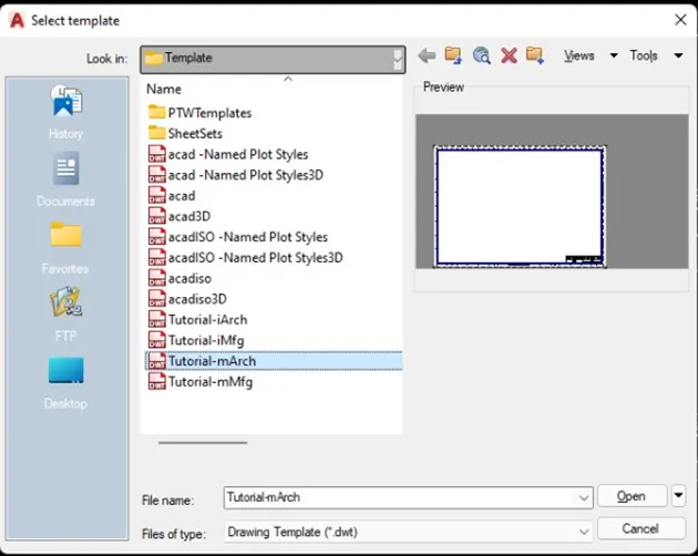
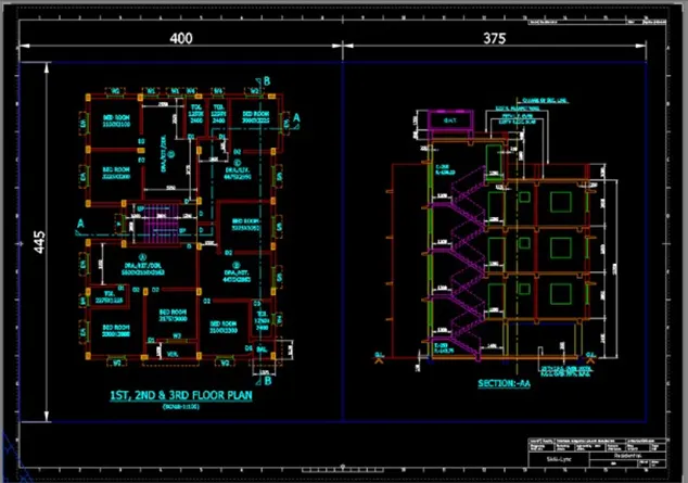
Create a layout of the plan and section A of the project in challenge 7, using the template Tutorial-mArch.dwt in a scale as given in the figure. Use the MV command to create the viewport of the size as shown in figure. Also, use ATTEDIT command to edit the information in the title Use A1 size for the layout. Take a plot
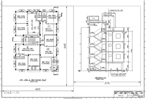
PROCEDURE:
Open a CAD and select the Tutorial-mArch as template
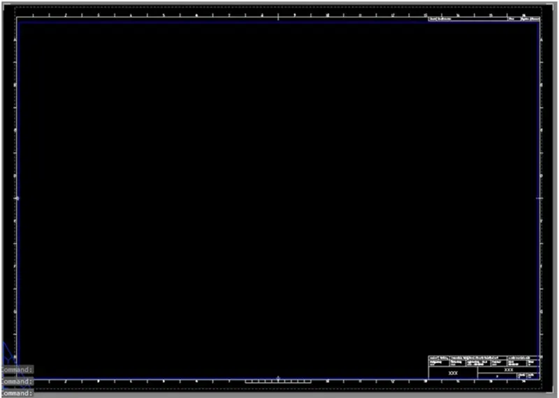
Replace the text as required

----->Proceed to the drawing. Sketch the floor plan
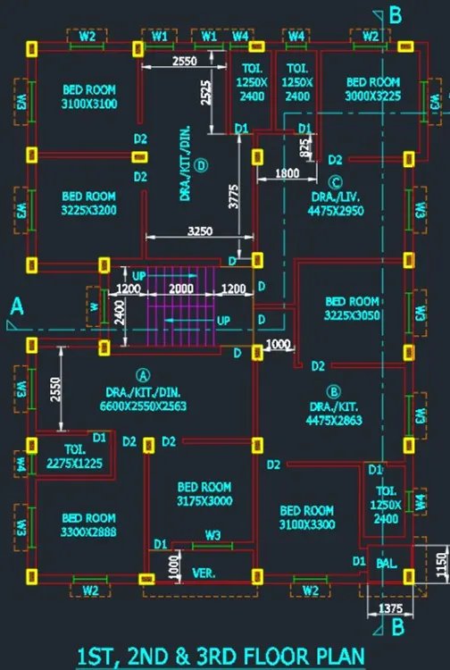
Create the boundaries using XLINE command

Cut the lines using trim tool and offset by 250 for the walls
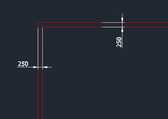
Sketch the bedroom. Use offset command and trim to make the lines
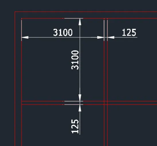
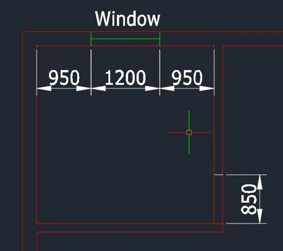
Create the opening boundary and window designation
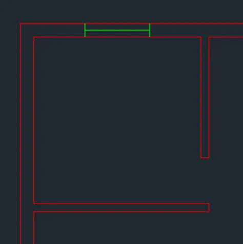
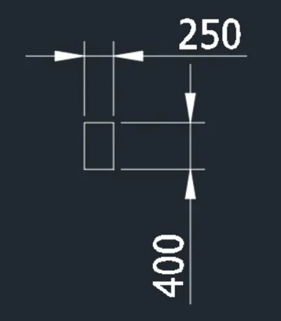
Add the column designation. Column dimension is 250x400
To skatch the column. Use rectangle tool and hatch the object using the AR-CONC pattern
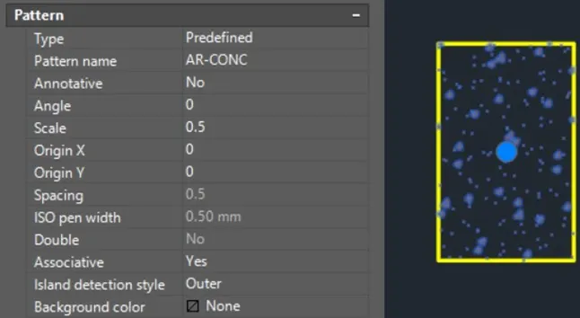
Apply the CTRL+C and CTRL+V function to create object as block
Use move and copy tool to move the column object around the sketch. Copy the column object where it is required. Use rotate tool in cases the column is in horizontal form
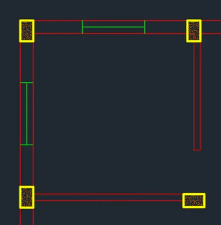
Proceed with the sketch of DRA/KIT/DIN Mind the last bedroom space as it will be adjusted later for stair space
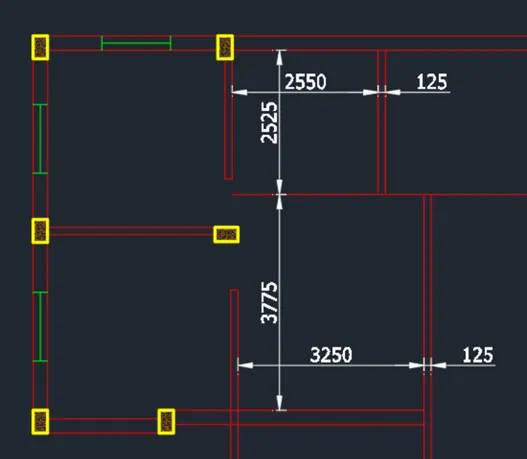
Use trim tool to delete the unnecessary lines
CReate the windows. Length is 850
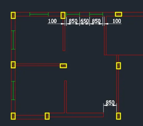
Proceed with the sketch of the toilet. Use the same procedures and tools to sketch
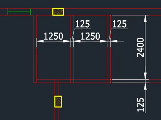
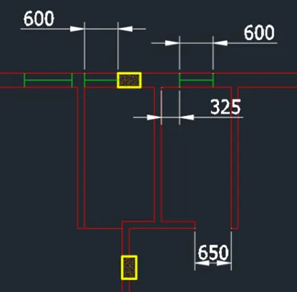
After sketching the 2 toilets proceed with the bedroom
Stretch the created wall for easier procedure
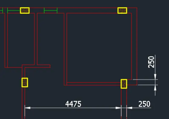
Add the doors and window
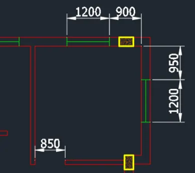
Sketch the DRA/LIV and bedroom below mind the hailway leading to the stairs
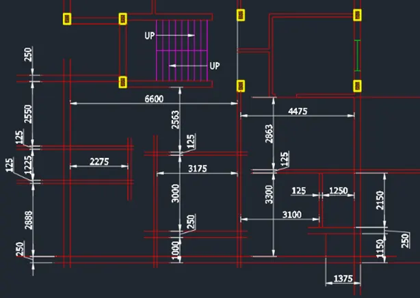
Use fillet tool and trim tool to create the edges
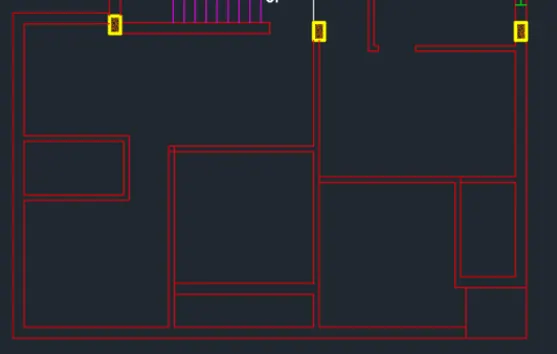
Continue with the toilet and bedroom sketch teh columns and windows provide door openings
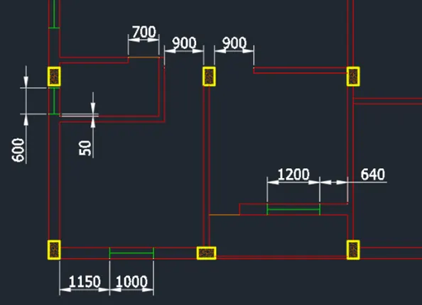
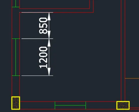
Once finished proceed the other side
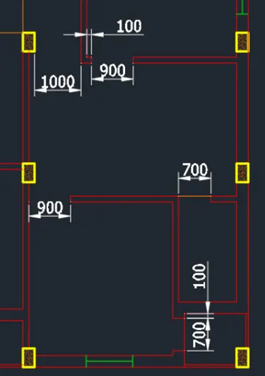
Do this to designated all the canopies
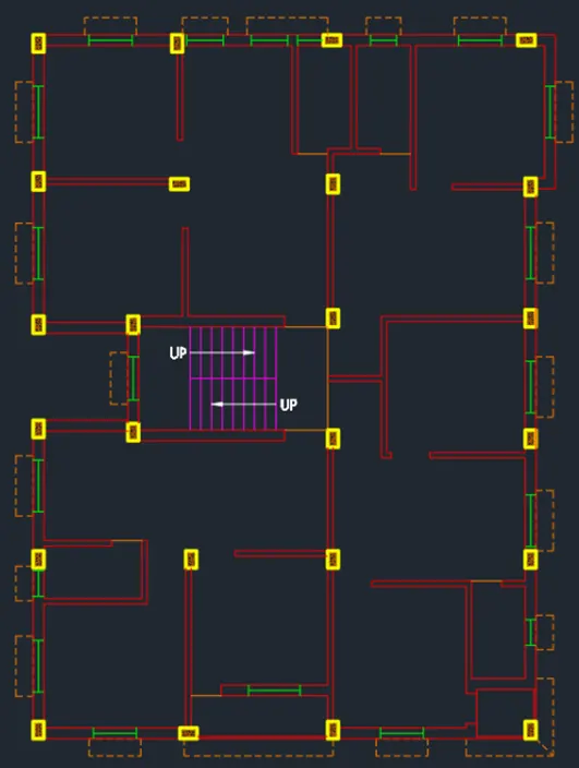
Provides the dimension and text required in the drawing
Use dimlinear to provide dimension and utilize dimcontinue for better progress
Apply dimension breaks in places required
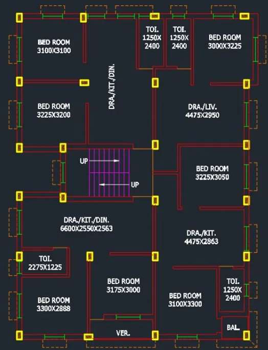
Use dtext command to provide the texts. Text height is 250mm
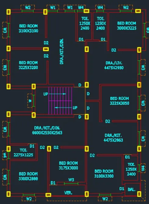
Add the text designated for the doors and windows
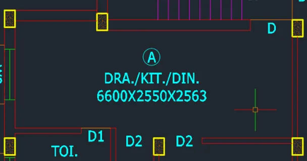
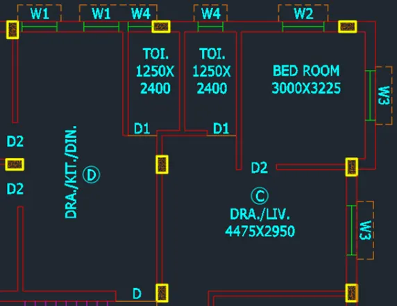
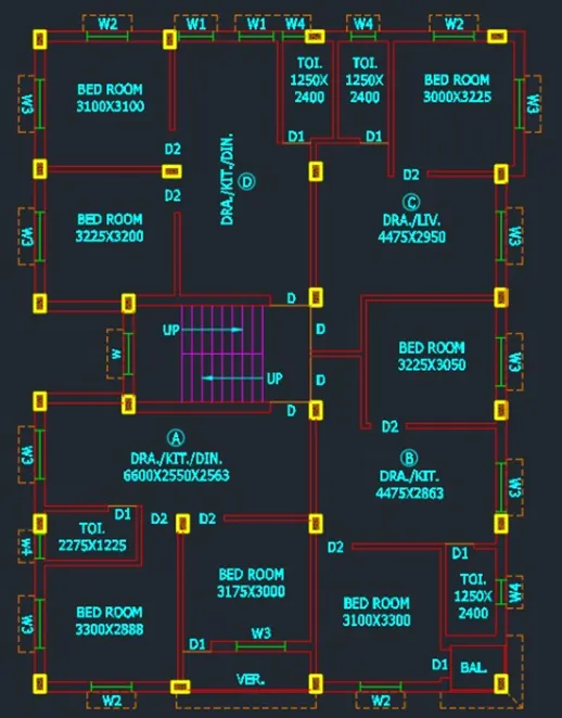
Now add the dimensions use dimbreak command to avaiod intersecting lines
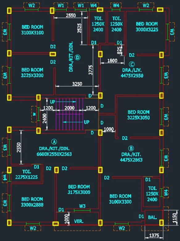
Floor plan
-------> Proceed with section A-A
Project section AA from plan drawing. Use vertical XLINE or ray tool. Then create a horizontal line to act as the base of the elevation. This will be the Ground level.Beam height is 350mm
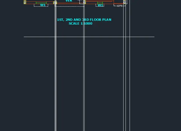
Use the offset command to project the given elevations. LArge the stair first to avoid confusion. Then sketch the column according to first projected line
Add the dimension for reference
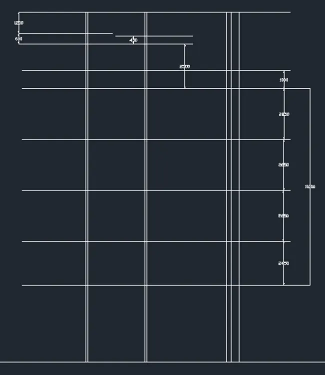
Project the Ground slab then sktech the columns. Trim the excess lines and create the boundaries
Complete the sidewall sketch and add beams where required
Slab thickness is 115mm. Sketch the at all elevations
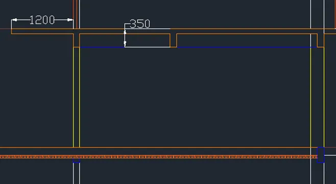
Continue one by one per elevation.Proceed the rooftop sketch and draw the tank as shown.Adjust the tank dimension and add the top opening.Proceed with the stairs. Consider teh given rise. Change lines to hidden line for those on the other side
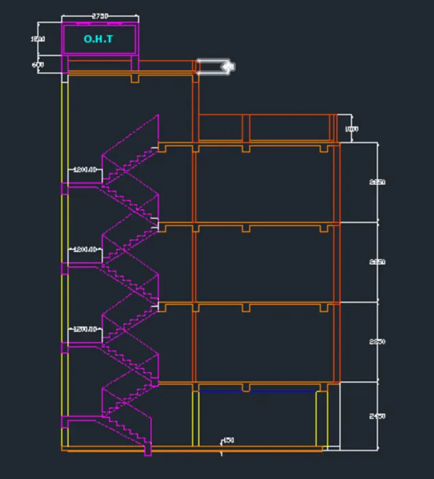
Add the side windows when adding the canopy
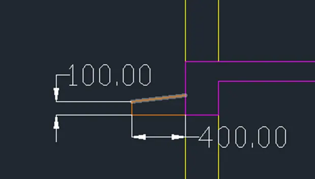
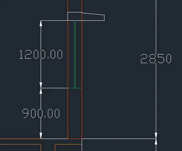
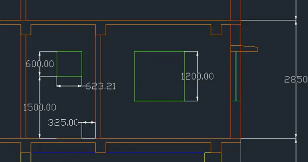
Add the dimensions. Use dimlinear to provide the dimesnsion
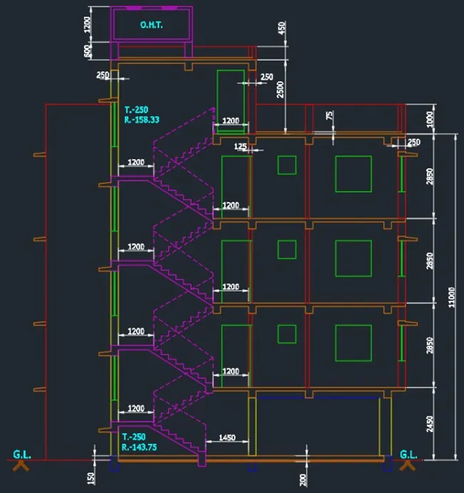
Add the necessary texts in the sketch using dtext command
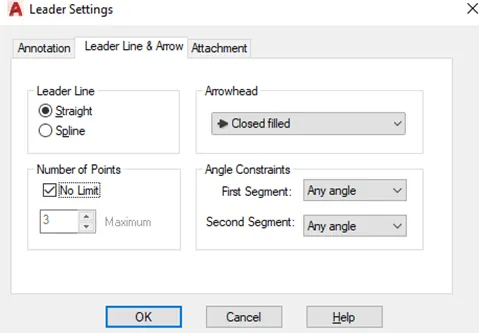
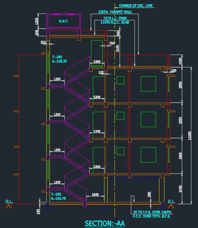
Add leaders for necessary texts using the leader command or use the Mleader command to add leadres with text
(Section A-A)
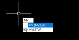
--------->Proceed with the layout . Go to the layout view and create the views using MVIEW command
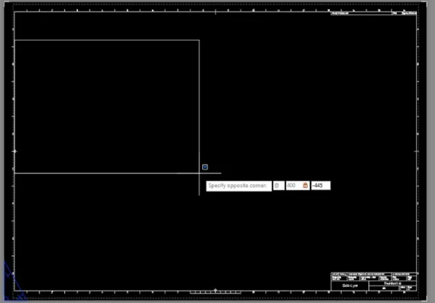

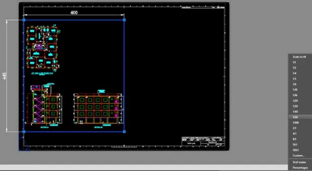
Double click inside the view to move align the object inside
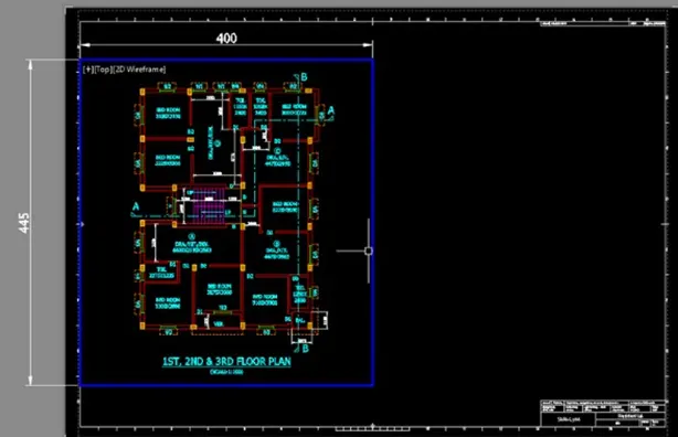
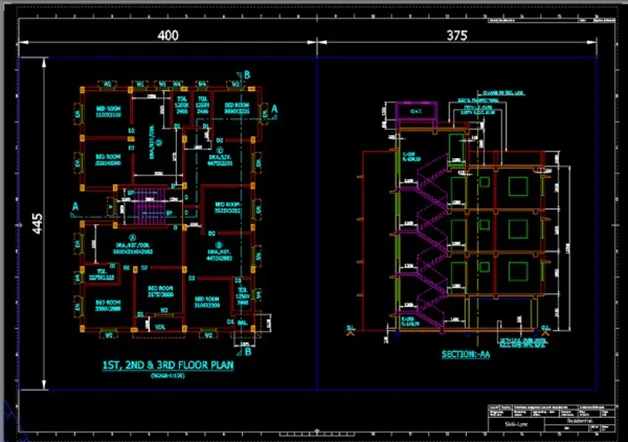
Then take a plot
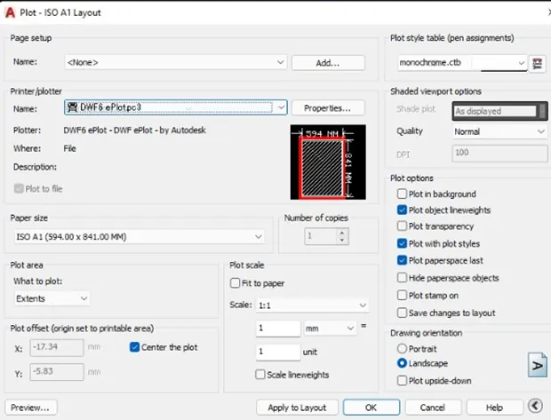
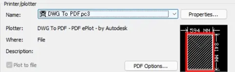
You can change printer to DWG to PDF to ceate PDF file
RESULT:

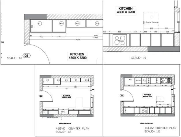
Create a layout of the kitchen drawn in challenge 9 as shown in figure. Use the scale as shown in the figure. Use size page for the layout take a plot
PROCEDURE:
Create the inside boundary using rectangle command. Offset the by 230mm outside to create the wall thicknes
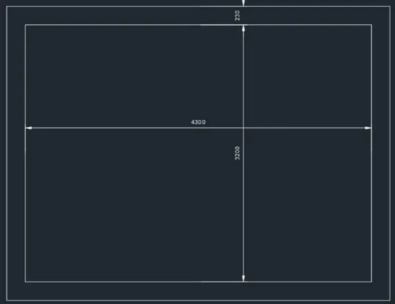
Explode the rectangles.Offset to make the opening boundary and trim
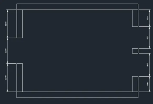
Create the hatching boundaries
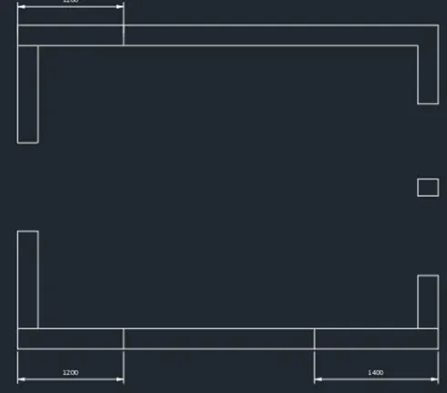
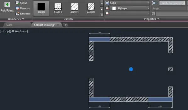
Hatch the wall using "Pick internal points" and edit using the hatch tab on top of the interface or the properties tab
Create the door. use polylines,rectangles and circle. Utilize mirror tool as well
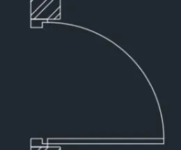
Proceed with the window sketch. Use the same tools used in creatingthe door
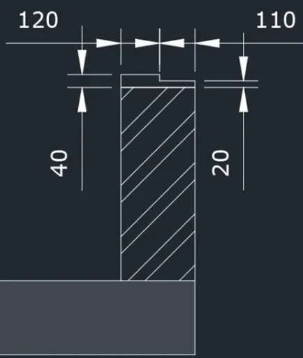
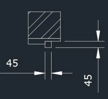
Join the lines to close the window
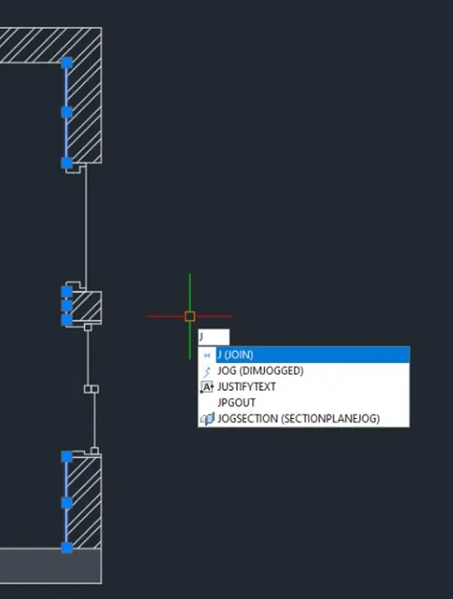
Duplicate the plan for above and below counter
--->Proceed with below the counter plan
Create lines,trim lines and fillet corners with radius 100. Change linetype to hidden. Change line scale in properties tab to show the lines
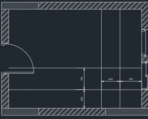
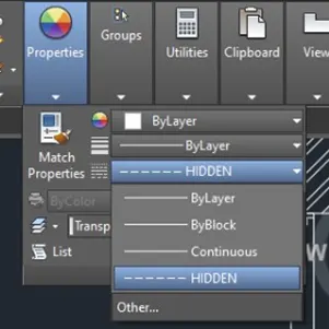
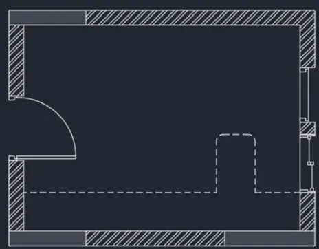
Create the lines for the intersection.Use line and copy tool
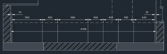
To create dimensions, use dimlinear command and dimmcontinue for easy progress
Adjustements are provided to accomodate the 4300 inner dimensions
Offset lines to create depth.Use trim to cut unnecessary lines
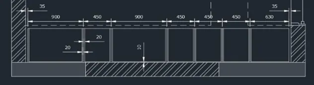
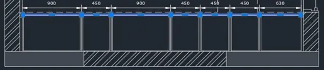
Add the rectangle object at the corners and sletch the door using rectangle and move tool. Utilize the sketch tool to for easy progress. Use 10mm spacing for the doors and 20mm thickness
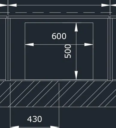
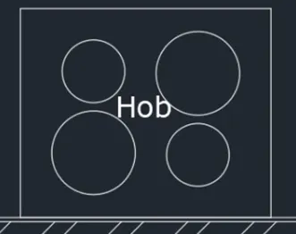
Create the HOb sketch. Use rectangle with 600x500 dimension. Circles with diameter of 200 and 150
Turn on Geometric center in the Osnap settings to check the center of the rectangle
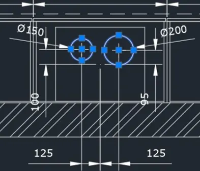
Use mirror with center of the rectangle as mirror plane to dumplicate the objects
Then mirror again to invert objets
Use dtext to add the text object
Proceed with the top part. Create boundary lines using line tools
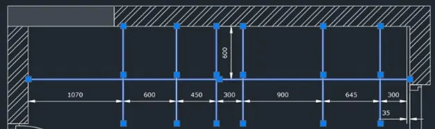
Trim the lines and add line objects to enclose the boundaries
Vertical line thickness is 20mm both sides. The top line 10mm and 50mm for the bottom line
Change the outer bottom line to hidden line. Use match properties (ma) command for easy progress
Trim unnecessary lines to finish
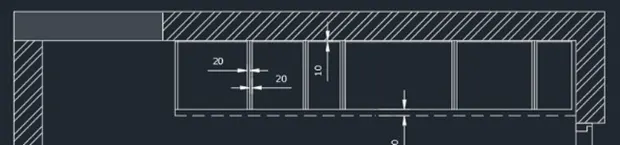
Create therectangle on the lower right side
Create the doors with 20mm thickness and 10mm spacing same as the first one
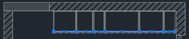
Add the inside objects using circle,rectangle,copy,text and fillet tool
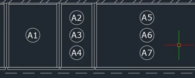
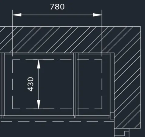
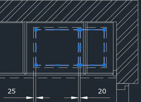
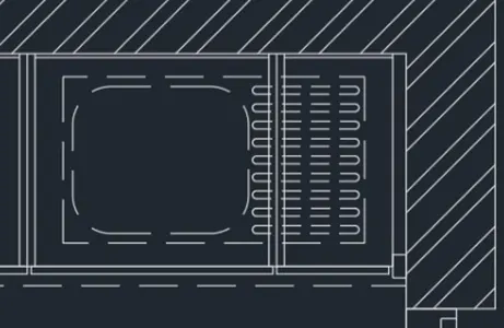
Use rectangle and lines for the fridge object. Use circle tool as cell for the corner opeing
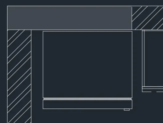
Add the text and finish
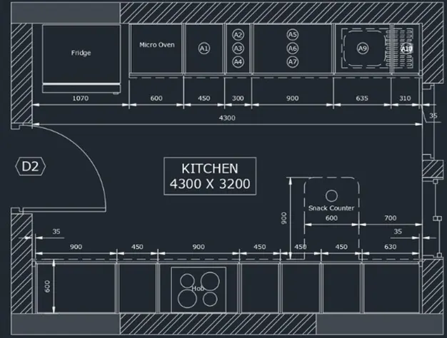
-------> Proceed with the above counter
Copy any relative lines from below to above plan. Change line type as appropriate
Add the border lines for the below part. Trim the line appropriately
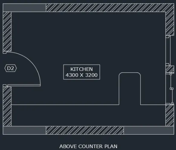
Create the cabinet walls using offset and trim tool. Thickness is 20mm. Bottom part is 10mm
Trim unnecessary lines
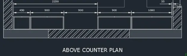
Create the chimney as below
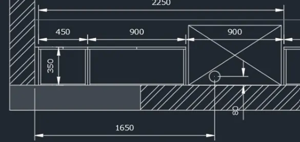
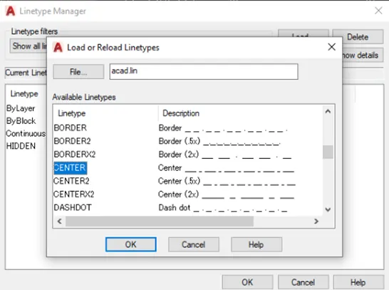
Add Centerline in the Linetype manager
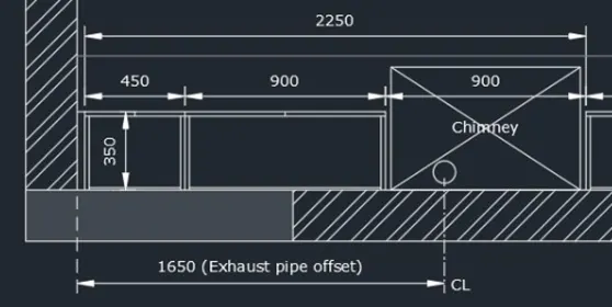
Explode the dimension line and edit as below. Add the appropriate texts using dtext command
Proceed with above objects. Create boundary lines. trim the lines appropriately
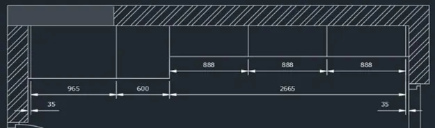
Create the walls. Thickness=20mm Use offset,copy and trim tools.
Trim and add the rectangles and add text
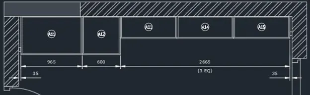
Add the missing dimensions using dimlinear to finish
------------> Now proceed to the layout and plotting

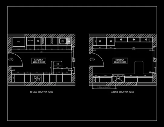
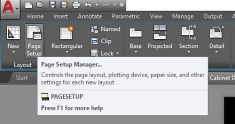
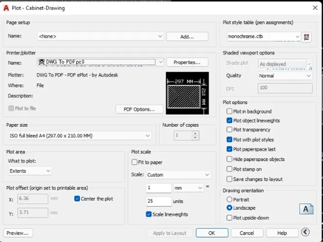
Go to page setup to setup the paper
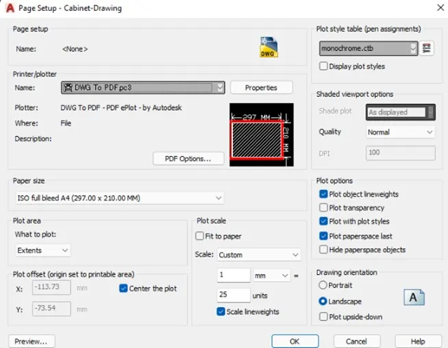
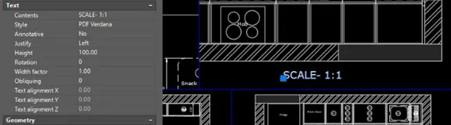
Use 1:25 as plot scale. You can change arrangement as required
Create the views using MNIEW comman
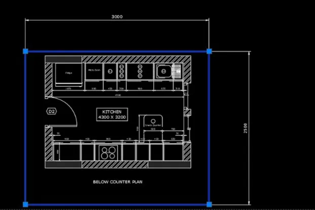
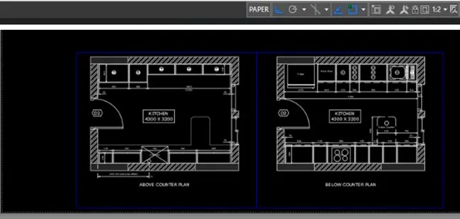
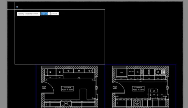
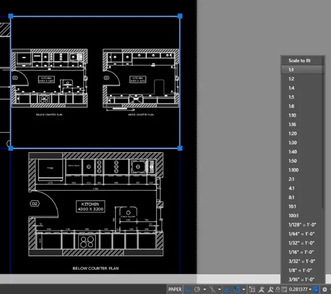
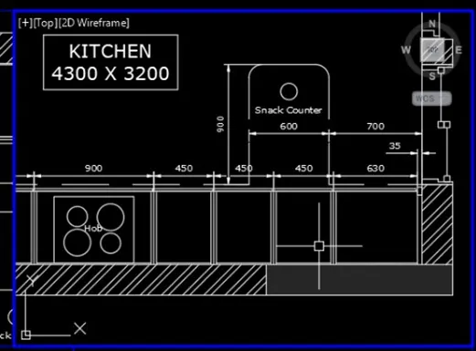
Add the texts using dtext command
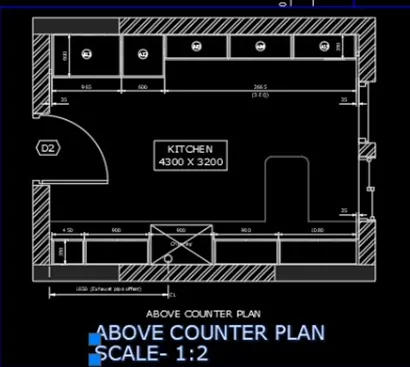
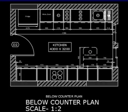
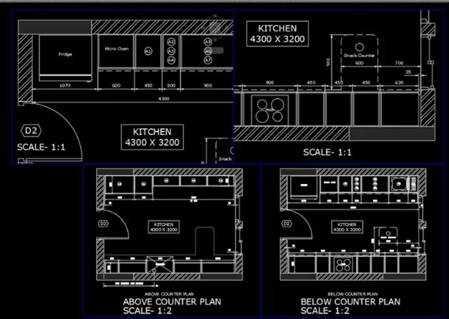
Take a plot
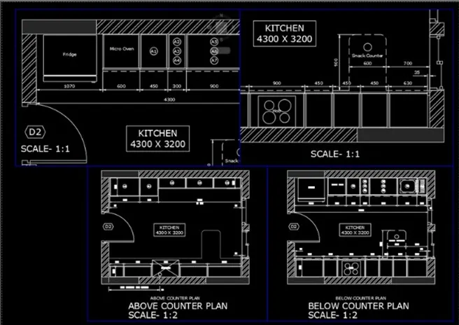
Result
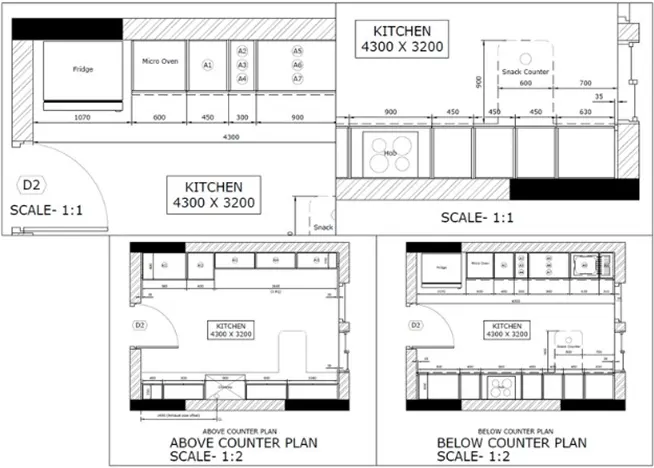
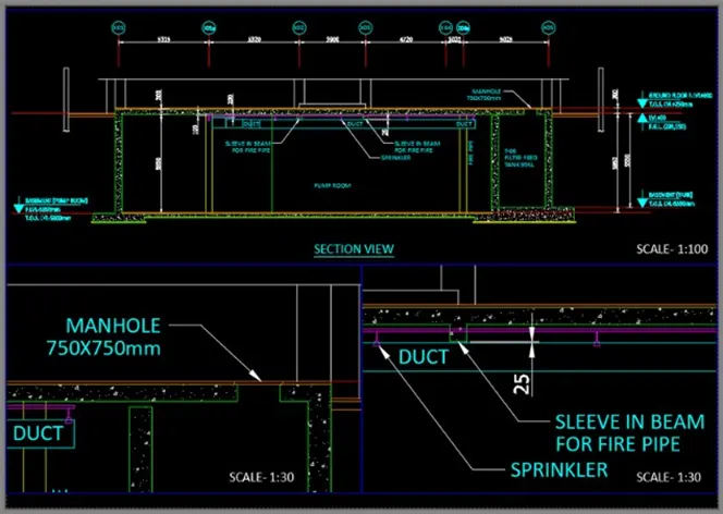
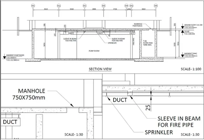
Create a layout of the section created in challeneg 9 use scale as mentioned in the Use MV command create multiple viwports Take plot
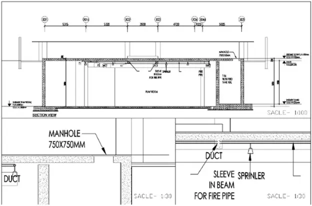
Ans:
PROCEDURE:
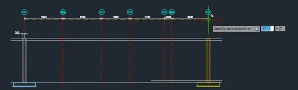
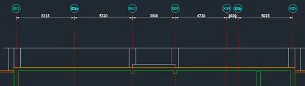
Create the borders using lines. Start from ground level
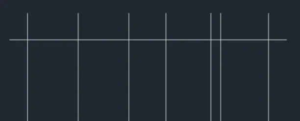
Add the grid tags and dimensions
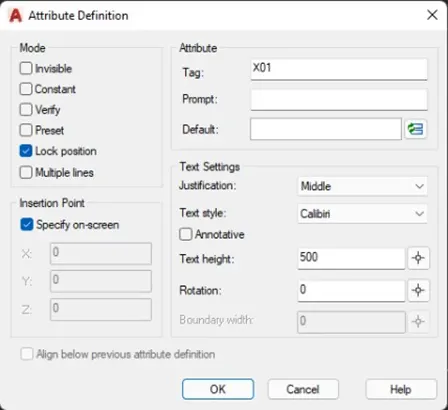
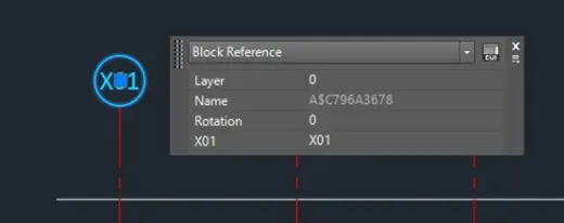

Add the borders of wall
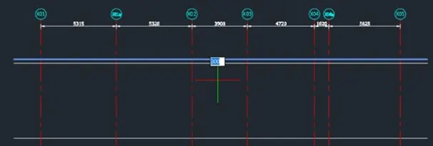
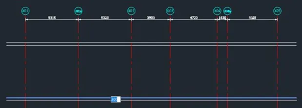
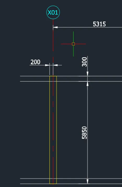
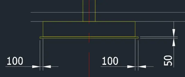
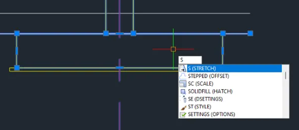
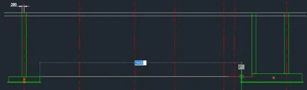
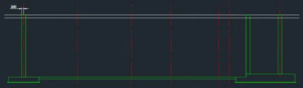
Trim the unnecessary lines
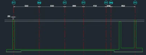
Do the same procedure for the top slab
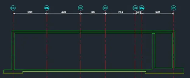
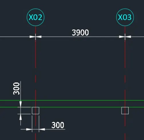
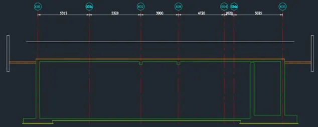
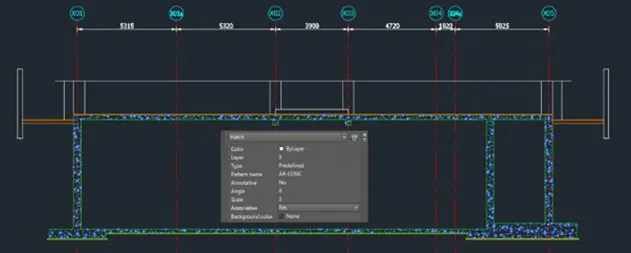
Add the wall hatch
Add lines inside
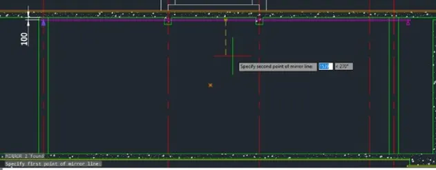
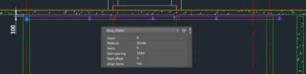
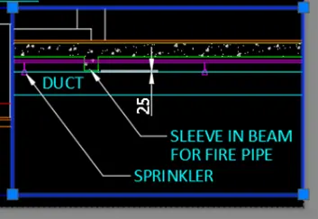
Create the duct
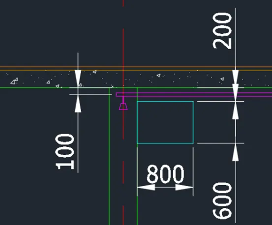
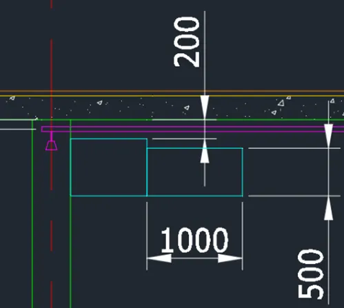
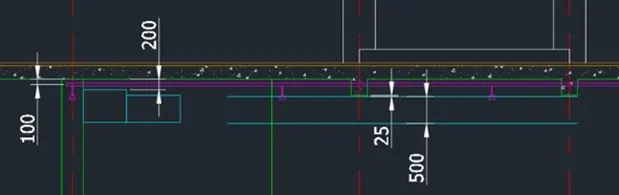
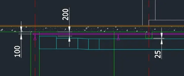
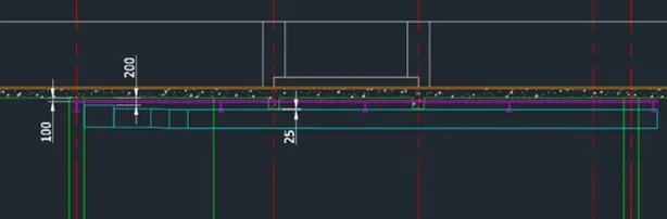
Add necessary texts and dimensions using dimlinear,dtext,move, and copy tool
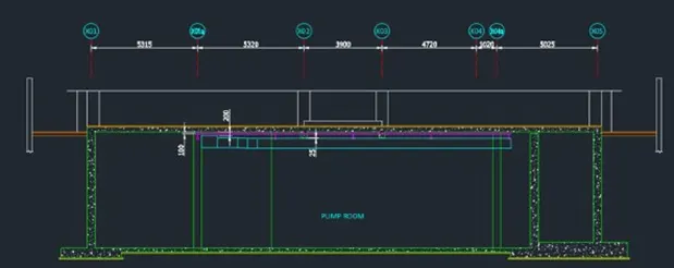

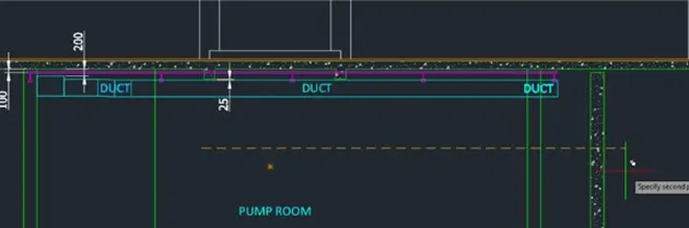
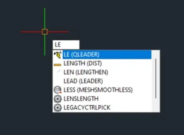
Add arrows using the leader command
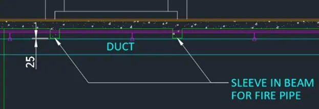
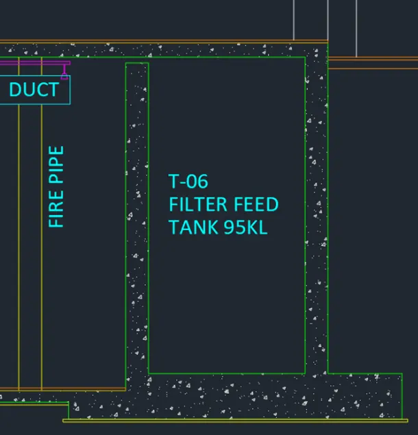
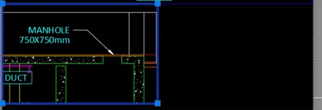
Add the manhole use line and trim command
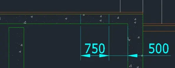
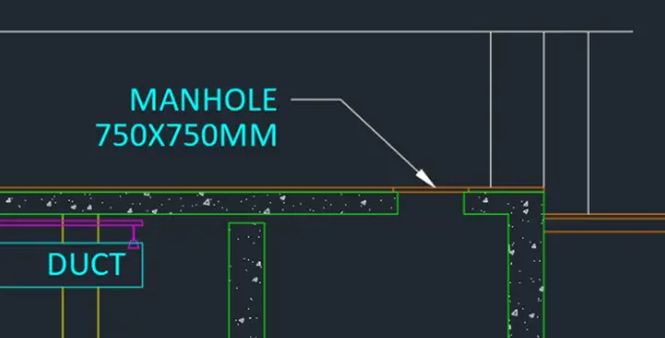
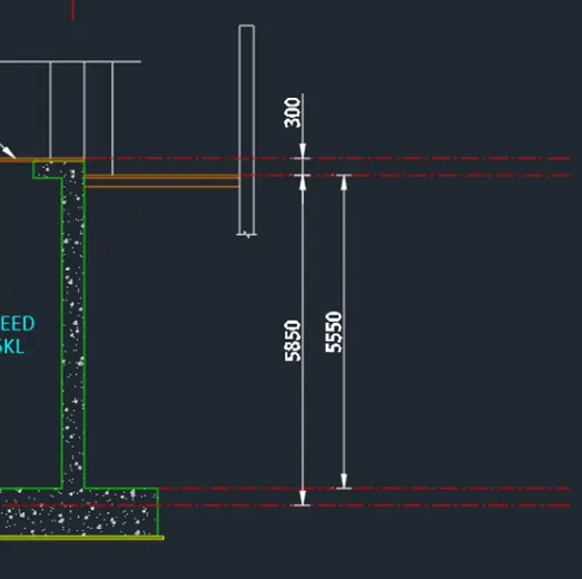
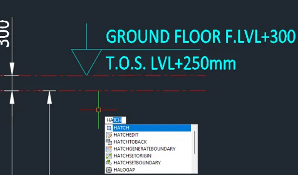
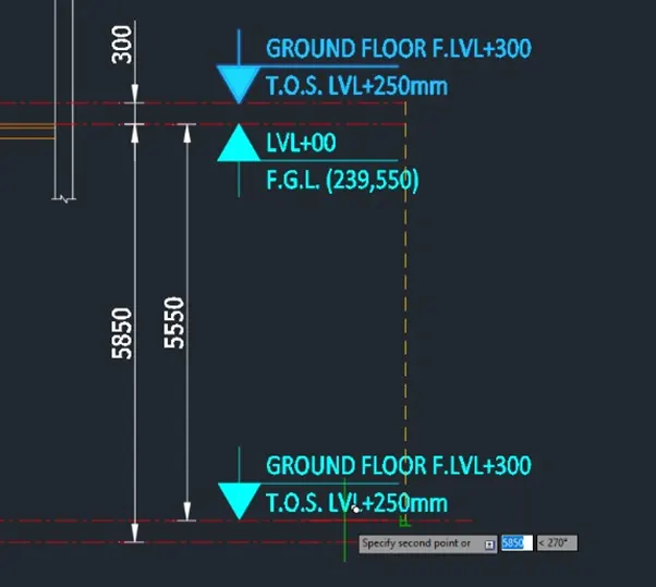
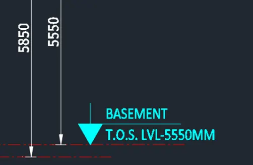
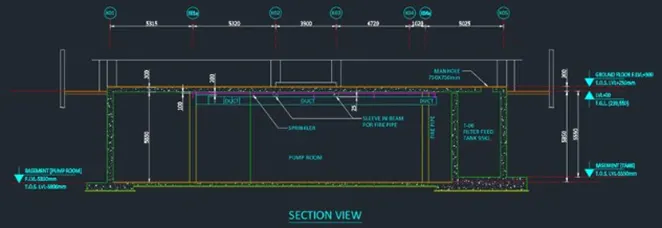
------>Proceed with the layout
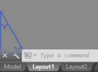
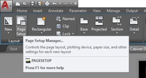
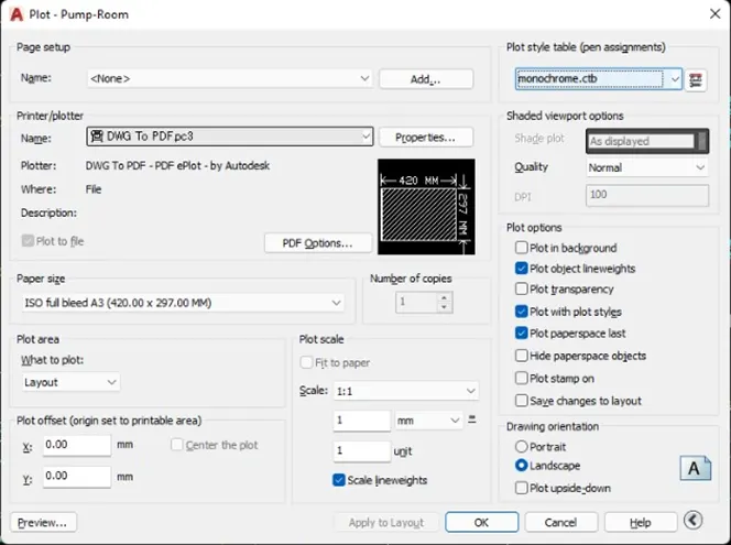
Go to page setup to setup the paper
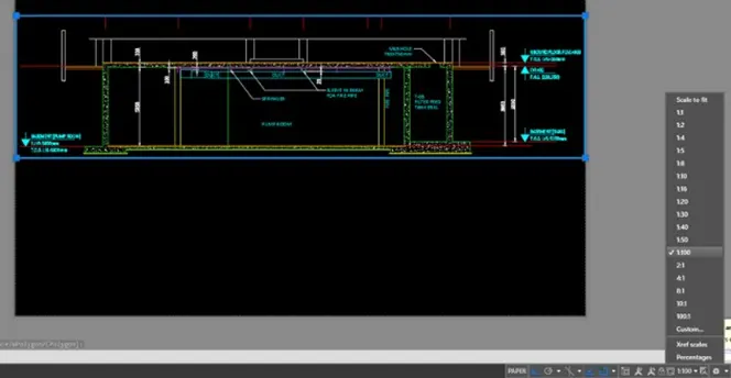
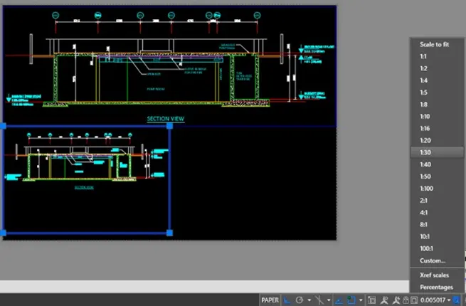
Use 1:1 as plot scale you can change arrangemenyt as required
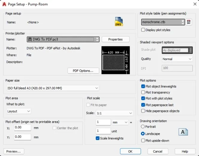
Create the views using MVIEW command
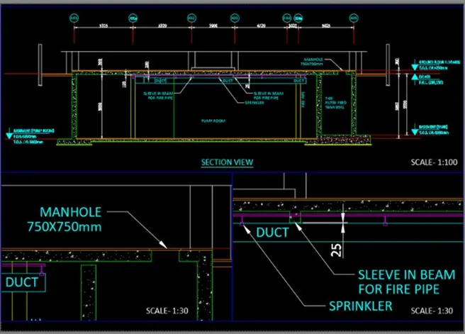
Take a Plot
RESULT:
CONCLUSION:
The MVIEW command of the AutoCAD software is a useful way to create multiple views of different scale in the layout. IT helps the user to manipulate certain sizes to make use of the actual size of the paper. the AutoCAd software also provide ceratin templates that will help the user provide title blocks that can be used as reference in a project