Creation of Multiple viewports, Scaling the drawing and setting in Template in AutoCad
Question 1. Create a layout of the Plan and Section A of the project in Challenges 7, using the template Tutorial-mArch.dwt in a scale as given in the Figure. Use the MV command to create the viewport of the size as shown in Figure. Also, use ATTEDIT command to edit the information in the title block. Use A1 size for the layout. Take a plot.
AIM: To create a layout of the Plan and Section A of the project in Challenges 7, using the template Tutorial-mArch.dwt in a scale as given in the Figure. Use the MV command to create the viewport of the size as shown in Figure. Also, use ATTEDIT command to edit the information in the title block. Use A1 size for the layout. Take a plot.
INTRODUCTION: In this question we will be able to understand the concept of creating a layout of the Plan and Section A of the previous challenge project we we have created in the challenge 7. It is a G+1 residential building. In this section we will be able to understand the concept of layout using the various commands like MV to create viewport and ATTEDIT command to edit the information in the title block.
PROCEDURE:
- So in order to create a layout of the plan and the section A of the previous project in challenge 7. We first need to open the AutoCAD software 2019.
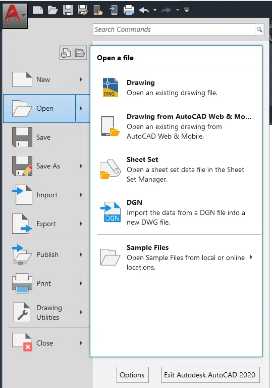
- After opening the AutoCAD software we need to open the project of challenge 7. To open the project we need to click on the Open option in the AutoCAD after that click on the Drawing option as shown in the below figure:
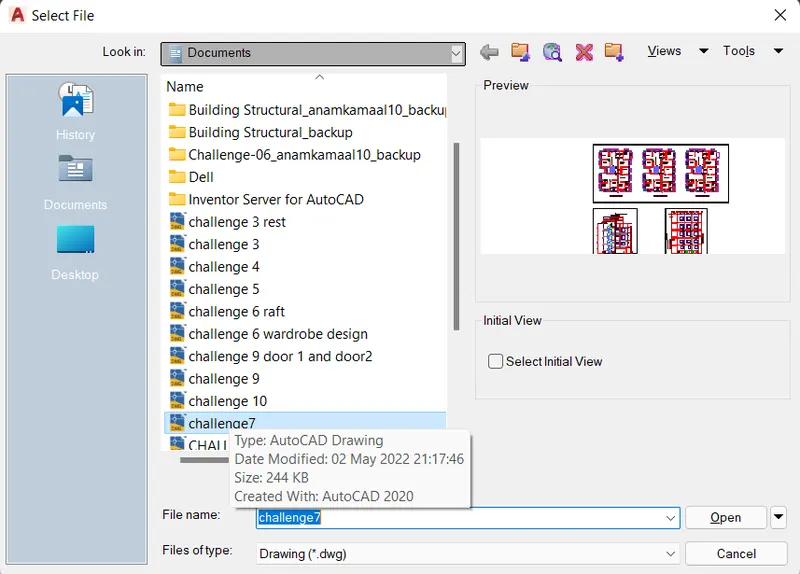
- After clicking on the option Open and the drawing a new dialouge box appears on the screen titled as Select file. From there we can choose the desired file. So i have choosen file named "Challenge 7" and then click on OK. As shown in the below image:
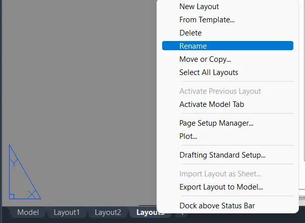
- Now we have to create the new layout for this project so in order to create a new layout go to the bottom left corner of the Autocad screen. In that corner we have option named Model,layout1 and then layout 2 and there is a plus(+) sign click on that sign it is a sign for creating a new layout as shown in the below figure:

- After clicking on that sign rename it as Floor Plan and Section AA as shown in the below figure:

- After doing that create a model view by typing V in the command line and then press Enter.
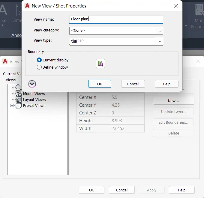
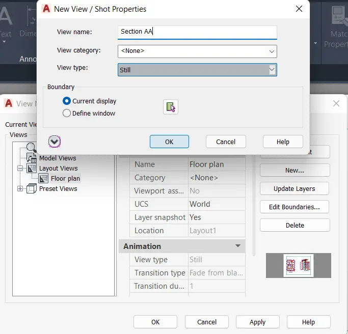
- A new dialouge box opens titled as View manager in that dialouge box click on the modify option a new window tilttled as New View/Shot Properties opens up in that window give the View name as the Floor plan and set boundary as Current display and then press OK. Model view for the floor plan has been created.Just as shown in the below figure:
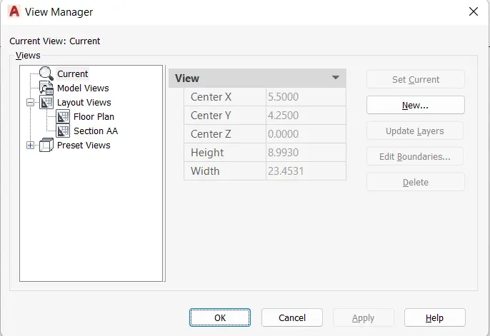
- Now do the same procedure for the Section AA as shown in the below figure:
- After creating the model view,now we have to do the page setup for this viewport.
- So for doing the pagesetup just type Pagesetup in the command line and then press Enter.
- A new dialouge box appears as shown in the below figure:
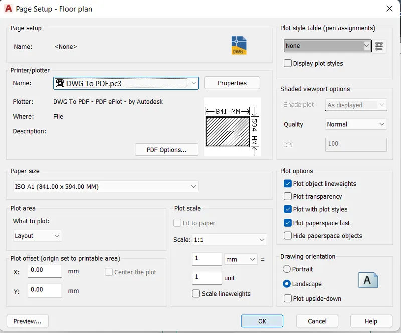
- Choose the paper size as A1 and then adjust the other settins like printer/plotter name plot style etc and then click on the OK button.
- Now in the command line type Layout and then press Enter. From there click on the option template as shown in the below figure:
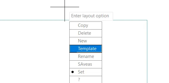
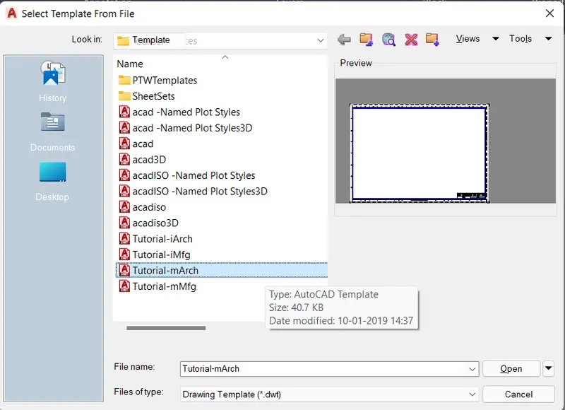
- After clicking on the template option a new dialouge box opens named as select template from file in that dialouge box click on the option "Tutorial mArch" after that click on the option open as shown in the below figure:
- A new layout has been created as shown below:
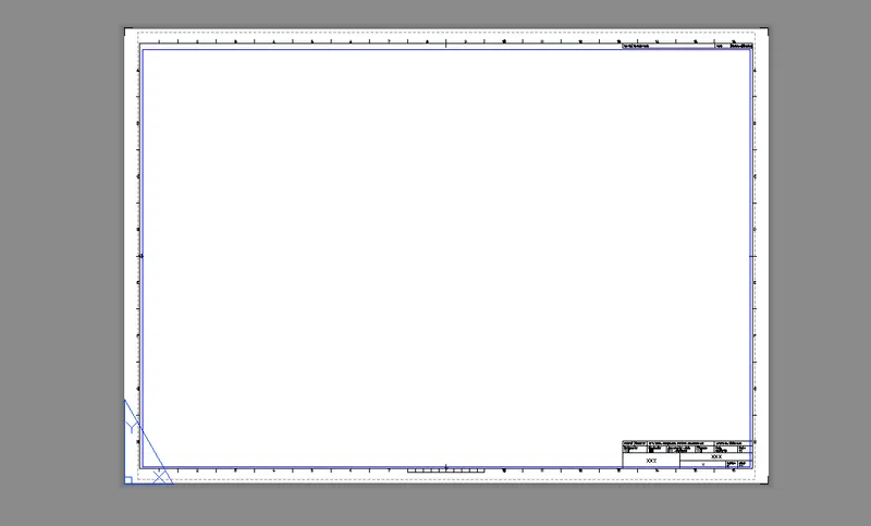
- After creating the template we have to insert the First floor plan and the Section AA in this template.
- So for doing so we need to type Insert in the command line and then press Enter.
- After typing the insert a new box opens from that window drag the image into the template of first floor plan and the section AA just as shown in the below figure:
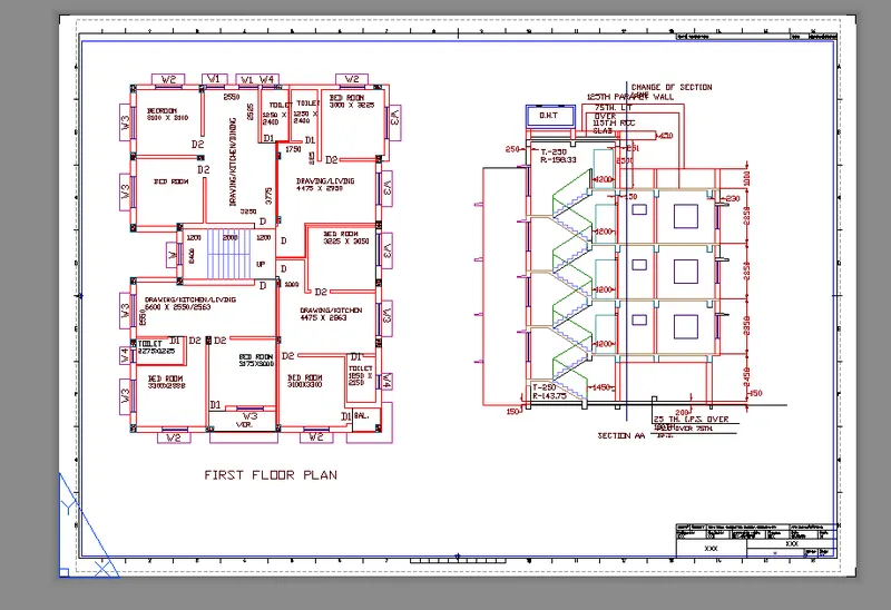
- After that now type page setup in the command line and then press Enter.
- Now we have to create the view ports in this section.
- For creating viewports go to the view ribbon from that click on the option viewport and then click on the 2 viewports as we need two viewports for this question as we can see in the below image:
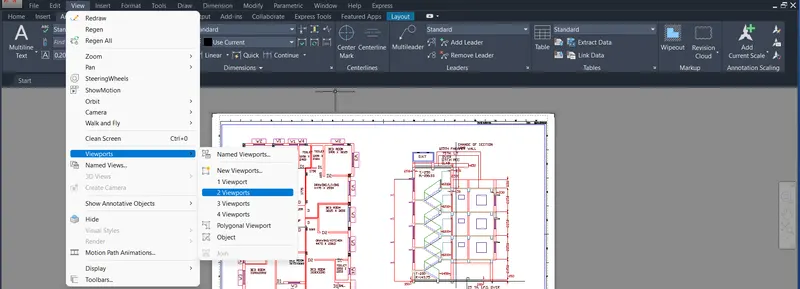
- After selection the numbers of the viewports autoCAD asks for the direction of creating the viewports as if we need to create the viewport in the horizontal direction or in the vertical direction. In this question we need Vertical direction so click on the vertical and then it will ask you to specify the first point so specify the first point and the specify the end point and the click enter now the 2 viewports have been created as shown in the below figure:
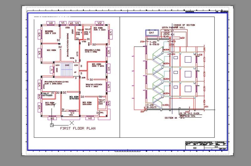
- After doing this we have to edit the attributes in this section,so first of all we need to type ATTEDIT in the command line an new dialouge box appears in that dialouge box edit the attributes and then click ok. With editing the attributes the viewports have been created using the different commands like MV,ATTEDIT,PS etc.
- Result has been shown in the below figure:
Question 2. Create a layout of the Kitchen drawn in Challenge 9 as shown in Figure. Use the scale as shown in the Figure. Use A4 Size page for the layout. Take a plot.
AIM: To create a layout of the Kitchen of the project in Challenges 9.Use the MV command to create the viewport of the size as shown in Figure.Use A4 size for the layout. Take a plot.
INTRODUCTION: In this question we will be able to understand the concept of creating a layout of the Kitchen plan of the previous challenge project we we have created in the challenge 9.In this section we will be able to understand the concept of layout using the various commands like MV to create viewport,MS to zoom in and zoom out in the viewport,pagesetup etc.
PROCEDURE:
- So in order to create a layout of the Kitchen plan of the previous project in challenge 9. We first need to open the AutoCAD software 2020.
- After opening the AutoCAD software we need to open the project of challenge 9. To open the project we need to click on the Open option in the AutoCAD after that click on the Drawing option as shown in the below figure:
- After clicking on the option Open and the drawing a new dialouge box appears on the screen titled as Select file. From there we can choose the desired file. So i have choosen file named "Challenge 9" and then click on OK. As shown in the below image:
- Now we have to create the new layout for this project so in order to create a new layout go to the bottom left corner of the Autocad screen. In that corner we have option named Model,layout1 and then layout 2 and there is a plus(+) sign click on that sign it is a sign for creating a new layout as shown in the below figure:
- After clicking on that sign rename it as Floor Plan and Section AA as shown in the below figure:
- After doing that create a model view by typing V in the command line and then press Enter.
- A new dialouge box opens titled as View manager in that dialouge box click on the modify option a new window tilttled as New View/Shot Properties opens up in that window give the View name as the kitchen plan and set boundary as Current display and then press OK. Model view for the floor plan has been created.Just as shown in the below figure:
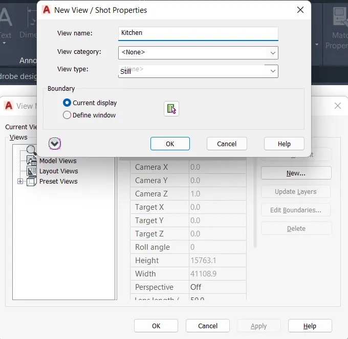
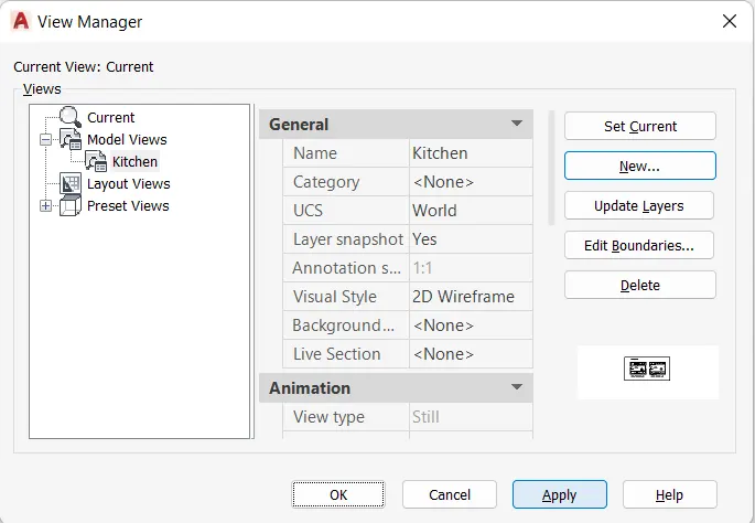
- After creating the model view,now we have to do the page setup for this viewport.
- So for doing the pagesetup just type Pagesetup in the command line and then press Enter.
- A new dialouge box appears as shown in the below figure:
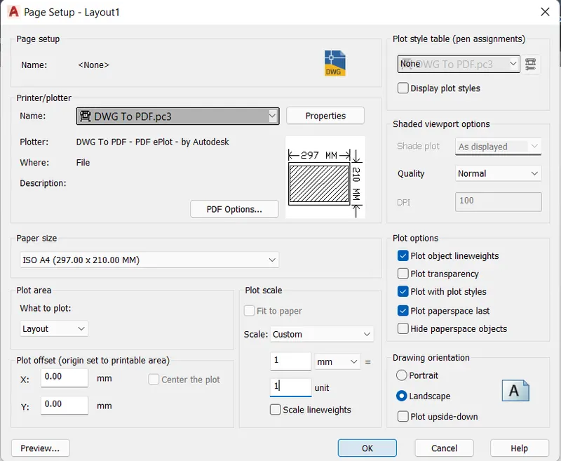
- Choose the paper size as A4 and then adjust the other settings like printer/plotter name plot style etc and then click on the OK button.
- After editing the pagesetup choose the MV command.
- For doing so we have to type MV in the command line and then press Enter.
- Now we have to create the view ports.
- Now we have to create the view ports in this section.
- For creating viewports go to the view ribbon from that click on the option viewport and then click on the 2 viewports as we need two viewports for this question as we can see in the below image:
- Now specify the viewport as 4 and the view port arrangement as Horizontal.
- After selection the numbers of the viewports autoCAD asks for the direction of creating the viewports as if we need to create the viewport in the horizontal direction or in the vertical direction. In this question we need Vertical direction so click on the vertical and then it will ask you to specify the first point so specify the first point and the specify the end point and the click enter now the 4 viewports have been created.
- And use the MS command to zoom in and zoon out the views.
- Just type MS in the command line and then press Enter.
- The viewports have been created using the different commands like MV,ATTEDIT,PS etc.
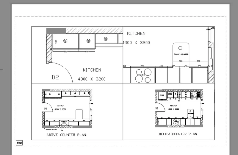
- Now we have to create the dimension and the text in this section.
- For doing so we have to type Dtext and press Enter.
- After that specify the point to edit the text and give the text height and the angle and type the text.
- The dimensioning and the text have been created as shown in the below figure:
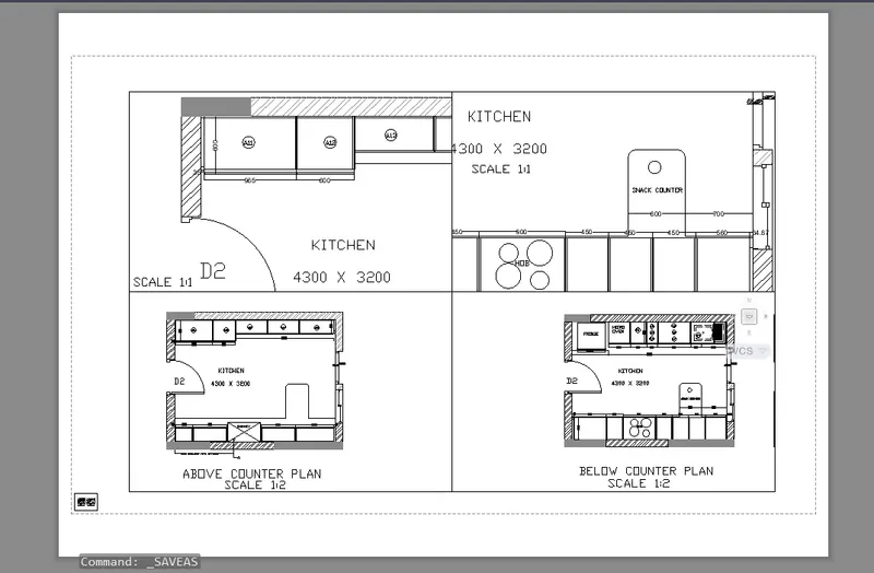
- Result has been shown in the below figure:
Question 3. Create a layout of the section created in Challenges 9.
Use scale as mentioned in the Figure. Use MV command create multiple viewports. Take a plot.
AIM: To create a layout section of the project in Challenges 9.Use the MV command to create the viewport of the size as shown in Figure.Use A1 size for the layout. Take a plot.
INTRODUCTION: In this question we will be able to understand the concept of creating a layout of the layout of the sectoin of the previous challenge project we we have created in the challenge 9.In this section we will be able to understand the concept of layout using the various commands like MV to create viewport,MS to zoom in and zoom out in the viewport,pagesetup etc.
PROCEDURE:
- So in order to create a layout of the layout section of the previous project in challenge 9. We first need to open the AutoCAD software 2020.
- After opening the AutoCAD software we need to open the project of challenge 9. To open the project we need to click on the Open option in the AutoCAD after that click on the Drawing option as shown in the below figure:
- After clicking on the option Open and the drawing a new dialouge box appears on the screen titled as Select file. From there we can choose the desired file. So i have choosen file named "Challenge 9" and then click on OK. As shown in the below image:
- Now we have to create the new layout for this project so in order to create a new layout go to the bottom left corner of the Autocad screen. In that corner we have option named Model,layout1 and then layout 2 and there is a plus(+) sign click on that sign it is a sign for creating a new layout as shown in the below figure:
- After clicking on that sign rename it as Layout section as shown in the below figure:
- After doing that create a model view by typing V in the command line and then press Enter.
- A new dialouge box opens titled as View manager in that dialouge box click on the modify option a new window tilttled as New View/Shot Properties opens up in that window give the View name as the section for industrial plan and set boundary as Current display and then press OK. Model view for the floor plan has been created.Just as shown in the below figure:
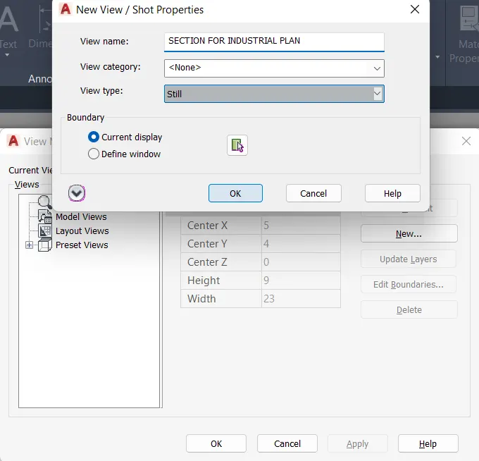
- After creating the model view,now we have to do the page setup for this viewport.
- So for doing the pagesetup just type Pagesetup in the command line and then press Enter.
- A new dialouge box appears as shown in the below figure:
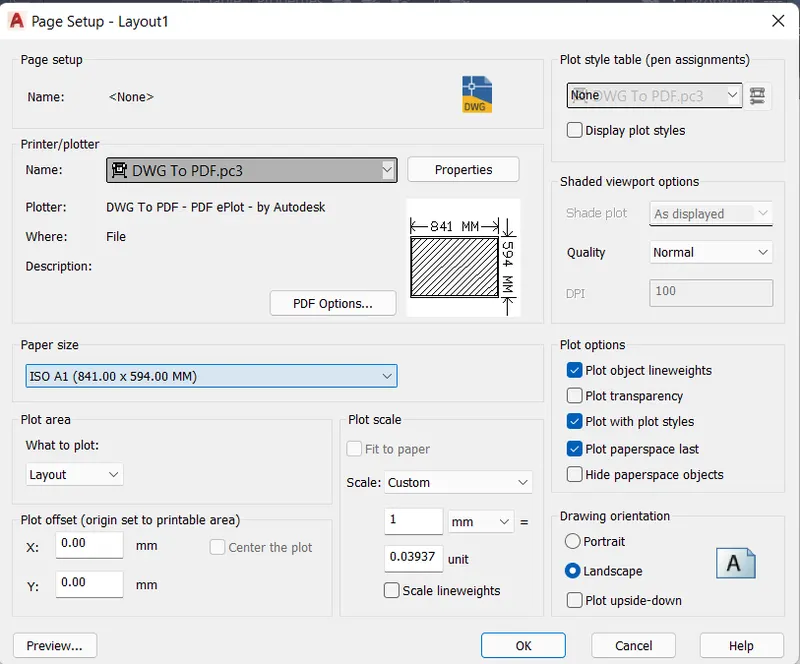
- Choose the paper size as A1 and then adjust the other settings like printer/plotter name plot style etc and then click on the OK button.
- After editing the pagesetup choose the MV command.
- For doing so we have to type MV in the command line and then press Enter.
- Now we have to create the view ports.
- Now we have to create the view ports in this section.
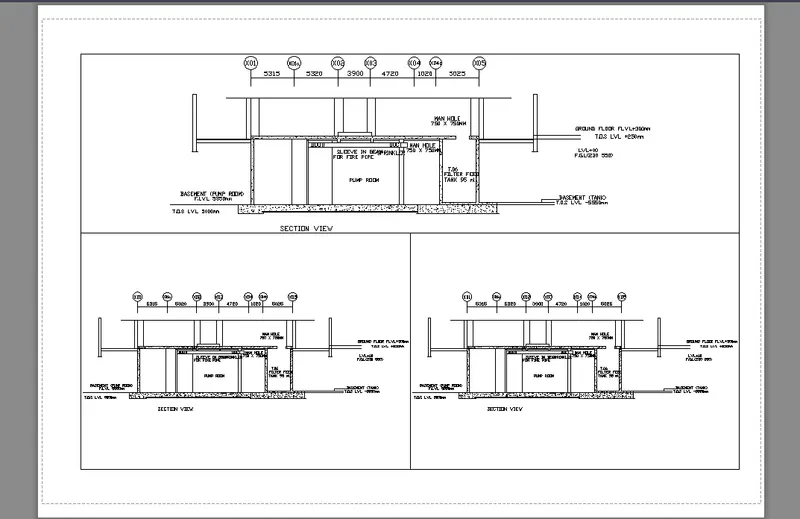
- Now specify the viewport as 3 and the view port arrangement as 2 Horizontal and 1 vertical.
- After selection the numbers of the viewports autoCAD asks for the direction of creating the viewports as if we need to create the viewport in the horizontal direction or in the vertical direction. In this question we need Vertical direction so click on the vertical and then it will ask you to specify the first point so specify the first point and the specify the end point and the click enter now the 3 viewports have been created as shown in the below figure:
- And use the MS command to zoom in and zoon out the views.
- Just type MS in the command line and then press Enter.
- The viewports have been created using the different commands like MV,ATTEDIT,PS etc.
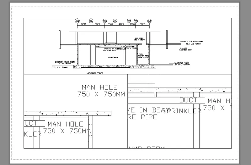
- Now we have to create the dimension and the text in this section.
- For doing so we have to type Dtext and press Enter.
- After that specify the point to edit the text and give the text height and the angle and type the text.
- The dimensioning and the text have been created as shown in the below figure:
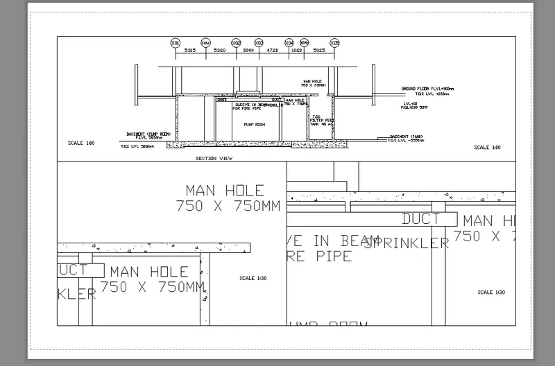
- Result has been shown in the below figure:
RESULT:
(a) Floor Plan and Section A:
(b) Kitchen:
(c) Industrial layout section: