Creation of geometries by Coordinate system methods using AutoCad
AIM:- To draw the geometric figures by using
1. Absolute cordinate method
2. Relative coordinate method
a. Relative rectangle method
b. Relative polar coordinate method
Apparaturs:- Auto cadd software
Introduction:-
Coordinates systems:- coordinate system is a system where numbers are used to detemine the unique position of points and/or other geometics elements.
The various coordinate systems are:-
- Absolute coordinate system: in this system all points are established at some distance in the x &y axis from a common orgin
- Relative coordinate system:- the location of a relative coordinate is defined by its distance from a reference point. in auto cadd when using this system the first point of the drawing/geometry is always absolute, i.e it is established with respect to origin (0,0) and then all the successive positions are established with respect to their preceding point. This system is futher classified as-
- Relative rectangle coordinates: it is a coordinate system that specifes each point by a pair of numerical coordinates in the X-axis and Y-axis. in this system the points succeding the first point are typed in as @x,y in the command line.
- Relative polar coordinate: this system specifies the distance and angle of a particular point . in relative polar coordinate system, points aare established by typing @distance
- Direct distance entry method: it is another popular method used for drawing differnt shapes/geometries in Autocadd. direct distance entry method enables the user to draw an object by simply pointing the cursor in the desired in the command line.
PROCEDURE:
- Go to start menu, select auto cad 2022.
- click on the start drawing
- in the command line type in: STARTUP (ENTER)
- Enter new value of startup:1
- Go to the appilcaton menu and select new
- in the 'create new Drawing' dialog box, we select the 'imperical system' in the 'start form scratch' option
- Next we select the 'decimal' unit system from the 'advanced steup' option
- set limits by entering LIMITS in the command tab. The lower- left corner is specified as 0,0 and the upper right corner is specified as 100,100
P1:-
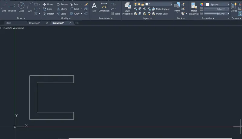
A. Using absolute coordinate system
- Select the line tool by entering LINE command in the command tab.
- Specify the starting coordinate of point 1as 2,1 in the command line
- Specifiy the next coordinate of point 2 as 8,1 in the command line.
- Specifiy the next coordinate of point 3 as 8,2in the command line.
- Specifiy the next coordinate of point 4 as 3,2 in the command line.
- Specifiy the next coordinate of point 5 as 3,6 in the command line.
- Specifiy the next coordinate of point 6 as 8,6 in the command line.
- Specifiy the next coordinate of point 7as 8,7 in the command line.
- Specifiy the next coordinate of point 8 as 2,7 in the command line.
- click close on the command line.
B. Using Relative Rectangular coordinate syatem.
- select the line tool by entering LINE command in the command tab.
- Specify the starting coordinate of point 1 as 2,1 in the command line
- specific the next coordinate of point 2 as @6,0 in the command line
- specific the next coordinate of point 3 as @0,1 in the command line
- specific the next coordinate of point 4 as @-5,0 in the command line
- specific the next coordinate of point 5 as @0,4 in the command line
- specific the next coordinate of point 6 as @5,0 in the command line
- specific the next coordinate of point 7 as @0,1 in the command line
- specify the next coordinate of point 8 as @-6,0 in the command line
- click close on the command line.
c. using relative polar coordinate system.
- Select the line tool by entering LINE command in the command tab.
- Specify the starting coordinate of the point 1 as 2,1 in the command line.
- Specify the next coordinate of point 2 as @ 6<0 in the command line
- Specify the next coordinate of point 2 as @ 1<90 in the command line
- Specify the next coordinate of point 2 as @ 5<180 in the command line
- Specify the next coordinate of point 2 as @ 4<90 in the command line
- Specify the next coordinate of point 2 as @ 5<0 in the command line
- Specify the next coordinate of point 2 as @ 1<90 in the command line
- Specify the next coordinate of point 2 as @ 6<180 in the command line
- click the Close on the command line.
RESULT:
D. using direct distance entry method.
- Select the line tool by entering LINE command in the command tab.
- Specify the starting coordinate of point as 2,1 in the command line.
- Enter the length of the point 2 as 6 in the command line towards +ve x-axis.
- Enter the length of the point 3 as 1 in the command line towards +ve y-axis
- Enter the length of the point 4 as 5 in the command line towards -ve x-axis
- Enter the length of the point 5 as 4 in the command line towards +ve y-axis
- Enter the length of the point 6 as 5 in the command line towards +ve x-axis
- Enter the length of the point 7 as 1 in the command line towards +ve y-axis
- Enter the length of the point 8 as 6 in the command line towards -ve x-axis
RESULT:
DRAFTING THE GEOMETRY IN P2
A. Using absolute coordinate system
- Select the line tool by entering LINE command in the command tab.
- Specify the starting coordinate of the point 1 as 2,1 in the command line
- Specify the starting coordinate of the point 2 as 5,1 in the command line
- Specify the starting coordinate of the point 3 as 5,5 in the command line
- Specify the starting coordinate of the point 4 as 6,5in the command line
- Specify the starting coordinate of the point 5 as 6,1 in the command line
- Specify the starting coordinate of the point 6 as 9,1 in the command line
- Specify the starting coordinate of the point 7 as 7,8 in the command line
- Specify the starting coordinate of the point 8 as 4,8 in the command line
- click close on the command line.
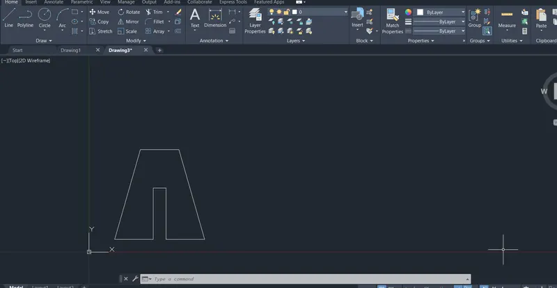
B. Using relative rectangular coordinate system.
- Select the line tool by entering LINE command in the command tab.
- Specify the starting coordinate of the point 1 as 2,1 in the command line.
- Specify the next coordinate of point 2 as @ 3,0 in the command line.
- Specify the next coordinate of point 3 as @ 0,4 in the command line.
- Specify the next coordinate of point 4 as @ 1,0 in the command line.
- Specify the next coordinate of point 5 as @ 0,-4 in the command line.
- Specify the next coordinate of point 6 as @ 3,0 in the command line.
- Specify the next coordinate of point 7 as @ -2,7 in the command line.
- Specify the next coordinate of point 8 as @ -3,0 in the command line.
- click close on the command line.
c. Using Relative polar coordinate system
- Select the line tool by entering LINE command in the command tab.
- Specify the starting coordinate of point 1 as 2,1 in the command line.
- Specify the next coordinate of point 2 as @3<0 in the command line.
- Specify the next coordinate of point 3 as @4<90 in the command line.
- Specify the next coordinate of point 4 as @1<0 in the command line.
- Specify the next coordinate of point 5 as @4<270 in the command line.
- Specify the next coordinate of point 6 as @3<0 in the command line.
- Specify the next coordinate of point 7 as @7<106 in the command line.
- Specify the next coordinate of point 8 as @3<180 in the command line.
- click close on the command line
RESULT:
D. using direct distance entry method:
- Select the line tool by entering LINE command in the command tab
- specify the starting command of point 1 as 2,1 in the command line.
- Enter the length of the point 2 as 3 in the command line towards + ve x- axis.
- Enter the length of the point 3 as 4in the command line towards + ve y- axis.
- Enter the length of the point 4 as 1 in the command line towards + ve x- axis.
- Enter the length of the point 5 as 4 in the command line towards - ve y- axis.
- Enter the length of the point 6 as 3 in the command line towards + ve x- axis.
- Enter the length of the point 7 as 7 in the command line at an angle of < 106 from +ve x- axis direction while keeping polar tracking on.
- Enter the length of the point 8 as 3 in the command line towards -ve x- axis
- Click close on the command line.
RESULT:
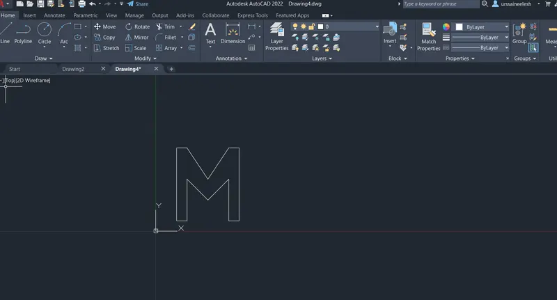
3. Steps for creating the geometry in p-4 using absolute coordinate system.
- Select the line tool by entering LINE command in the command tab.
- Specify the starting coordinate of point 1 as 2,1 in the command line.
- Specify the next coordinate of point 2 as 3,1 in the command line.
- Specify the next coordinate of point 3 as 3,5 in the command line.
- Specify the next coordinate of point 4 as 5,3 in the command line
- Specify the next coordinate of point 5 as 7,5 in the command line
- Specify the next coordinate of point 6 as 7,1 in the command line
- Specify the next coordinate of point 7 as 8,1 in the command line
- Specify the next coordinate of point 8 as 8,8 in the command line
- Specify the next coordinate of point 9 as 7,8 in the command line
- Specify the next coordinate of point 10 as 5,5 in the command line
- Specify the next coordinate of point 11 as 3,8 in the command line
- Specify the next coordinate of point 12 as 2,8 in the command line
- Click close on the command line.
RESULT:
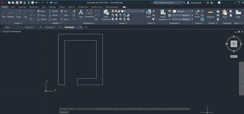
4. Steps for creating the geometry in P-5 using relative rectangular coordinate system.
- Select the LINE tool by entering LINE command in the command tab.
- Specify the staring coordinate of point 1 as 2,1 in the command line.
- Specify the next coordinate of point 2 as @1,0 in the command line.
- Specify the next coordinate of point 3 as @0,7 in the command line.
- Specify the next coordinate of point 4 as @5,0 in the command line.
- Specify the next coordinate of point 5 as @0,-6 in the command line.
- Specify the next coordinate of point 6 as @-3,0 in the command line.
- Specify the next coordinate of point 7 as @0,-1 in the command line.
- Specify the next coordinate of point 8 as @4,0 in the command line.
- Specify the next coordinate of point 9 as @0,8 in the command line.
- Specify the next coordinate of point 10 as @-7,0 in the command line
- click CLOSE on the command line.
RESULT:
5. Steps for creating the geometry in p-7 using Absolute coordinate system.
- Select the line tool by entering LINE command in the command tab.
- Specify the starting coordinate of point 1 as 2,1 in the command line.
- Specify the next coordinate of point 2 as 10,1 in the command line.
- Specify the next coordinate of point 3 as 10,7 in the command line
- Specify the next coordinate of point 4 as 2,7 in the command line.
- Click close on the command line.
- select the line tool by entering LINE command in the command tab.
- Specify the next coordinate of point 5 as 3,2 in the command line.
- Specify the next coordinate of point 6 as 5,2 in the command line
- Specify the next coordinate of point 7 as 5,5 in the command line
- Specify the next coordinate of point 8 as 3,5 in the command line
- click close on the command line.
- select the line tool by entering LINE command in the command tab.
- Specify the next coordinate of point 9 as 6,2 in the command line
- Specify the next coordinate of point 10 as 8,2 in the command line
- Specify the next coordinate of point 11 as 8,5 in the command line
- Specify the next coordinate of point 12 as 6,5 in the command line
- click close on the command line.
RESULT:
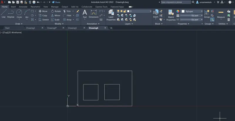
6. Steps for creating the geometry in p-8 using Relative rectangular coordinate system.
- Select the line tool by entering LINE command in the command tab.
- Specify the starting coordinate of point 1 as 0,0 in the command line.
- Specify the next coordinate of point 2 as @10,0 in the command line.
- Specify the next coordinate of point 3 as @0,2 in the command line
- Specify the next coordinate of point 4 as @-4,0 in the command line
- Specify the next coordinate of point 5 as @0,4 in the command line
- Specify the next coordinate of point 6 as @3,0 in the command line
- Specify the next coordinate of point 7 as @0,2 in the command line
- Specify the next coordinate of point 8 as @-8,0 in the command line
- Specify the next coordinate of point 9 as @0,-2 in the command line
- Specify the next coordinate of point 10 as @3,0 in the command line
- Specify the next coordinate of point 11 as @0,-4 in the command line
- Specify the next coordinate of point 12 as @-4,0 in the command line
- Click close on the command line.
RESULT:
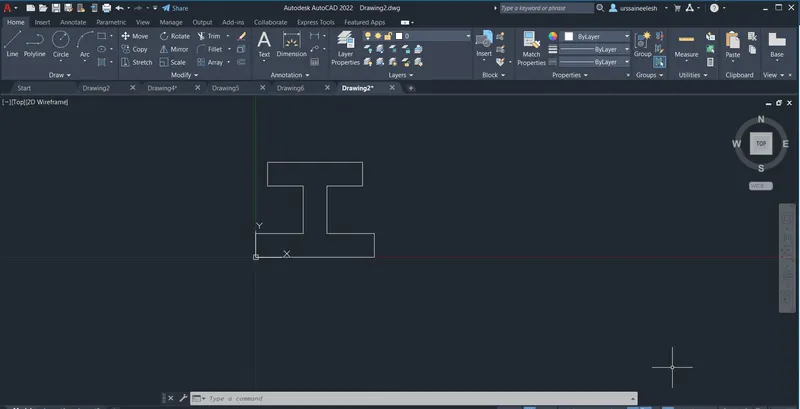
7. Drafting the geometry given in p-9
- Select the line tool by entering LINE command in the command tab.
- Specify the starting coordinate of point as 1,1 in the command line.
- Specify the next coordinate of point 2 as 6,1 in the command line.
- Specify the next coordinate of point 3 as 6,3 in the command line
- Specify the next coordinate of point 4 as 3,3 in the command line
- Specify the next coordinate of point 5 as 3,2 in the command line
- Specify the next coordinate of point 6 as 2,2 in the command line
- Specify the next coordinate of point 7 as 2,4 in the command line
- Specify the next coordinate of point 8 as 5,4 in the command line
- Specify the next coordinate of point 9 as 5,6 in the command line
- Specify the next coordinate of point 10 as 1,8 in the command line
- click close on the command line.
RESULT:
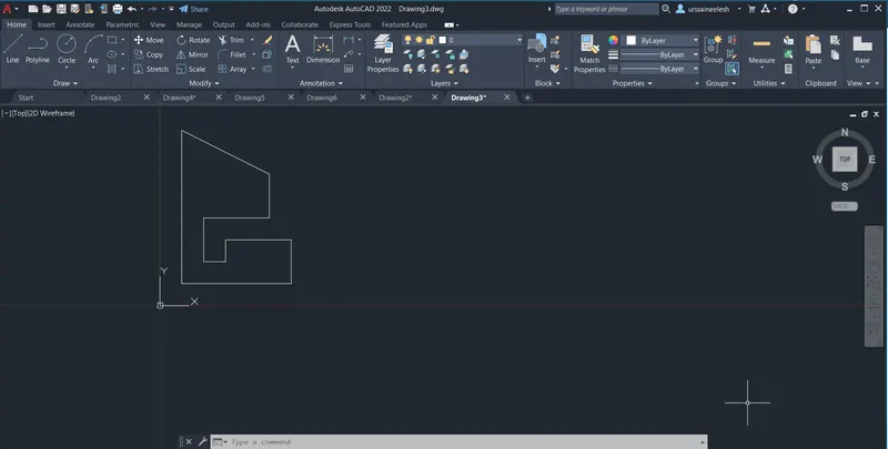
8. Steps for creating the geometry in p-10 using Relative polar coordinate system.
- Select the line tool by entering LINE command in the command tab.
- Specify the first coordinate of point 1 as 1,1 in the command line.
- Specify the next coordinate of point 2 as @2<0 in the command line.
- Specify the next coordinate of point 3 as @3<90 in the command line
- Specify the next coordinate of point 4 as @3<0 in the command line
- Specify the next coordinate of point 5 as @4<90 in the command line
- Specify the next coordinate of point 6 as @5<180 in the command line
- select the line tool by entering LINE command in the command tab.
- Specify the next coordinate of point 7 as 5,2 in the command line
- Specify the next coordinate of point 8 as @3<0 in the command line
- Specify the next coordinate of point 9 as @2<90 in the command line
- Specify the next coordinate of point 10 as @3<180 in the command line
- click close on the command line.
RESULT:
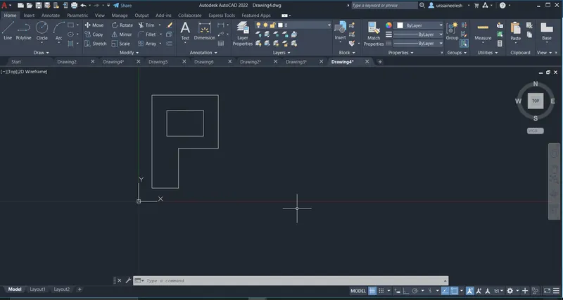
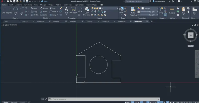
Steps for creating the wood profile using Direct distance entry method:
- Select the line tool by entering LINE command in the command tab.
- Specify the starting coordinate of point as 0,0 in the command line.
- Enter the length of point 2 as 10 in the command line towards +ve x- axis.
- Enter the length of point 3 as 1 in the command line towards +ve y- axis.
- Enter the length of point 4 as 2 in the command line towards -ve x- axis.
- Enter the length of point 5 as 4 in the command line towards +ve y- axis.
- Enter the length of point 6 as 2 in the command line towards +ve x- axis.
- Enter the length of point 7 as 5.831 in the command line at an angle of <149.036 from +ve x- direction while keeping polar tracking on.
- Enter the length of point 8 as 5.831 in the command line at an angle of < 210.964 from +ve x-direction while keeping polar tracking on.
- Enter the length of point 9 as 2 in the command line towards +ve x-axis.
- Enter the length of point 10 as 5 in the command line towards -ve y-axis.
- Enter the length of point 11 as 2 in the command line towards +ve x- axis.
- click close on the command line.
- select the circle tool by entering CIRCLE command in the command tab.
- Specify centre point of circle 5,4.
- Specify radius of circle as 2
RESULT:-
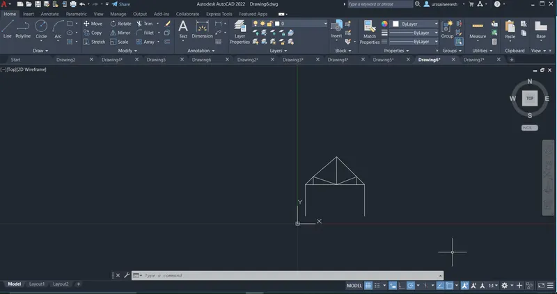
Steps for creating the queen post truss using abosolute coordinate. and direct distance method
- Select the line tool by entering LINE command in the command tab.
- specify the starting point 1 as 1,1 in the command line
- specify the next coordinate point 2 as 0,4 in the command line.
- specify the next coordinate point 3 as 1,0 in the command line
- specify the next coordinate point 4 as 0,1 in the command line
- specify the next coordinate point 5 as 2.536, -1.963 command line
- specify the next coordinate point 6 as 2.536, 3.563 in the command line
- specify next coordinate point 7 as 3.563,-3.563 in the command line.
- specify next coordinate point 8 as -3.563,0 in the command line.
- specify next coordinate point 9 as 3.499,1 in the command line.
- specify next coordinate point 10 as -3.499,-1 in the command line.
- press esc and use direct distance method from starting point as point 2 in perivous method from that to point 6 step up a mid point and press right click to from an inclined line.
- press esc on ur laptop.
RESULT:
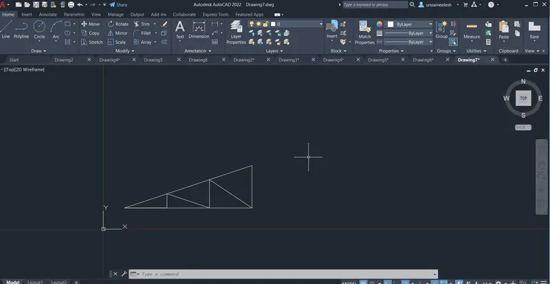
Steps for creating the mono pitch using absolute coordinate method.
- select the line tool by entering LINE command in the command tab.
- Specify the starting coordinate of point 1 as 1,1 in the command line.
- Specify the starting coordinate of point 2 as 7,1 in the command line.
- Specify the starting coordinate of point 3 as 7,3 in the command line.
- click close on the command line.
- Select the line tool by entering LINE command in the command tab.
- Specify the starting coordinate of point 4 as 3,1 in the command line.
- Specify the starting coordinate of point 5 as 3,1.667 in the command line.
- Specify the starting coordinate of point 6 as 5,1 in the command line.
- Specify the starting coordinate of point 7 as 5,2.333 in the command line.
- Specify the starting coordinate of point 8 as 7,1 in the command line.
- press esc to cancel the line command.
RESULT:
RESULT:
Hence the creation of gemometries by coordinate system is done by using Autocad software.