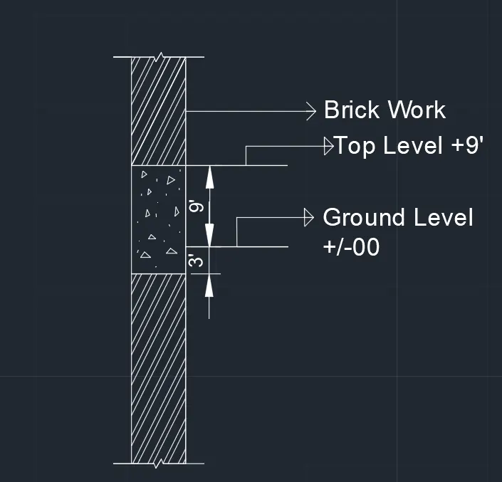
Creation of Column Schedule and Drawing Template using AutoCad
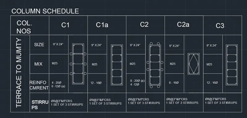
Aim - Create a column schedule as shown in the figure.
Introduction - Column schedule means the table containing all the details of column required during construction process.
Column schedule contains marking of column ,size of column and numbers of bars , diameter of bars used ,stirrups details and location of bars etc.Column schedule is given to us structural engineer.
Commands Used - Line , Circle , Dimensions ,Text, Fillet ,Trim and offset.
Procedure - Type units in command line then select length type as engineering and precision as 0'-0"and insertion scale as inches and press ok.
Select line command and draw a table with the help of line command. By using the line command and draw the panel on the ribbon, or by entering L and then pressing enter. Draw line segment by picking several random points. Terminate the command by pressing enter. Press the enter or spacebar to repeat the line command.
From home tab and innotation panel go on innotative text. Then manage text style and height for text 8".and then apply and set current.
Now select single line command and type required texts in the table format. Now Draw column reinforcement details for C1 and C1a columns. Using rectangle command ,fillet command etc.
Result -
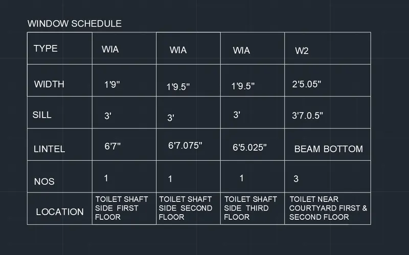
Aim - Create a window schedule as shown in the figures.
Introduction - Window schedule means the table containing the details of window.
Window schedule contains type ,width ,number ,height and location of window.
Sometimes it contains the type of material used for the construction.
Commands Used - Line , Circle ,Dimensions ,Text ,Fillet ,trim and offset.
Procedure - from the home tab and inotation panel go on innotative text. The manage text style and apply and set current.
Now draw table by using line comand.
now add all the text by using sinle line text command.
Result -
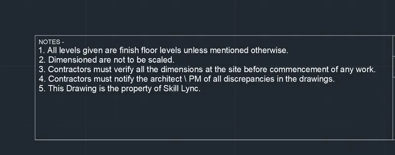
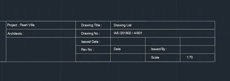
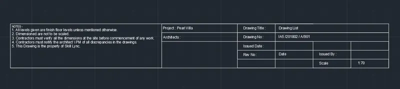
Aim - Create the drawing template as shown in the figure.
Introduction - A drawing template file is a drawing file that has been saved with a Dwt file extension and it specify the styles ,setting ,and layouts in drawing including title blocks.The default drawing template files are provided as samples.
Create all of the objects in the drawing that younwant as in template. Then click file menu save as and ,under file format, select Auro CAD drawing template. Then in the save drawing as a dialogue box, File name text box ,enter a name for the drawing template and click save.
Commands Used - Line , Circle ,dimensions,Text ,fillet ,trim ,Offset.
Procedure - Set limit by 150' x 100' by using Lmax command and by using line command to draw drawing page border.and draw to create drawing template.
Now add all the necessary data in to the table formed. By using single text command and height as 8'.
then go on save as then select drawing template. then enter file name and then click on save.
Result -
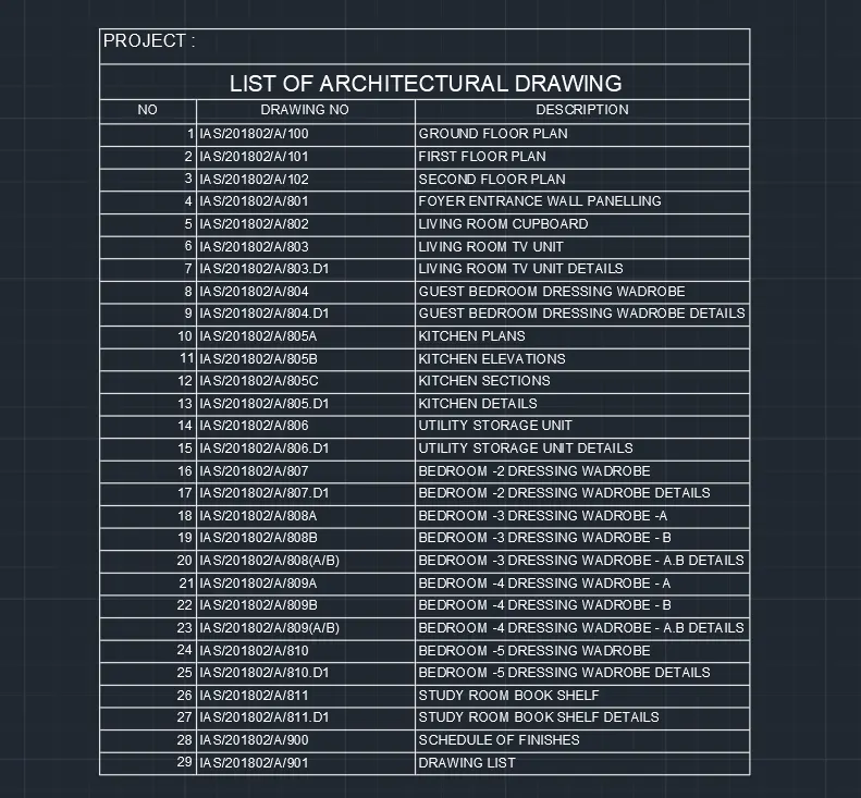
Aim - Create the list of drawing schedule as shown in the figure
Introduction - Schedule of drawing - it is the list drawing with detailed name ,numbers and all details of drawing.
Commands Used - Text ,line and table command
Procedure - Enter table command in command line. Then insert table dialogue box will pop up. Then enter columns as 3 and row as 30.1st Row title ,2nd row title and all other rows data. And then click on ok.
Now by using tabledit command enter text. For no column select alignment as middle center. For drawing no column select alignment as middle left. and for description column select alignment as middle left.
Result -
Aim - Create the Beam detail as shown in the figure and provide text wherever given
Introduction - Beam section - A long , thick piece of wood ,metal , concrete ,especially used to support weight in building or other structure.Beam takes load from above structural element.
Commands used - Line ,offset ,trim, Dimensions.
Procedure - First of all to set the limit by using Limax command. Then by using units command ,type units in command line ,type length as enginnering and precision as 0'-0". and insertion scale as inches and then press ok.
By using line commad draw wall and section of beam.
Now give the required dimensions to the figure by using dimensions command.
Result -