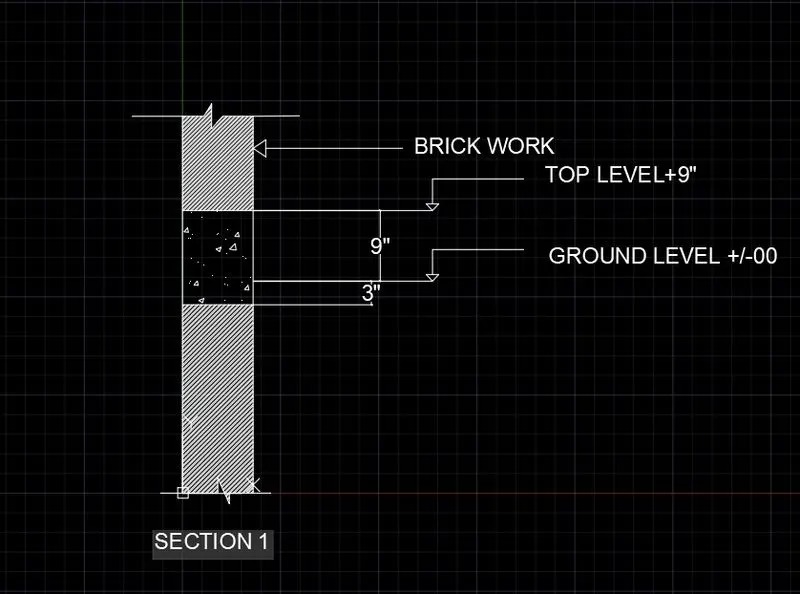
Creation of Column Schedule and Drawing Template using AutoCad
AIM:
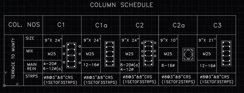
To create a column schedule as given in figure by using AutoCAD
Introduction:The column schedule is created by the help of line tool. Specification of the column schedule wrriten by the text command. The step-by-step procedure are as followed and result shown by the diagram
Procedure:
STEP 1)
Selection of Modal for Drawing Open AutoCAD
STARTUP enter for new drawing
Enter new value for startup 1 enter
Create new file (a dialog box open)
Go to last icon USE A WIZARD open
Select ADVANCE SETUP click OK
Select ENGINEERING, precision 0’-0”>NEXT>NEXT>NEXT> NEXT>FINISH
UN enter for unit setting
Select ENGINEERING, precision 0’-0” in type
Insertion scale select INCHES Click OK
LIM enter for set limit
Specify lower left corner 0,0 enter
Specify upper right corner 100’,100’ enter
Z enter for zoom
Zoom for select ALL or A enter
STEP 2)
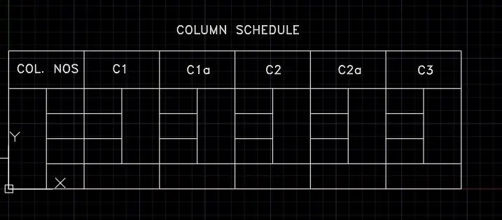
Table Creation for Column Schedule
Invoke the line command by entering L
Specify the first point 0,0 enter
Specify the next point @36’,0 enter
Specify the next point @0,11’ enter
Specify the next point @-36’,0 enter
Specify the next point C enter
O enter for OFFSET
Specify offset distance 2’ enter
Select object to offset click on bottom horizontal line
Specify point on side to offset move cursor upside
Continue the offset the line 3 time
O enter for OFFSET
Specify offset distance 3’ enter
Select object to offset click on left vertical line
Specify point on side to offset move cursor right-side
Continue the offset the line 11 time
TR double enter for trim
Select the unnecessary line to trim and created desired shape of table
STEP 3)
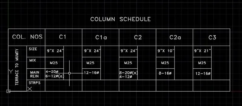
Name Specified on Table
ST enter for STYLE TEXT dialog box
Select the font name as romans.shx
and change the text height as 8”
Apply > Set Current > Close
DT enter for text
Specify rotation angle of text 0 enter
Specify the start point of the text click at the top of table
Type the name as COLUMN SCHEDULE (table heading)
Move cursor on first box of table
Left click in first row of table and type the name of box
Continue one by one type name for title box of the table and Esc
Change the text height as 5” from text style
DT enter for new text
Specify rotation angle of text 90 enter
Specify the start point of the text click at the first column of the table
Type the name as TERRACE TO MUMTY enter and Esc
Again, DT enter for new text
Specify rotation angle of text 0 enter
Specify the start point of the text click in the box
Type the name as SIZE
Move cursor & click another box to specify the name
Similarly specify all the boxes name Esc
STEP 4)
Section of Column Created in Table
REC enter for rectangle
Create random size of rectangle which is fitted in empty space of the table
Specify first corner point of rectangle left click
Specify other corner point move cursor upside & left click Esc
O enter for offset
Specify offset distance 1” enter
Select object to offset click on rectangle
Specify point on side to offset move cursor inside of the rectangle Esc
Create a circle in rectangle at corners (for presentation of vertical bar)
Trim the corner lines of the offseted rectangle (which is outside of circle)
Copy the circle as per required distance
Hatching the circle by solid
The section of column is created as previous for C1a, C2, C2a, C3
RESULT :
Q2
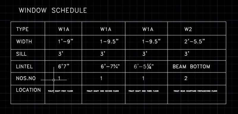
AIM: To create a window schedule as given in figure by using AutoCAD
Introduction:The step-by-step procedure are as followed and result shown by the diagram
Procedure:
STEP 1)
Selection of Modal for Drawing Open AutoCAD
STARTUP enter for new drawing
Enter new value for startup 1 enter
Create new file (a dialog box open)
Go to last icon USE A WIZARD open
Select ADVANCE SETUP click OK
Select ARCHITECTURAL, precision 0’-1/4”>NEXT>NEXT>NEXT> NEXT>FINISH
UN enter for unit setting
Select ARCHITECTURAL, precision 0’-1/4” in type
Insertion scale select INCHES Click OK
LIM enter for set limit
Specify lower left corner 0,0 enter
Specify upper right corner 100’,100’ enter
Z enter for zoom
Zoom for select ALL or A enter
STEP 2)
Table Creation for Window Schedule Home > Ribbon > Annotation > Table
Column 5
Data Row 4
First Row Cell Style DATA
Second Row Cell Style DATA
STEP 3)
Name Specified on Table ST enter for STYLE TEXT dialog box
Select the font name as ARIAL
and change the text height as 6”
Apply > Set Current > Close
Enter the Name of Boxes
Reduced the text height according to given figure from annotation ribbon
RESULT :
Q3
AIM: To create a drawing template as given in figure by using AutoCAD
Introduction:The step-by-step procedure are as followed and result shown by the diagram
Procedure:
STEP 1)
Selection of Modal for Drawing Open AutoCAD
STARTUP enter for new drawing
Enter new value for startup 1 enter
Create new file (a dialog box open)
Go to last icon USE A WIZARD open
Select ADVANCE SETUP click OK
Select ARCHITECTURAL, precision 0’-0”>NEXT>NEXT>NEXT> NEXT>FINISH
UN enter for unit setting
Select ARCHITECTURAL, precision 0’-0” in type
Insertion scale select INCHES Click OK
LIM enter for set limit
Specify lower left corner 0,0 enter
Specify upper right corner 100’,100’ enter
Z enter for zoom
Zoom for select ALL or A enter
STEP 2)
Table Created for Drawing Template REC enter for RECTANGLE
Specify first corner point 0,0
Specify other corner point @100’,12’-6” enter
O enter for offset
Specify offset distance 3” enter
Select object to offset click on rectangle
Specify point on side to offset move cursor in side & click
X enter for explode the rectangle
Select objects as internal rectangle enter
O enter for offset
Select object to offset 45’ enter
Specify point on side to offset move cursor right side & click
O enter for offset
Specify offset distance 3” enter
Specify point on side to offset move cursor right side & click
O enter for offset
Select object to offset 25’ enter
Specify point on side to offset move cursor right side & click
O enter for offset
Specify offset distance 3” enter
Specify point on side to offset move cursor right side & click
TR enter for TRIM the unnecessary line
O enter for offset
Specify offset distance 3’ enter
Select object to offset click on top horizontal offseted line
Specify point on side to offset move cursor down side & click
Again click 3’ offseted line & move cursor down side
Same as repeat offset twice for last box
O enter for offset at 2’ distance twice for down side
O enter for offset at 6’ distance from right side to left side three times
Further offset the offseted line at 4’ distance from right to left side
TR enter for trim the unnecessary line
STEP 3)
TEXT Created for Drawing Template ST enter for STYLE TEXT dialog box
Select the font name as romans.shx
and change the text height as 8”
Apply > Set Current > Close
MT(MTEXT) enter multiline text
Specify first corner left click on the top of the box
Specify opposite corner move cursor right side then left click
Type the notes enter Esc
Repeat the same as above for all boxes to type their names
RESULT :

Q4
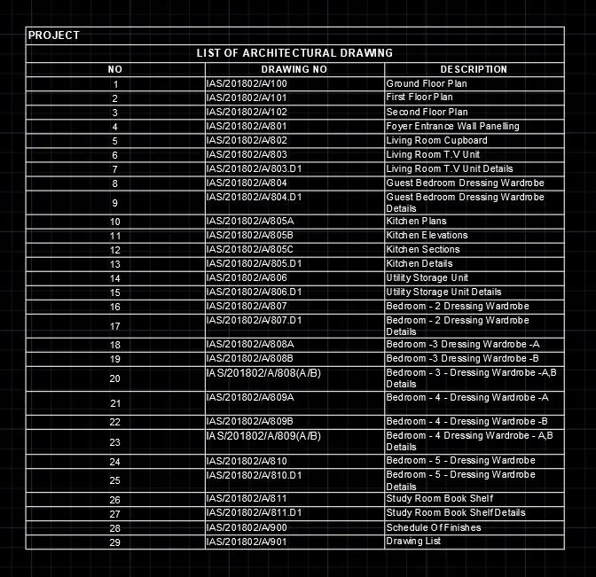
AIM: To create a list of drawing schedule as given in figure by using AutoCAD
Introduction:The step-by-step procedure are as followed and result shown by the diagram
Procedure:
STEP 1)
Selection of Modal for Drawing Open AutoCAD
STARTUP enter for new drawing
Enter new value for startup 1 enter
Create new file (a dialog box open)
Go to last icon USE A WIZARD open
Select ADVANCE SETUP click OK
Select ARCHITECTURAL, precision 0’-0”>NEXT>NEXT>NEXT> NEXT>FINISH
UN enter for unit setting
Select ARCHITECTURAL, precision 0’-0” in type
Insertion scale select INCHES Click OK
LIM enter for set limit
Specify lower left corner 0,0 enter
Specify upper right corner 100’,100’ enter
Z enter for zoom
Zoom for select ALL or A enter
STEP 2)
Table Creation for Window Schedule Home > Ribbon > Annotation > Table
Column 3, Data Row 30, Second Row Cell Style DATA (select from dialog)
STEP 3)
Name Specified on Table ST enter for STYLE TEXT dialog box
Select the font name as Calibri
and change the text height as 6”
Apply > Set Current > Close
Enter the Name of both title & first data row
Change the font style romans.shx & text size 6” for other data from text style
RESULT:
Q5
AIM: To Create the Beam detail as shown in the figure:
PROCEDURE:
STEP 1:
- In the command prompt type UNITS > Engineering> Inches
STEP 2:
- In the command prompt type Line ( to create the column )
- In the command prompt type Text to text the given drawings
- In the command prompt type HATCH to hatch the given drawings
RESULT: