Drafting of various geometries using Chamfer, Fillet tool in AutoCad
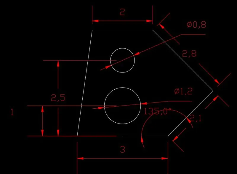
AIM : To draw the given drawing using AutoCAD software
PROCEDURE
STEP 1 :
• In the command prompt type Units and select decimal unit
STEP 2:
•In the command prompt type PL (Polyline)
In the command prompt specify start point 1,1
In the command prompt type @3<0
In the command prompt type @2.12 <45
In the command prompt type @2.83<135 In the command prompt type @ 2<180
In the command prompt click close
STEP 3: (TO DRAW CIRCLE)
In the command prompt type OBJECT SNAP In the object snap click on END POINT, Select the midpoint of line with dimension 3
MIDPOINT.In the command prompt type @1.90
Q• In the menu bar click circle > centre,diameter
With the help of the cursor click on the endpoint of the previous line which is taken as centre of the circle
In the command prompt type 1.20 (diameter)Delete 1< 90 line
STEP 4:
In the command prompt type OBJECT SNAP In the object snap click on END POINT, MIDPOINT.
Select the midpoint of line with dimension 3
In the command prompt type @2.50<90
In the menu bar click circle > centre,
diameter With the help of the cursor click on the endpoint of the previous line which is taken as centre of the circle
In the command prompt type 0.80( diameter)
Q Delete @2.50<90 line
RESULT
AIM -To draw the given drawing using AutoCAD software
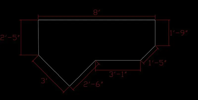
PROCEDURE
STEP 1:
In the command prompt type Units >type> Architectural > precesion > 0'-0" STEP 2:
• select polar tracking > 45,90,135,80 In the command prompt type line
Select a point with the help of cursor keeping the cursor to the left with the angle of 45 type distance 3'keeping the cursor to the right with the angle of 45 type distance 2'-6"
keeping the cursor to t right wth the angle of 0 type distance 3'-1" keeping the cursor to t right wth the angle of 135 type distance 1-5"
keeping the cursor to t right wth the angle of 90 type distance 1'-5"
keeping the cursor to t right wth the angle of 180 type distance 8'
keeping the cursor to t right wth the angle of 270 type distance 2'-5"
RESULT:
AIM :To draw the given drawing using AutoCAD software
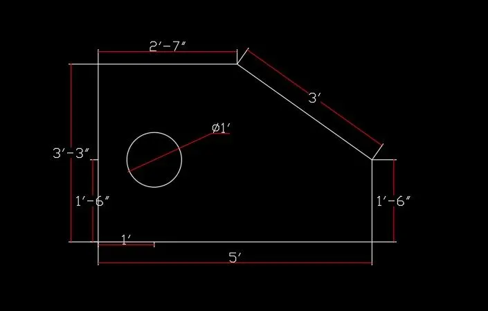
PROCEDURE:
STEP 1:In the command prompt type Units >type> Engineering precesion 0'-0"
STEP 2:In the command prompt type line • In the command prompt type distance 5' 0.10"
• In the command prompt type distance 3'-3.00" • In the command prompt type distance 2'-6.50"> enter
• In the command prompt type line • In the command prompt type distance 1'-6"
• Join the gap using line command at an angle of 125
STEP 3
In the command prompt type line
In the command prompt type offset • In the command prompt specify the offset distance as 1'0.60" (select 5' 0.10" line and offset.
• In the command prompt type offset • In the command prompt specify the offset distance as 1' 0.3" (select 3'-3.0" line and offset .
• With the help of the cursor click on the intersection point of the two lines, therefore it is the centre of the circle needed.
• In the menu bar click on circle > centre, diameter centre is the intersection point, diameter 1-0 is type in the comman prompt
RESULT:
AIM :To draw the given drawing using AutoCAD software
PROCEDURE:
STEP 1:
In the command prompt type Units >type> Engineering precesion 0'-0"
STEP 2:
In the command prompt type line
• In the command prompt type distance 5' 0.10"
• In the command prompt type distance 3'-3.00"
• In the command prompt type distance 2'-6.50"> enter
• In the command prompt type line
• In the command prompt type distance 1'-6"
• Join the gap using line command at an angle of 125
STEP 3
In the command prompt type line
In the command prompt type offset
• In the command prompt specify the offset distance as 1'0.60" (select 5' 0.10" line and offset
• In the command prompt type offset •
In the command prompt specify the offset distance as 1' 0.3" (select 3'-3.0" line and offset it
• With the help of the cursor click on the intersection point of the two lines, therefore it is the centre of the circle needed.
• In the menu bar click on circle > centre, diameter
centre is the intersection point, diameter 1-0 is type in the comman prompt
RESULT:.
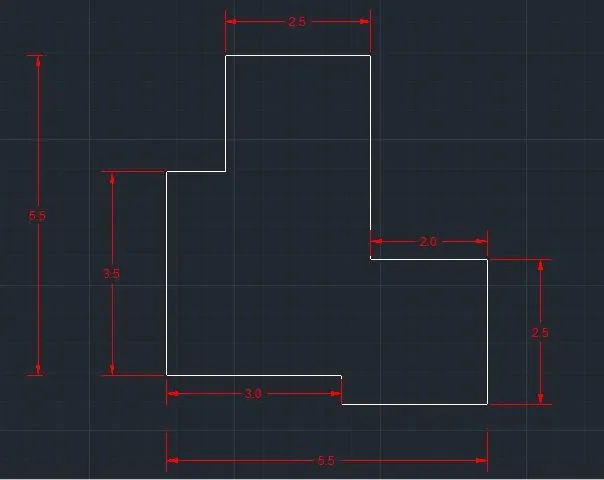
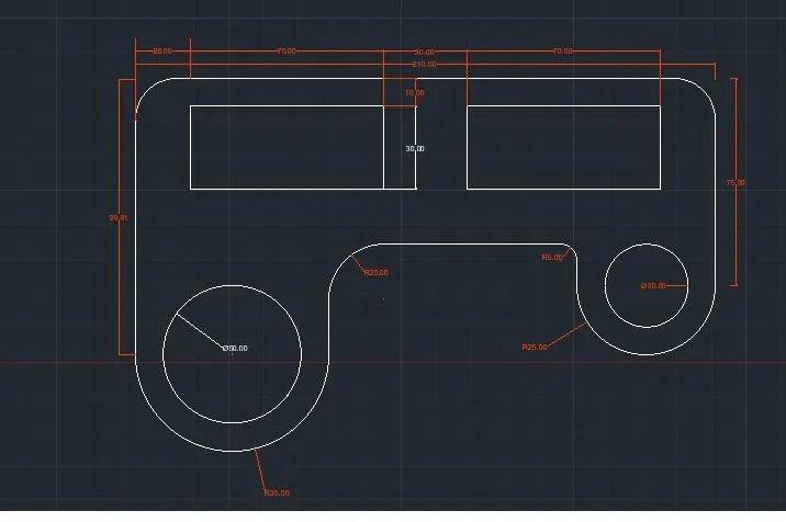
AIM:To draw the given drawing using AutoCAD software
PROCEDURE:
STEP 1:
In the command prompt type Units >type> decimal precesion 0.0
STEP 2:
In the command prompt type line • In the comman prompt type distance 100
• In the command prompt type distance 210
• In the command prompt type distance 75 In the command prompt type fillet
• In the command prompt type radius 15.0 , select the 100 line and 210 line ,select the 210 line and 75 line
STEP 3:
• From the end point of 100 draw a horizontal line of 70
• In the menu bar click circle > centre, radius ,center is the midpoint of the previous line and
radius is 35 • In the menu bar click circle centre, diameter > centre is the centre of the previous circle (R35)
and diameter is 50
• From the end point of line 70 draw a vertical line of 40.
STEP 4:
• From the end point of 75 draw a horizontal line of 50
• In the menu bar click circle > centre, radius center is the midpoint of the previous line ai radius is 25
In the menu bar click circle centre, diameter
centre is the centre of the previous circle (R25) and diameter is 30
From the end point of line 50 draw a vertical line of 15. Close the gap with the help of the line.
STEP 5:
• In the command prompt type fillet > radius > 20
select the two lines to get the curve
• In the command prompt type fillet > radius > 6
select the two lines to get the curve
STEP 6:
• At a distance of 20 from the left top corner and 10 from the top (specify starting point)
• From that point with the help of the rectangular command draw a rectangle with dimensions 70and 30
offset the rectangle at a distance of 30 with the help of offset command
RESULT:
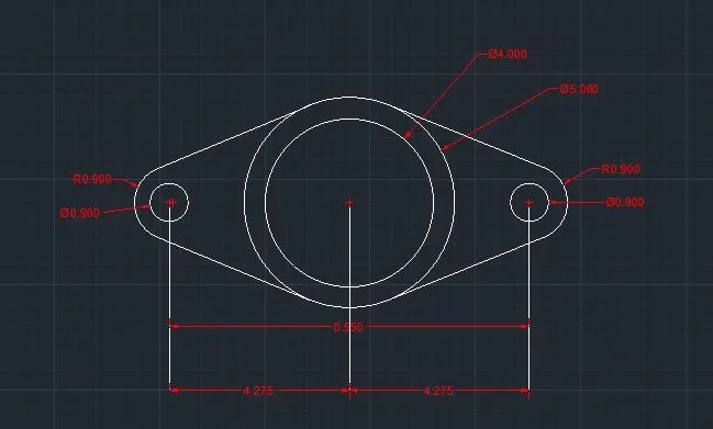
AIM:To draw the given drawing using AutoCAD software
PROCEDURE:
STEP 1:
In the command prompt type Units >type> decimal > precesion > 0.000
STEP 2: (left side)
• In the command prompt type line distance>8.550
• In the menu bar > circle > centre, diameter
• centre is the end point of line 8.550 and diameter is 0.90
• In the menu bar > circle > centre, radius
• centre is the end point of line 8.550 and radius is 0.90
STEP 3:(right side)
• In the menu bar > circle > centre, diameter
• centre is the end point of line 8.550 and diameter is 0.90
• In the menu bar > circle > centre, radius m,centre is the end point of line 8.550 and radius is 0.90
STEP 4:
• In the menu bar > circle > centre, diameter, centre is the midpoint of line 8.550 and diameter is 50
• In the menu bar > circle > centre, radius centre is the midpoint of line 8.550 and diameter is 40
STEP 5:
• Join the tangets of the outer circle with helpof lines and trim the extras .
RESULT :
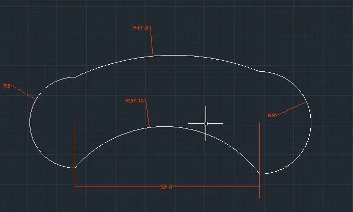
AIM:To draw the given drawing using AutoCAD software
PROCEDURE:
STEP 1:
In the command prompt type Units >type>engineering precesion > 0.0
STEP 2: (left side)
• In the command prompt type line > distance>32'-6"
• In the menu bar > circle > centre, diameter
• centre is the end point of line 32-6" and diameter is 8'
STEP 3:(right side)
• In the menu bar > circle > centre, diameter, centre is the end point of line 32'-6" and diameter is 9'
STEP 4: (DOWN ARC)
• In the menu bar circle centre, diameter
• centre is the end point of line 32-6" and diameter is 32'-6" (LS)
• In the menu bar > circle > centre, diameter, centre is the end point of line 32'-6" and diameter is 32'-6" (RS)
• Point where two circles are intersecting (bottom) raw a circle with radius 32'-6"
• Thus arc is formed now trimmed the extras
STEP 5: (UP ARC)
• In the menu bar > circle > centre, diameter
• centre is the end point of line 32-6" and diameter is 33"-8" (LS)
• In the menu bar > circle > centre, diameter centre is the end point of line 32-6" and diameter is 32'-8" (RS)
• Point where two circles are intersecting(bottom) raw a circle with radius 41'-8"
• Thus arc is formed now trimmed the extras
RESULT:
AIM:
To draw the given drawing using AutoCAD software
PROCEDURRE:
STEP 1:
• In the command prompt type Units >type> decimal precesion > 0.0 STEP 2:
•In the command prompt type rec› dimensions> 5 >5 offset the recangle and rotate it to the diamond shape
using offset command offset rectangle and diamond
STEP 2:
Using trim command trim out the unwanted lines as shown in the drawing
RESULT:
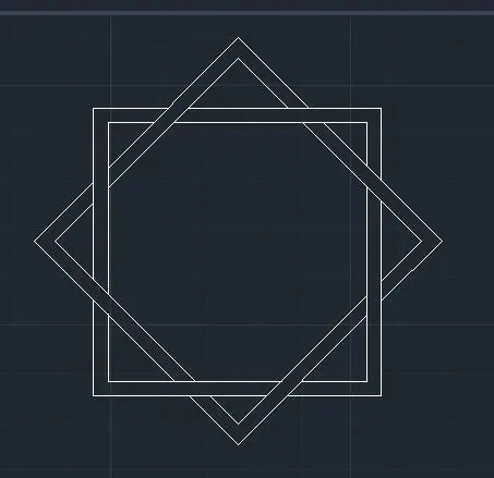
AIM: To draw the given drawing using AutoCAD softwar
PROCEDURE:
STEP 1:
In the command prompt type Units >type> engineering precesion 0.0
STEP 2:
In the command prompt type line > distance> 20' 4"> 9'> 3'>4' 6" 4' 6"> 1'2" >5' 4"> 1'2"> 4'6"> close
STEP 3:(LS V)
• Take offset distance of 3' from corner and 2' 8" from top with offset command With the line command draw a V and polar coordinates must be 45.90,135,180
STEP 4: (RSV)
• Take offset distance of 3' from corner and 3' 7" from top with offset command
• With the line command draw a V and polarcoordinates must be 30,60,90,120
STEP 5 (CENTRE DIAMOND)
• Take offset distance of 10'2" from corner and 6' 10' from top with offset command
• Keeping the intersection point as centre draw a diamond with radius 3 and angle 90
RESULT:
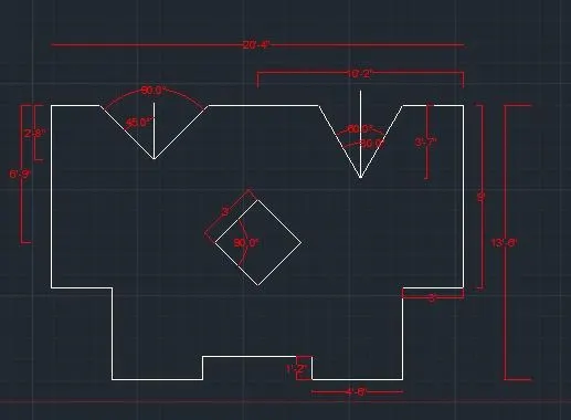
AIM:
To draw the given drawing using AutoCAD software
PROCEDURE:
STEP 1:
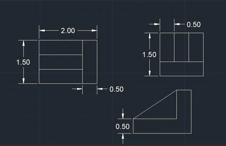
In the command prompt type Units >type> decimal precesion > 0.0 STEP 2: (RECTANGLE AT THE RIGHT)
In the command prompt type line
• In the command prompt type distance 1.5
• In the command prompt type distance 1.5
• In the command prompt type distance 1.5
• In the command prompt type distance 1.5
• In the command prompt type offset
• In the command prompt type offset distance 0.5
• With the help of offset get a horizontal line of distance 0.5
• With the help of offset get two vertical line of each distance 0.5
STEP 2: (RECTANGLE AT THE TOP)
In the command prompt type line
• In the command prompt type distance 2.0
• In the command prompt type distance 1.5 • In the command prompt type distance 2.0
• In the command prompt type distance 1.5 In the command prompt type offset
• In the command prompt type offset distance 0.5
• With the help of offset get a vertical line of distance 0.5
• With the help of offset get two horizontal line each distance 0.5
STEP 3: (DRAWINGT AT THE CENTRE)
Extended the horizontal lines from the right
• Extended the vertical lines from the top rectangular drawing
• With the help of line command join the intersecton points
• And trim the extras with the help of trim command
RESULT:
AIM:
To draw the given drawing using AutoCAD software
PROCEDURE:
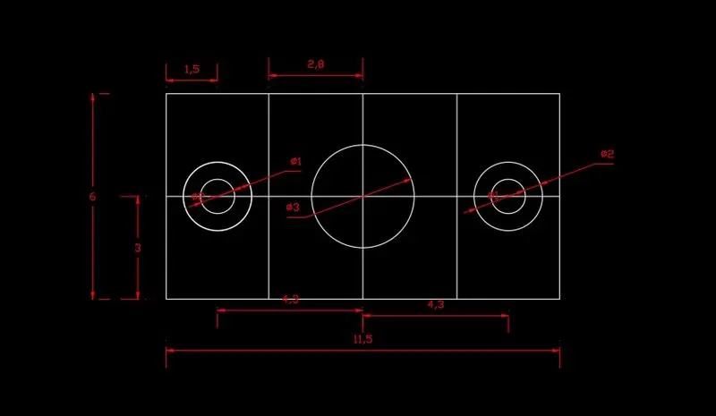
STEP 1:
In the command prompt type Units >type> decimal precesion > 0.0
STEP 2:
In the command prompt type line • In the command prompt type distance 11.5
• In the command prompt type distance 6.0
• In the command prompt type distance 11.5
• In the command prompt click close
STEP 3: (left side circle)
• Take a offset of 1.5 distance (from 6 line)
• Again take a offset of 1.5 from the previous line
• Take a offset of 3.0 distance (from 11.5 line)
• The intersection point of the two lines as the centre of the circle • In the menu bar click on circle > centre,diameter
• centre is the intersection point, type dimension as 2.0
• In the menu bar click on the circle > centre,
diameter , center is the intersection point, type dimension as 1.0 delete the line which is at the offset distance of 1.5
STEP 4:
(centre circle) take a offset distance of 2.8 from the previc/ line of the offset distance 3.0 Again take a offset distance of 2.8 from the previous line
• The intersection point at the starting offset distance is the centre point of the circle
• In the menu bar click on the circle > centre, diameter
• centre is the intersection point, type diameter as 3.0 delete the the first offset line which is at the distance 2.8 form the previous line of the offset distance 3
STEP 5: (right side circle)
• Take a offset of 1.5 distance (from 6 line) the intersection point of the two lines as the centre of the circle
• In the menu bar click on circle > centre,diameter
• centre is the intersection point, type dimension as 2.0
• In the menu bar click on the circle > centre,diameter center is the intersection point, type dimension as 1.0
delete the line which is at the offset distance of 1.5 delete the offset line of distance 3 from 11.5 distance line
RESULT: