Creation of Column Schedule and Drawing Template using AutoCad
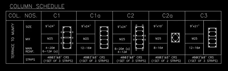
1. AIM : To Create a column schedule as shown in the figure.
COMMAND USED :
- Limits
- Zoom
- Xline
- Line
- Circle (C) command
- DO (Donet) Command
- X (Explode) Command
- Dimlinear
- DT command
- ED command
- MT Command
- Unit command
- LW command
- Extend command
- Trim command
STEP WISE PROCEDURE :
Step - 1
- Start with line command (L)
- Unit and Grid set 1" and 1"
- Enter the xline command : 1,1
- Draw the line in both X and Y axis
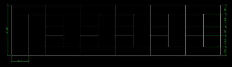
- Run command offset (O) and create Table with asumed size as shown in fig.
- Offset (O) in X direction 1'-7" multiple 12 times
- Offset (O) command in Y direction 9.5", 1'0.4", 10", 1'-2.6" and 10"
- Trimmed all extra line as as fig. with command (TRIM)
Step - 2
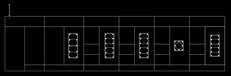
1st : Column size 9" x 24", 10 Reinforcement bar and 1 set of 3 strips used:
- Enter the xline command : 1,1
- Make a rectangle box for column size 9" x 24" with Command (REC)
- Specify point and make the rectangle @9,24
- Run command offset (O) and create 0.5" in inner side for column cover approx 20mm (0.5")
- Make a circle with (C) command with tangent corner of rectange box X and Y direction
- (MI) command for mirror of circle in X direction
- Explode command (X) for inner rectangel box
- Divide command for reinforcement rod shown (5 nos. in one side)
- Copy both circle and paste in divided 5 point (including 1st copied circle point)
- Donut (DO) command used for Circle filled for shown Reinforcement rod
- Join the circle with line as per shown strips
- Fillet the all corner as per drawing
- Trimmed the all extra line as per fig. required
2nd : Column size 9" x 24", 12 Reinforcement bar and 1 set of 3 strips used:
- Enter the xline command : 1,1
- Make a rectangle box for column size 9" x 24" with Command (REC)
- Specify point and make the rectangle @9,24
- Run command offset (O) and create 0.5" in inner side for column cover approx 20mm (0.5")
- Make a circle with (C) command with tangent corner of rectange box X and Y direction
- (MI) command for mirror of circle in X direction
- Explode command (X) for inner rectangel box
- Divide command for reinforcement rod shown (6 nos. in one side)
- Copy both circle and paste in divided 6 point (including 1st copied circle point)
- Donut (DO) command used for Circle filled for shown Reinforcement rod
- Join the circle with line as per shown strips
- Fillet the all corner as per drawing
- Trimmed the all extra line as per fig. required
3rd : Column size 9" x 24", 12 Reinforcement bar and 1 set of 3 strips used:
- Enter the xline command : 1,1
- Make a rectangle box for column size 9" x 24" with Command (REC)
- Specify point and make the rectangle @9,24
- Run command offset (O) and create 0.5" in inner side for column cover approx 20mm (0.5")
- Make a circle with (C) command with tangent corner of rectange box X and Y direction
- (MI) command for mirror of circle in X direction
- Explode command (X) for inner rectangel box
- Divide command for reinforcement rod shown (6 nos. in one side)
- Copy both circle and paste in divided 6 point (including 1st copied circle point)
- Donut (DO) command used for Circle filled for shown Reinforcement rod
- Join the circle with line as per shown strips
- Fillet the all corner as per drawing
- Trimmed the all extra line as per fig. required
4th : Column size 9" x 10", 8 Reinforcement bar and 1 set of 2 strips used:
- Enter the xline command : 1,1
- Make a rectangle box for column size 9" x 10" with Command (REC)
- Specify point and make the rectangle @9,10
- Run command offset (O) and create 0.5" in inner side for column cover approx 20mm (0.5")
- Make a circle with (C) command with tangent corner of rectange box X and Y direction
- (MI) command for mirror of circle in X direction
- Explode command (X) for inner rectangel box
- Divide command for reinforcement rod shown (3 nos. in one side)
- Copy both circle and paste in divided 3 point (including 1st copied circle point) in Y direction
- Copy both circle and paste in divided 2 point (including 1st copied circle point) in X direction
- Donut (DO) command used for Circle filled for shown Reinforcement rod
- Join the circle with line as per shown strips
- Fillet the all corner as per drawing
- Trimmed the all extra line as per fig. required
5th : Column size 9" x 21", 12 Reinforcement bar and 1 set of 3 strips used:
- Enter the xline command : 1,1
- Make a rectangle box for column size 9" x 24" with Command (REC)
- Specify point and make the rectangle @9,24
- Run command offset (O) and create 0.5" in inner side for column cover approx 20mm (0.5")
- Make a circle with (C) command with tangent corner of rectange box X and Y direction
- (MI) command for mirror of circle in X direction
- Explode command (X) for inner rectangel box
- Divide command for reinforcement rod shown (6 nos. in one side)
- Copy both circle and paste in divided 6 point (including 1st copied circle point)
- Donut (DO) command used for Circle filled for shown Reinforcement rod
- Join the circle with line as per shown strips
- Fillet the all corner as per drawing
- Trimmed the all extra line as per fig. required
Step - 3
- Enter the DT Command
- Font used romans
- Enter asumed size of text height 4"
- Enter Text direction '0'
- Type 'COLUMN SCHEDULE' and make under line
- Copy the existing text (Column Schedule) and leave under abd
- Type Col. Nos.
- Copy existing text for C1, C1a, C2, C2a and C3 (Left aligned)
- Enter the DT Command
- Font used romans
- Enter asumed size of text height 2"
- Enter Text direction '0'
- Type 'SIZE'
- Copy for Mix, Main Reinf., Strips and all sizes of (column size (as 9"x24", Mix (as M25), Main Reinf. (as 4-20Ø, 6-12Ø(a) and strips details (as Ø8@3"&8" 1set of 3 strips) centre aligned
- Enter the DT Command
- Font used romans
- Enter asumed size of text height (2.5")
- Enter Text direction '90'
- Type 'TERRACE TO MUMTY'
FINAL RESULT :
2. AIM : To Create a window schedule as shown in the figures:
COMMAND USED :
- Limits
- Zoom
- Xline
- Line
- X (Explode) Command
- Dimlinear
- DT command
- ED command
- MT Command
- Unit command
- Extend command
- Trim command
STEP WISE PROCEDURE :
Step - 1
- Start with line command (L)
- Unit and Grid set 1" and 1"
- Enter the xline command : 1,1
- Draw the line in both X and Y axis
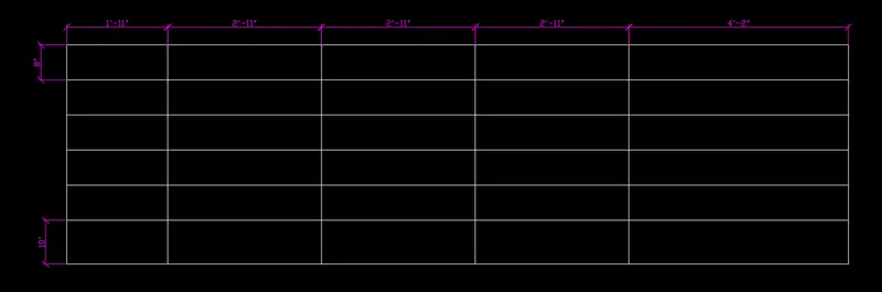
- Run command offset (O) and create a table with asumed size as shown in fig.
- Offset (O) in X direction 1'-11", 2'-11", 2'-11", 2'-11" and 4'-2"
- Offset (O) command in Y direction 10", 8" (5 times)
- Trimmed all extra line as as fig. with command (TRIM)
Step - 2
- Enter the DT Command
- Font used romans
- Enter asumed size of text height 4"
- Enter Text direction '0'
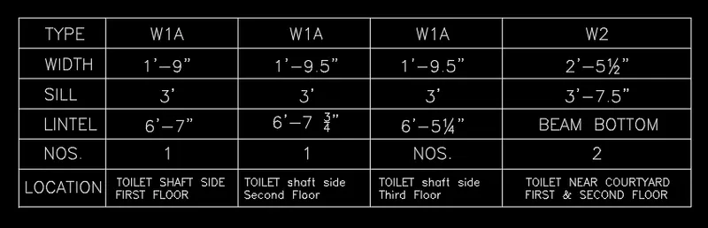
- Type the text 'TYPE'
- Copy existing text for WIDTH, SILL, LINTEL and LOCATION (Left aligned)
- Enter the DT Command
- Font used romans
- Enter asumed size of text height 4"
- Enter Text direction '0'
- Type 'W1A'
- Copy for W1A, W2 and all WIDTH (as 1'-9"), SILL (as 3'), LINTEL (as 6'-7"), NOS. (as 1) & LOCATION (as Toilet shaft side first floor)centre or left aligned as required
FINAL RESULT :
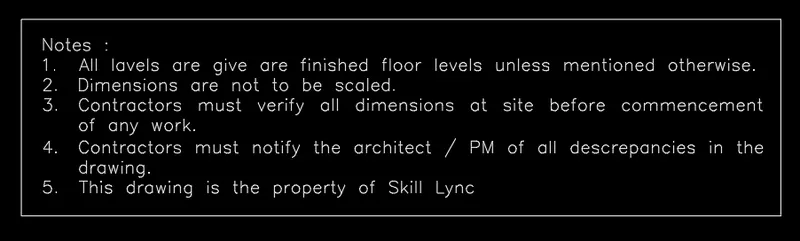
3. AIM : To Create the drawing template as shown in the figure:< Use the Notes as in the figure>
COMMAND USED :
- Limits
- Zoom
- REC command for rectangle box
- MT Command
- Unit command
- Offset (O) command
- Extend
- Trim command
STEP WISE PROCEDURE :
Step -1
- Start with line command (L)
- Unit and Grid set 1" and 1"
- Enter the REC command : 1,1
- Draw the rectangle box as asumed size @4',16'
- Enter the MT Command for text
- Font used 'romans'
- Enter asumed size of text height 4" (
- Enter Text direction '0'
- Type the text Notes : Enter
- Tipeed with number list (Justify aligned)
RESULT (Step-1) :
Step -2
- Start with line command (L)
- Unit and Grid set 1" and 1"
- Extend the rectangle box 36' in X direction
- Offset the box in outer side with asumed size 1"
- Draw the line, Extend and trim as required as per shown in fig.
- Enter the MT Command for text
- Font used 'romans'
- Enter asumed size of text height 4" (
- Enter Text direction '0'
- Copy the existing text and paste for (Project, Architect, Drawing title, Drawing no., issued date, rev. no., Drawing list, issued by, scale. etc.) and type as per shown in fig.
FINAL RESULT :

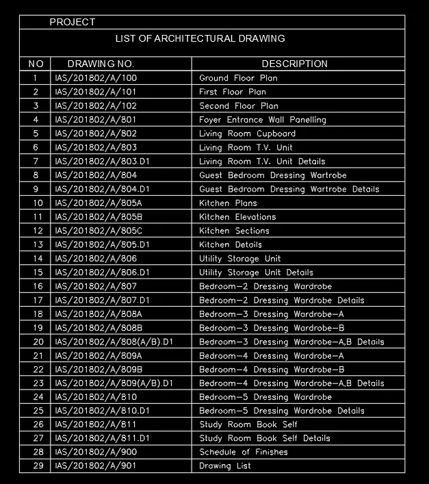
4. AIM : To Create the list of drawing schedule as shown in the figure:
COMMAND USED :
- Limits
- Zoom
- Line
- MT Command
- Unit command
- Offset (O) command
- Extend
- Trim command
STEP WISE PROCEDURE :
Step -1
- Start with line command (L)
- Unit and Grid set 1" and 1"
- Enter the xline command : 1,1
- Draw the line in both X and Y axis
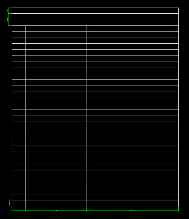
- Run command offset (O) and create a table with asumed size as shown in fig.
- Offset (O) in X direction 1'-10.4", 8'-5.8" and 12'-9.9"
- Offset (O) command in Y direction 10" and Array 29
- Offset (O) command in Y direction 1"-8" and 10"
- Trimmed all extra line as as fig. with command (TRIM)
RESULT (Step-1) :
Step - 2
- Enter the DT Command
- Font used 'Arial'
- Enter asumed size of text height 4"
- Enter Text direction '0'
- Type the text 'PROJECT'
- Copy existing text for LIST OF ARCHITECTURAL DRAWING, NO, DRAWING NO. and DESCRIPTION (WITH Left aligned)
- Enter the DT Command
- Font used 'romans'
- Enter asumed size of text height 4"
- Enter Text direction '0'
- Type '1'
- Press Tab in keyboard and Type IAS/201802/A/100
- Press Tab in keyboard and Type Ground Floor plan
- Repeat 29 times for all sr. no.29 rows
FINAL RESULT :
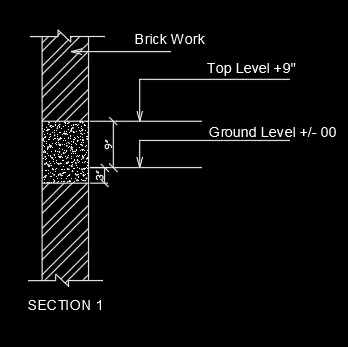
5. AIM : To Create the Beam detail as shown in the figure and provide text wherever given.
COMMAND USED :
- Limits
- Zoom
- Line
- DT Command
- Unit command
- Offset (O) command
- Extend
- Trim command
STEP WISE PROCEDURE :
Step -1
- Start with line command (L)
- Unit and Grid set 1" and 1"
- Enter the Line command : 1,1
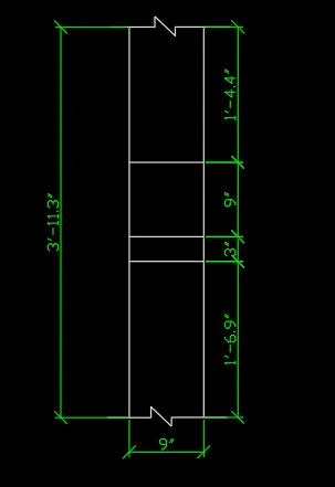
- Draw the asumed line size 3'-11.3" in Y axis
- Run command offset (O) in X direction 9" as shown in fig.
- Enter the Line command : 1,1
- Draw a line in X direction 9"
- Offset (O) in Y direction 1'-6.9", 3", 9" and 1'-4.4"
RESULT (Step-1) :
Step -2
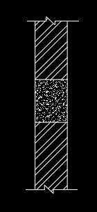
- Start Hatch command (H)
- Fill as per dra wing
Step - 3
- Enter the DT Command
- Font used 'Arial'
- Enter asumed size of text height 4"
- Enter Text direction '0'
- Type the text 'Brick Work'
- Copy existing text for type 'Top Level +9" and Ground Level +/-00'
FINAL RESULT :