Creating a Floor plan, Footing detail and Isometric view using AutoCad
C-1 :
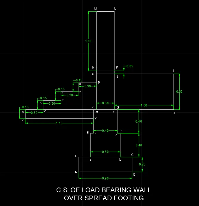
AIM : To create C.S. of load bearing wall over spread footing.
Step - 1
- Start with line command (L)
- Line specify 1st point : 2,1 (Point A)
- Specify 2nd point : X direction (East) 0.90 (Point B)
- Specify 3rd point : Y direction (North) 0.25 (Point C)
- Specify 4th point : -X direction (West) 0.90 (Point D)
- Specify 5th point : -Y direction (South) 0.25 / Close (Point A)
- Offset with CD line in Y direction (0.40) for draw point line EF
- Offset with EF line in Y direction (0.40) for draw point line ZG
- Offset with ZG line in Y direction (0.60) for draw point line OJ
- Offset with OJ line in Y direction (0.05) for draw point line NK
- Offset with NK line in Y direction (1.00) for draw point line ML
- Create a vertical construction (Xline) command (XL) from the centre point of (0.90) length (AB) for the offset command run in X and -X direction.
- Offset with verticle construction line in X direction 0.25 and - X direction 0.25 and maked point ab, EF and trimmed extra line as per drawing.
- Create a vertical construction (Xline) command (XL) from the centre point of (0.50) length (EF) for the offset command run in X and -X direction.
- Offset with verticle construction line in X direction 0.20 and - X direction 0.20 and maked point cd, ZG and trimmed extra line as per drawing.
- Create a vertical construction (Xline) command (XL) from the centre point of (0.40) length (ZG) for the offset command run in X and -X direction.
- Offset with verticle construction line in X direction 0.15 and - X direction 0.15 and maked point ef, OJ, NK, ML and trimmed extra line as per drawing.
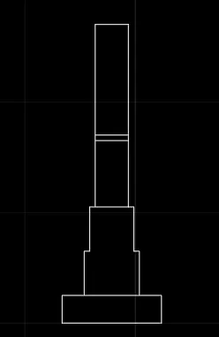
Result for Step-1
Step - 2
- Extend line in -X direction with point Z length 1.15 and mention point W
- Offset with ZW line in -Y direction 0.15
- Offset with ZW line in Y direction 0.15
- Repeat offset 3 times in Y direction
- Offset with Me line in -X direction 0.30
- Repeat offset 4 times in -X direction and make point P, Q, R, S, T, U, V, W, X and Y, and trimmed all extra line as per drawing.
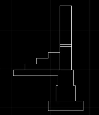
Result for Step-2 with Step-1
Step - 3
- Extend line in X direction with point f (asume 1.00- not mentioned in drawing) length 1.00 and mention point H
- Copy fH line and paste in y direction 0.60 and make point JI
- Join the line I and H
Final Result :
C-2 :
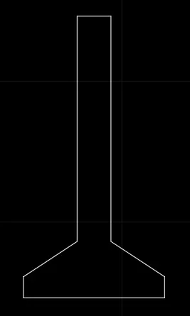
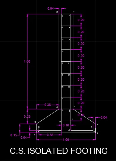
AIM : To create C.S. Isolated footing.
Step - 1
- Start with line command (L)
- Line specify 1st point : 2,1 (Point A)
- Specify 2nd point : X direction (East) 1.00 (Point B)
- Offset with AB line in Y direction (0.15) for draw point line HC
- Offset with HC line in Y direction (0.25) for draw point line GD
- Create a vertical construction (Xline) command (XL) of centre point of (1.00) length (AB) for the offset command run in X and -X direction.
- Offset with verticle construction line in X direction 0.50 and - X direction 0.50
- Offset with verticle construction line in X direction 0.12 and - X direction 0.12 and maked point C, D, E, F, G & H, and trimmed extra line as per drawing.
- Join the line with point G H and D C.
Result for Step-1
Step - 2
- Offset AB line in Y direction 0.04
- Offset AH line in X direction 0.04
- Offset BC line in -X direction 0.04 and make the point b & e
- Create a line with point b in Y direction 0.04 and mention point 'a' (asumed size) not mentioned in drawing
- Create a line with point e in Y direction 0.04 and mention point 'f' (asumed size) not mentioned in drawing
- Create a vertical construction (Xline) command (XL) of centre point of (1.00) length (AB) for the offset command run in X and -X direction.
- Offset with verticle construction line in X direction 0.08 and - X direction 0.08 and trimmed all extra line as per drawing.
- Offset EF line in -Y direction 0.20 repeat 9 times in -Y direction and make the point c, d, g, h, i, j, k, l, m, n, o, p, q, r, s, t, u, v, w, x, y, z and trimmed all extra line as per drawing.
Final Result :
C-3 :
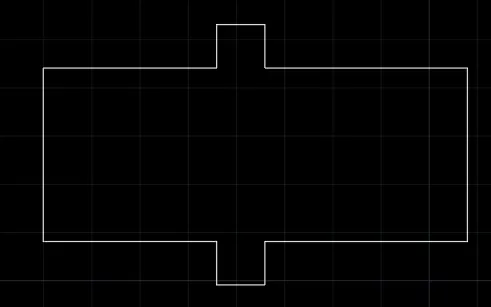
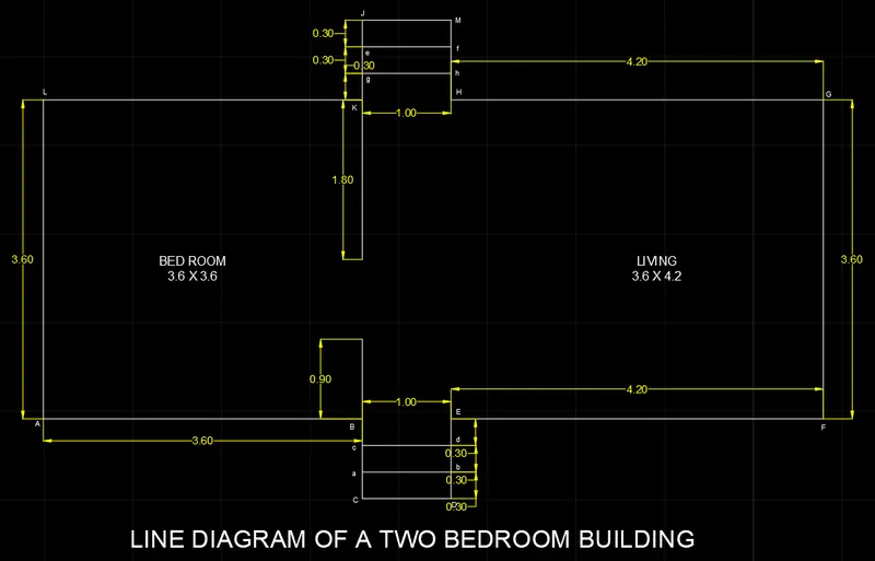
AIM : To create a line diagram of a two bedroom building.
Step - 1
- Start with line command (L)
- Line specify 1st point : 2,1 (Point A)
- Specify 2nd point : X direction (East) 3.60 (Point B)
- Specify 3rd point : -Y direction (South) 0.90 (Point C)
- Specify 4th point : X direction (East) 1.00 (Point D)
- Specify 5th point : Y direction (North) 0.90 (Point E)
- Specify 6th point : X direction (East) 4.20 (Point F)
- Specify 7th point : Y direction (North) 3.60 (Point G)
- Specify 8th point : -X direction (West) 4.20 (Point H)
- Specify 9th point : Y direction (North) 0.90 (Point I)
- Specify 10th point : -X direction (West) 1.00 (Point J)
- Specify 11th point : -Y direction (South) 3.60 (Point K)
- Specify 12th point : -X direction (West) 3.60 (Point L)
- Specify 13th point : -Y direction / Close
Result for Step-1
Step - 2
- Offset CD line in Y direction 0.30 repeat 2 times in Y direction and make point a, b, c & d
- Offset JI line in -Y direction 0.30 repeat 2 times in Y direction and make point e, f, g & h
- Extend line from B point to Y direction 0.90 and make point N
- Extend line from K point to -Y direction 1.80 and make point M
Final Result :
C-4 :
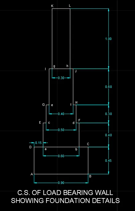
AIM : To create C.S. of load bearing wall showing foundation details.
Step - 1
- Start with line command (L)
- Line specify 1st point : 2,1 (Point A)
- Specify 2nd point : X direction (East) 0.90 (Point B)
- Specify 3rd point : Y direction (North) 0.45 (Point C)
- Specify 4th point : -X direction (West) 0.90 (Point D)
- Specify 5th point : -Y direction (South) 0.45 / Close
- Offset with CD line in Y direction (0.40) for draw point line EF
- Offset with EF line in Y direction (0.30) for draw point line GH
- Offset with GH line in Y direction (0.60) for draw point line IJ
- Offset with IJ line in Y direction (1.00) for draw point line KL
- Create a vertical construction (Xline) command (XL) from the centre point of (0.90) length (CD) for the offset command run in X and -X direction.
- Offset with verticle construction line in X direction 0.30 and - X direction 0.30 and maked point ab, CD and trimmed extra line as per drawing.
- Create a vertical construction (Xline) command (XL) from the centre point of (0.60) length (EF) for the offset command run in X and -X direction.
- Offset with verticle construction line in X direction 0.25 and - X direction 0.25 and maked point cd, EF and trimmed extra line as per drawing.
- Create a vertical construction (Xline) command (XL) from the centre point of (0.50) length (GH) for the offset command run in X and -X direction.
- Offset with verticle construction line in X direction 0.20 and - X direction 0.20 and maked point ef, GH and trimmed extra line as per drawing.
- Create a vertical construction (Xline) command (XL) from the centre point of (0.40) length (IJ) for the offset command run in X and -X direction.
- Offset with verticle construction line in X direction 0.15 and - X direction 0.15 and maked point gh, IJ & KL and trimmed extra line as per drawing.
Final Result :
C-5 :
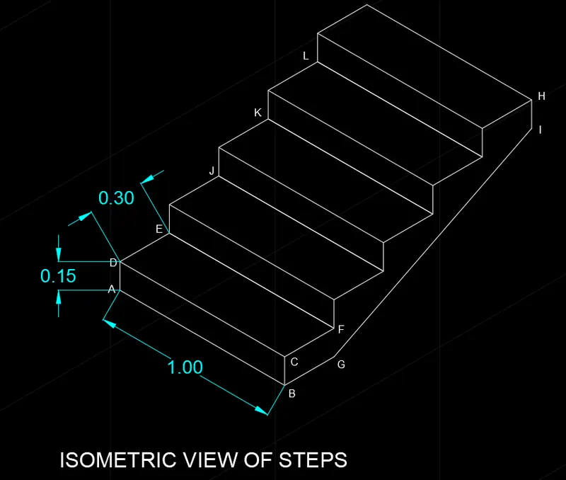
AIM : To create a Isometric view of steps.
- Start with line command (L)
- Line specify 1st point : 2,1 (in Left Isometric view) (Point A)
- Specify 2nd point : X direction (in Left Isometric view) 1.00 (Point B)
- Specify 3rd point : Y direction (in Left Isometric view) 0.15 (Point C)
- Specify 4th point : -X direction (in Left Isometric view) 1.00 (Point D)
- Close in -Y direction with (A)
- Next start from point D and specify 5 point : Y direction (in Top Isometric view) 0.30 (Point E)
- Specify 6th point : X direction (in Top Isometric view) 1.00 (Point F)
- Close in -Y direction with (C)
- Copy all with point A and paste 4 times with point E, J, K & L
- Extend line with point H to -Y direction 0.15 and make point I
- Extend line with point B to X direction 0.30 and make point G
- Join with line G and I.
Final Result :
C-6 :
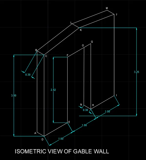
AIM : To create a Isometric view of Gable Wall.
Step - 1
- Start with line command (L)
- Line specify 1st point : 2,1 (in Left Isometric view) (Point A)
- Specify 2nd point : Y direction (in Left Isometric view) 3.00 (Point B)
- Specify 3rd point : X direction (in Left Isometric view) 0.30 (Point C)
- Specify 4th point : -Y direction (in Left Isometric view) 3.00 (Point D)
- Close with Point A
- Next start with point D (in Left Isometric view) X direction 1.00 (Point E)
- Specify next point in Y direction (in Left Isometric view) 2.42 (Point F)
- Specify next point in X direction (in Left Isometric view) 1.00 (Point G)
- Specify next point in -Y direction (in Left Isometric view) 2.42 (Point H)
- Specify next point in X direction (in Left Isometric view) 1.00 (Point I)
- Specify next point in Y direction (in Left Isometric view) 3.00 (Point J)
Result for Step-1
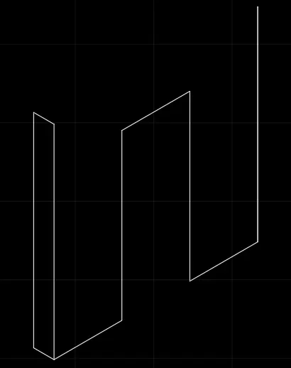
Step - 2
- Next start with point H (in Left Isometric view) -X direction 0.30 (Point N)
- Specify next point in Y direction (in Left Isometric view) 2.42 (Point O)
- Next maked point K(centre point of EH to Y direction 3.25 height) K
- Copy CB line and paste to point K and point J and maked point KL and JM
- Next join the line with B & L, C & K, K & J and L & M
Final Result :