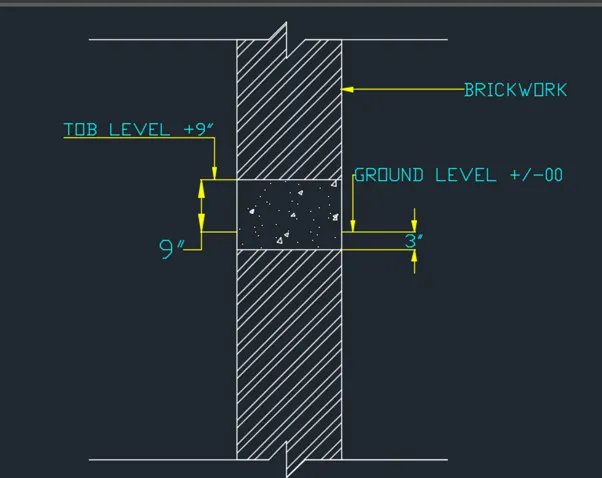
Creation of Column Schedule and Drawing Template using AutoCad
| Creation of Column Schedule and Drawing Template using AutoCad |
- Column Schedule
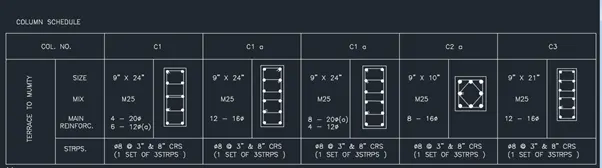
- Aim : To Create a Column Schedule as shown in below fig by using AutoCAD Software
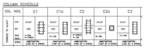
- Procedure :-
Step : 1 – To Draw the Table
- Click on AutoCAD application and open this application
- Type QNEW in command bar and enter
- Select default setting as Imperial ( feet and inches )
- Press Enter
- I have kept snap and grid setting off
- Keep ortho on
- Press UN and enter and set unit
- Type – Engineering
- Precision – 0’0”
- Enter
- Take line command
- Specify first point anywhere
- Specify next point as = @90’>0
- Specify next point as = @20’>90
- Specify next point = @90’>180
- Close it

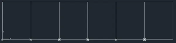
- Take divide command from command bar
- Select the object by selecting the horizontal line
- Enter the no of segment as 6
- Now change the point style to locate the dividation part
- Take object snap as ON
- Take line command
- Specify first point as > select a point on horizontal line
- Specify next point > on the opposite horizontal line, where object snap showing the perpendicular symbol.
- Take copy command
- Copy it at other points as shown below
- Again take point style command
- Select point style as regular
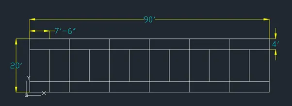
- Use offset command
- Specify offset distance > 4’
- Select the object > click on upper horizontal line and lower horizontal line
- Use offset command
- Specify distance as 7.5’
- Specify next point > until the end of table
- Trim the unwanted part
Step : 2 – To create and fill the Text in table
- Click on Annotation tab > Single line
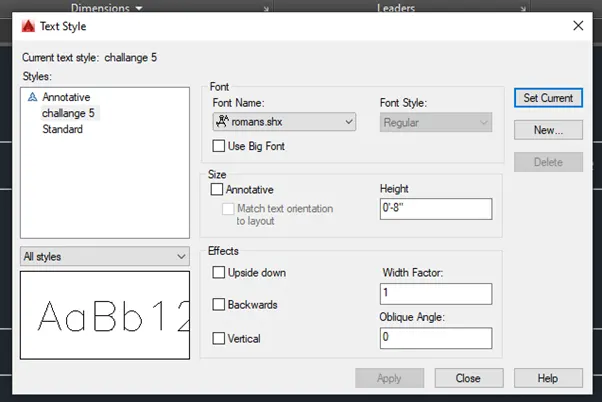
- Manage textile > New
- Style name as > Challenge 5 > OK
- Font Name > romans.shx.
- Height > 8”
- And press set current
- Write down all the necessary texts shown in schedule
- Keep rotation angle 0 for all the text
- Justify > left
- Take text edit command
- Select object > Click on TERRACE TO MUMTY
- Make rotation as 90
- Enter
Step : 3 – To Draw Column
- C1
- Take rectangle command
- Specify first point > anywhere
- Dimensions > 9” X 24”
- Take offset of rectangle at inner side by 1”
- Explode the last object
- Take divide command
- Divide in four segment
- Select the object as inner vertical line
- Use the line command to show the dividation
- Take a circle command
- Specify first point anywhere out of rectangle
- Specify radius as 0.5”
- Take hatch command
- Take a solid
- Specify object by clicking on the circle
- Copy that circle wherever it is necessary to show the bars
- Use filet command and select radius as 0.5”
- Select the object by clicking the sides of the inner sides of rectangle just like shown below
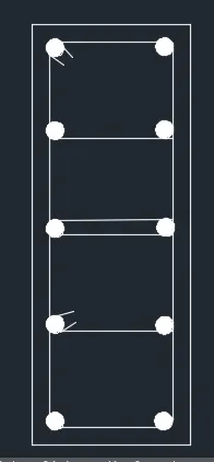
- C1 a :
- Take rectangle command
- Specify first point > anywhere
- Dimensions > 9” X 24”
- Take offset of rectangle at inner side by 1”
- Explode the last object
- Take divide command
- Select the object as inner vertical line
- Divide in five segment
- Use the line command to show the dividation
- Take a circle command
- Specify first point anywhere out of rectangle
- Specify radius as 0.5”
- Take hatch command
- Take a solid
- Specify object by clicking on the circle
- Copy that circle wherever it is necessary to show the bars
- Use filet command and select radius as 0.5”
- Select the object by clicking the sides of the inner sides of rectangle just like shown below
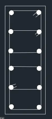
- C2 :
- Take rectangle command
- Specify first point > anywhere
- Dimensions > 9” X 24”
- Take offset of rectangle at inner side by 1”
- Explode the last object
- Take divide command
- Select the object as inner vertical line
- Divide in five segment
- Use the line command to show the dividation
- Take a circle command
- Specify first point anywhere out of rectangle
- Specify radius as 0.5”
- Take hatch command
- Take a solid
- Specify object by clicking on the circle
- Copy that circle wherever it is necessary to show the bars
- Use filet command and select radius as 0.5”
- Select the object by clicking the sides of the inner sides of rectangle just like shown below
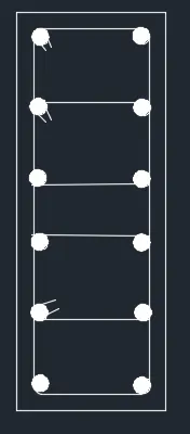
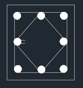
- C2 a :
- Take rectangle command
- Specify first point > anywhere
- Dimensions > 9” X 10”
- Take offset of rectangle at inner side by 1”
- Take line command
- Specify first point > click on midpoint of the inner rectangle
- Join all the midpoint of the rectangle by line command
- Take filet command
- Click > Multiple > radius as 0.5
- Click on all the sides
- Take a circle command
- Specify first point anywhere out of rectangle
- Specify radius as 0.5”
- Take hatch command
- Take a solid
- Specify object by clicking on the circle
- Copy that circle wherever it is necessary to show the bars as shown below
- C3 :
- Take rectangle command
- Specify first point > anywhere
- Dimensions > 9” X 21”
- Take offset of rectangle at inner side by 1”
- Explode the last object
- Take divide command
- Select the object as inner vertical line
- Divide in five segment
- Use the line command to show the dividation
- Take a circle command
- Specify first point anywhere out of rectangle
- Specify radius as 0.5”
- Take hatch command
- Take a solid
- Specify object by clicking on the circle
- Copy that circle wherever it is necessary to show the bars
- Use filet command and select radius as 0.5”
- Select the object by clicking the sides of the inner sides of rectangle just like shown below
- Move all these diagram and place it in a proper way as shown below
- Take the scale command
- Select the object
- Specify base point as centre of object
- Move the curser to get the increase size
- Enter
- Result :-
- WINDOW SCHEDULE
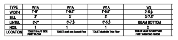
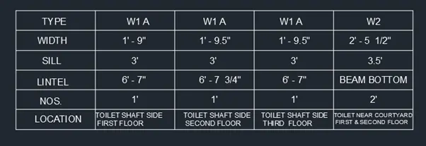
- Aim : To create Window Schedule as shown below by using AutoCAD Software
- Procedure :
Step : 1 – To Draw the Table
- Click on AutoCAD application and open this application
- Type QNEW in command bar and enter
- Select default setting as Imperial ( feet and inches )
- Press Enter
- I have kept snap and grid setting off
- Keep ortho on
- Press UN and enter and set unit
- Type – Engineering
- Precision – 0’0”
- Enter
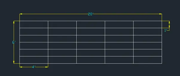
- Take line command
- Specify first point anywhere
- Specify next point as = @20’>0
- Specify next point as = @6’>90
- Specify next point = @20’>180
- Close it
Step : 2 – To create and fill the Text in table
- Click on Annotation tab > Single line
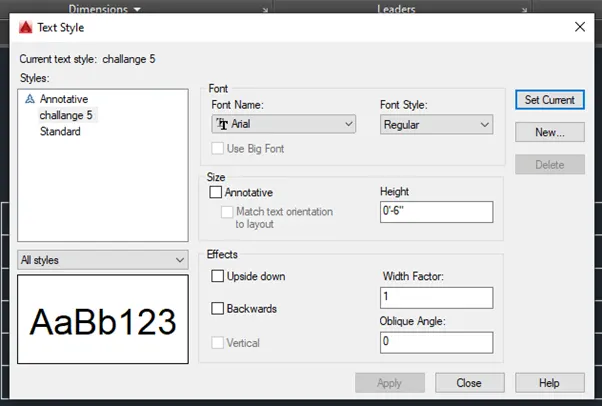
- Manage textile > New
- Style name as > Challenge 5 > OK
- Font Name > Arial
- Height > 4”
- And press set current
- Take single line text
- Specify start point in 1st box
- Set rotation angle 0
- Enter > write TYPE in 1st box
- Follow the same procedure for all other texts
- Write down all the necessary texts shown in schedule
- Result :-
- Drawing Template :
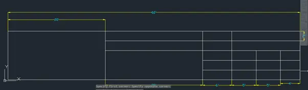
- Aim : To create Drawing Template as shown below by using AutoCAD Software.

- Procedure :
Step : 1 – To Draw the Table
- Click on AutoCAD application and open this application
- Type QNEW in command bar and enter
- Select default setting as Imperial ( feet and inches )
- Press Enter
- I have kept snap and grid setting off
- Keep ortho on
- Press UN and enter and set unit
- Type – Engineering
- Precision – 0’0”
- Enter
- Take line command
- Specify first point anywhere
- Specify next point as = @60’>0
- Specify next point as = @10’>90
- Specify next point = @60’>180
- Close it
- Take offset command
- Specify distance > 20’
- Select object as both the vertical lines
- Take offset command
- Specify distance > 2’
- Select object as horizontal line and take 4 offsets as shown below
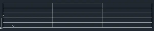
- Again take offsets of third vertical line such as shown below
- Trim the unwanted lines
Step : 2 – To create and fill the Text in table
- Click on Annotation tab > Single line
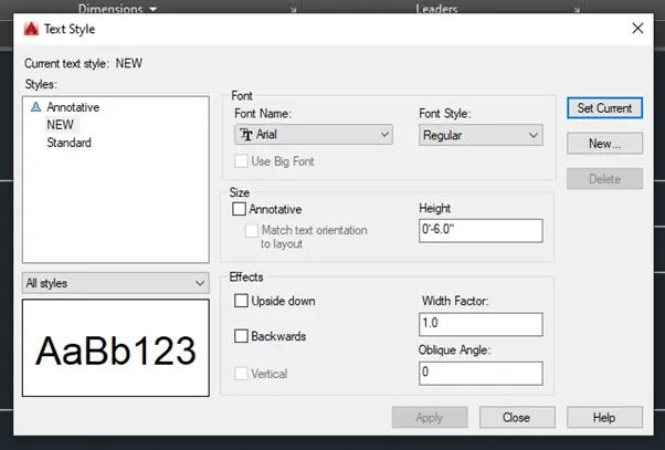
- Manage textile > New
- Style name as > NEW > OK
- Font Name > Arial
- Height > 6”
- And press set current
- Take single line text
- Specify start point in 1st box
- Set rotation angle 0
- Enter > write TYPE in 1st box
- Follow the same procedure for all other texts
- Write down all the necessary texts shown in schedule
- Result :-

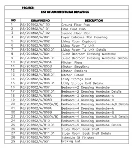
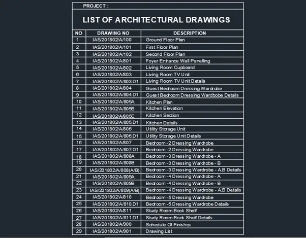
- List of Drawing Schedule
- Aim :- To create the list of drawing schedule as per shown below using AutoCAD software.
- Procedure :
Step : 1 – To Draw the Table
- Click on AutoCAD application and open this application
- Type QNEW in command bar and enter
- Select default setting as Imperial ( feet and inches )
- Press Enter
- I have kept snap and grid setting off
- Keep ortho on
- Press UN and enter and set unit
- Type – Engineering
- Precision – 0’0”
- Enter
- Take line command
- Specify first point anywhere
- Specify next point as = @25’>0
- Specify next point as = @34’>90
- Specify next point = @25’>180
- Close it
- Take offset command
- Offset the vertical line at a distances one at 2’ and another at 10’
- Take offset command
- Specify distance > 1’
- Select object as horizontal line and take 33 offsets as shown below
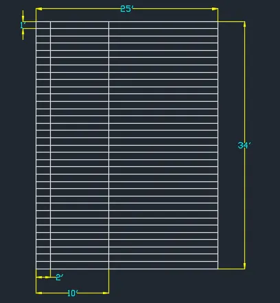
- Trim the above unwanted lines as shown below
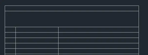
Step : 2 – To create and fill the Title Text in table
- Click on Annotation tab > Single line
- Manage textile > New
- Style name as > Title> OK
- Font Style > Bold
- Font Name > Arial
- Height > 10”
- And press set current
- Take single line text
- Specify start point in Title box
- Set rotation angle 0
- Enter > write List of Architectural Drawings in Title box
Step : 3 – To create and fill the Sub-Title Text in table
- Click on Annotation tab > Single line
- Manage textile > New
- Style name as > Sub-Title> OK
- Font Style > Bold
- Font Name > Arial
- Height > 6”
- And press set current
- Take single line text
- Specify start point in Title box
- Set rotation angle 0
- Enter > write Project in the required box
- Some more sub-titles add by using above steps
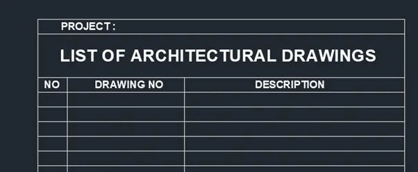
Step : 3 – To create the other Text in table
- Click on Annotation tab > Single line
- Manage textile > New
- Style name as > NEW> OK
- Font Style > Regular
- Font Name > Arial
- Height > 6”
- And press set current
- Take single line text
- Specify start point in 1st box
- Set rotation angle 0
- Enter > write 1 in the required box
- By using same procedure fill all the boxes as per above pic
- Result :-
- Beam Details
- Aim :- To create Beam Details as shown in below fig by using AutoCAD Software
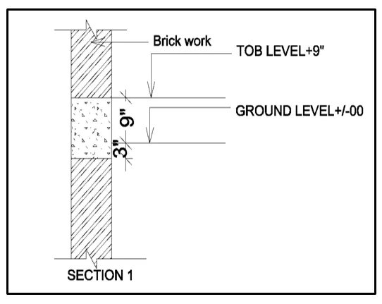
- Procedure :
Step : 1 – To Draw the C/S
- Click on AutoCAD application and open this application
- Type QNEW in command bar and enter
- Select default setting as Imperial ( feet and inches )
- Press Enter
- I have kept snap and grid setting off
- Keep ortho on
- Press UN and enter and set unit
- Type – Engineering
- Precision – 0’0”
- Enter
- Take line command
- Specify first point anywhere
- Specify next point as = @1’6”>0
- Specify next point as = @6’>90
- Specify next point = @1’6”>180
- Close it
- Take offset command
- Specify distance > 3’
- Select object as bottom horizontal line
- Take offset command
- Specify distance > 2’
- Select object as top horizontal line
- Draw the Cross-Section as shown below using line command
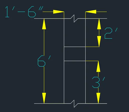
Step : 2 – To Hatch the C/S
- Take hatch command from draw panel
- Select pattern for brickwork as ANSI32
- Pick internal point
- Click inside the diagram, where we have to show brickwork
- Select that brickwork part > Open properties
- Pattern > Scale > 8
- Enter
- Take hatch command from draw panel
- Select pattern for beam as AR-CONCRETE
- Pick internal point
- Click inside the diagram, where we have to show concrete
- Enter
Step : 3 – To Create Text
- Take offset command
- And offset horizontal line at 3” distance

- Take dimensions command
- Provide the dimensions as per the diagram
- Click on Annotation
- Select leader command to direct the point and to text
- Select properties
- Arrow and text height as 3”
- General and leader colour as Cyan and Yellow
- Enter
- Result :-