Creation of Column Schedule and Drawing Template using AutoCad
Aim: To create a column schedule using various tools in autocad
Introduction: Creation of column schedule using autocad tools such as line tools and inserting the text using the Dtext command or single line text
Procedure:
Step1
Go to start menu and open the autocad 2014 software
Go to startmenu command and give value 1 and go to application menu and open a new file and create new drawig dialogue box opens
In this dialogue box set the units to feet inches and precision 0'-0.00" and press ok
Go to units command and set the units to engineering and precision is 0'-0.00" and insertion scale as inches
And go to limits command and specify lower left corner as 100' and upper right corner as 100'
Go to line command and draw a line of length 9" in horizontal direction and 24" in vertical direction
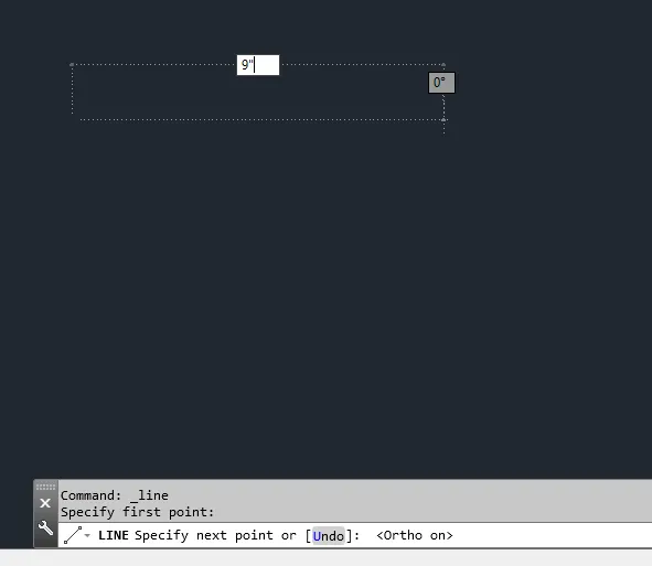
And a line height of 24" columns height using line tool
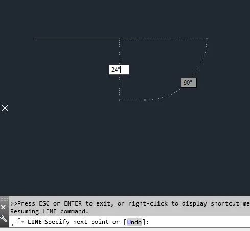
Give a cover of 0.5" inside using the line command
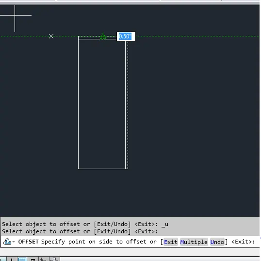
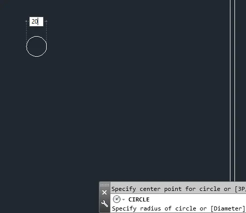
To create a bars of dia 20 go to units and set the units to decimal type and insertion scale as millimeters and press ok, then go to circle diameter option and draw a circle of dia 20mm
Take a offset of 5" inside the columns by using offset command tool
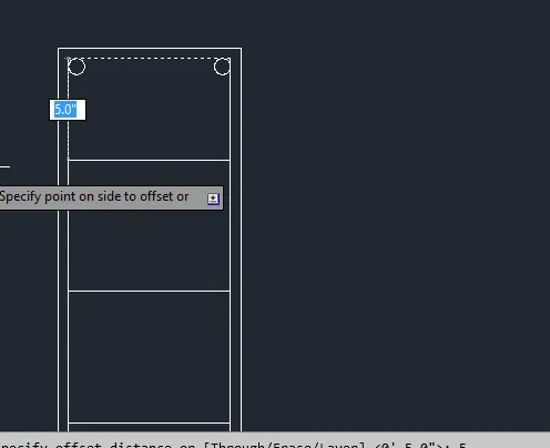
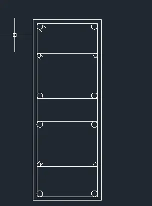
Place the 20mm dia bars in the 4corner edge of a line both the sides
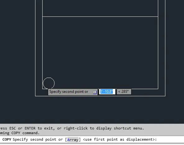
Again create a bar of dia 12mm and place the bars inner 6 corner edges of a offset line
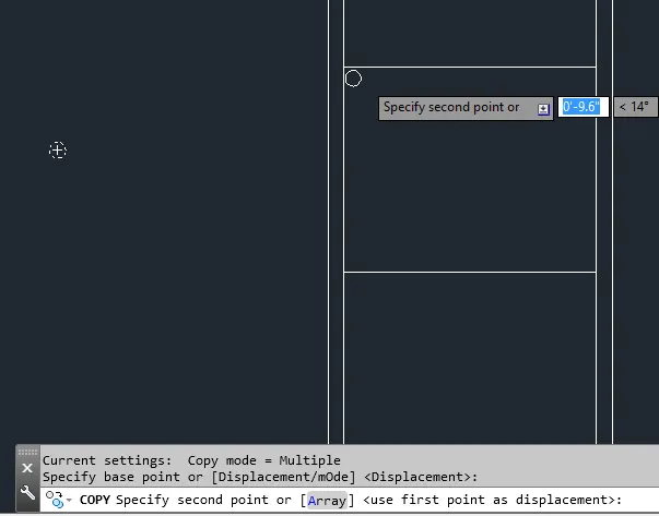
and draw a stirupps using line command and tie 3 bars with stirrups
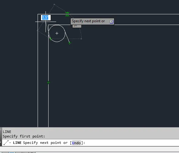
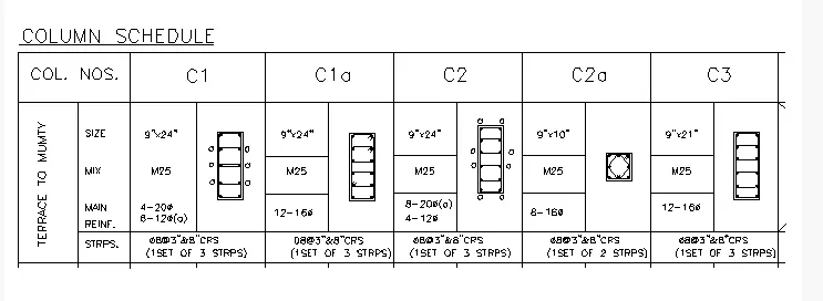
Again same procedure has been followed for C1a and C2 because of same length and breadth, so copy the columns for C1a and C2
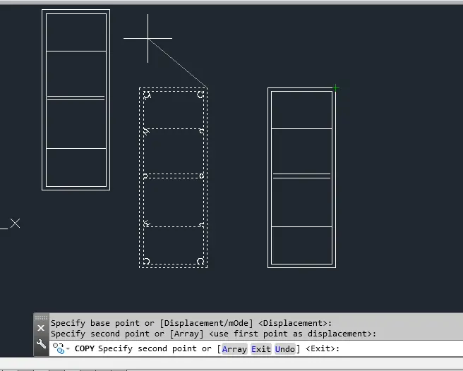
For C1a column add 12 nos of 16mm dia bars for each 12corners
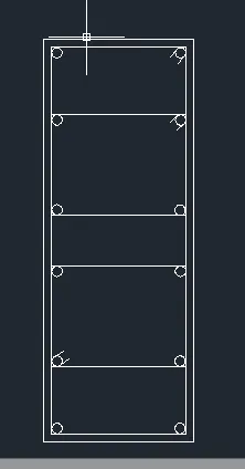
For C2 add 8nos of 20mm dia and 4nos of 12mm dia
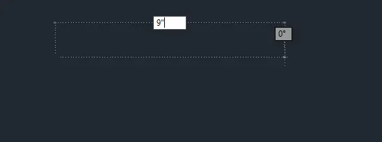
In order to create a C2a draw a column of 9"width and 10" height using line tool
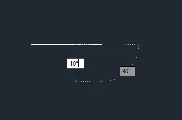
And a column height of 10" using line tool
Take offset of 0.5" using offset comand to add a cover to a column
Create 8nos of 16mm dia of bars and place the bars inside the column on each end
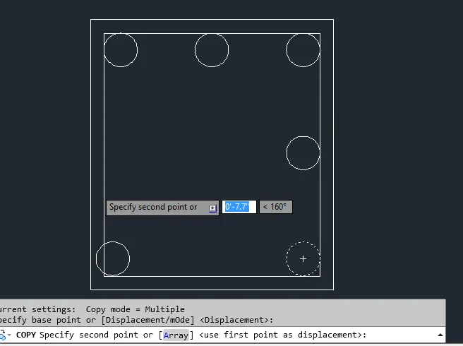
Draw a stirrups using line command to the bars
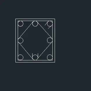
Next to draw a column C3 draw a line of width 9" and height 21" using line tool
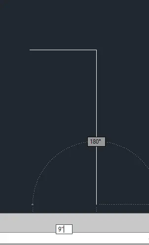
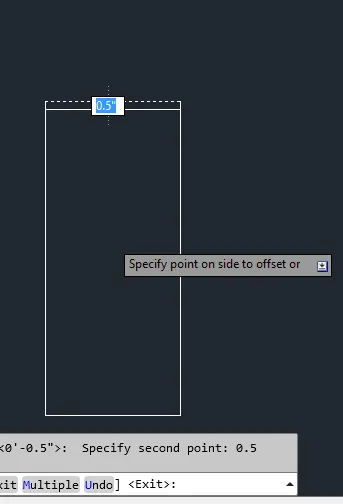
Take a offset of 5" using offset command inside the column as a column cover
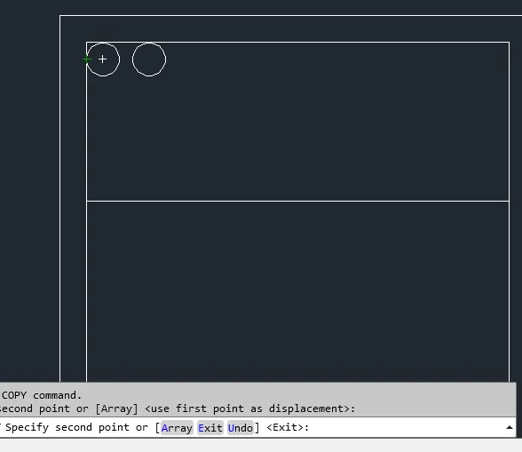
Place the 12nos of 16mm dia inside the reinforcement in the column
Finally draw a stirrups using line tool
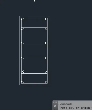
Now draw a table using table command, type table in the command box and insert table dialogue box opens and press ok
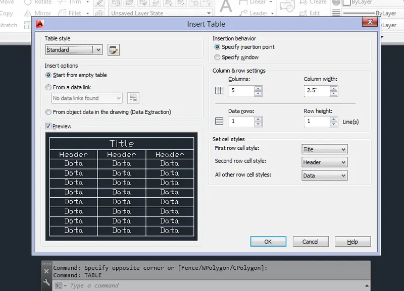
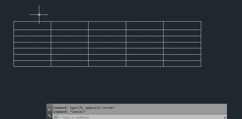
Then specify a insertion point on the screen to insert a table
Then in order to insert a text into a table, go to block attributes and there give the tag name and prompt and default name
First and foremost, give ATTDEF in the command box and the attribute definition dialogue box opens, there give the tag name and promt name and default name
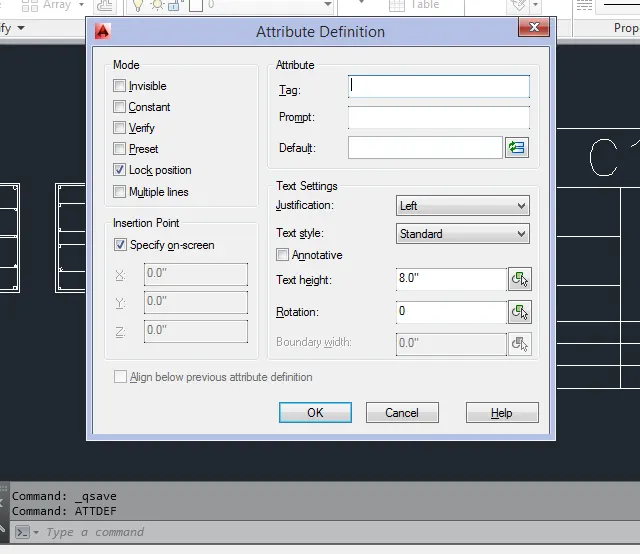
Give tag name as column name in order to get the name of the column and promt as what is the column name and default name as C1
Here we can also give the text height and text style and justification, so give justification as left and text height as 8" as per the given data
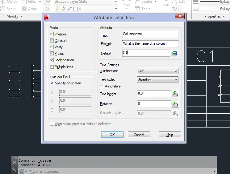
After giving all the datas, enter ok, as soon as we press ok we can find the text placed in the cursor to insert on a screen
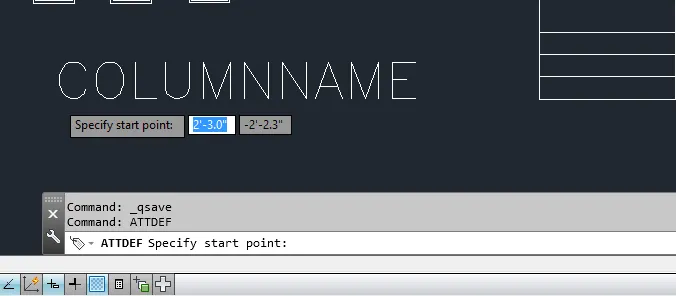
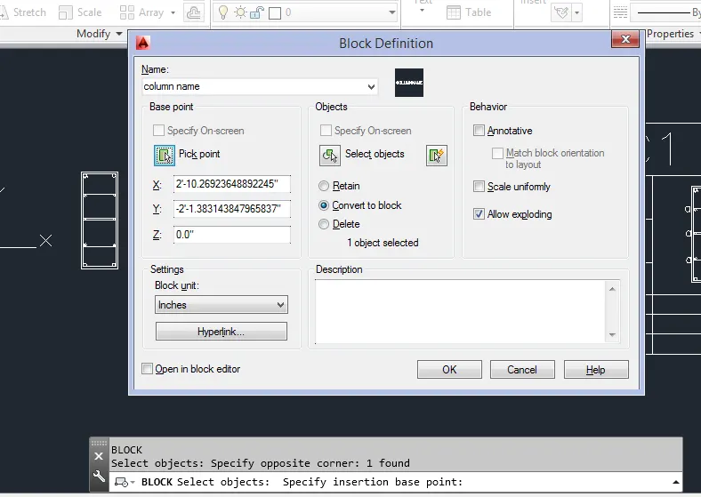
Convert this text into a block to get the attributes, so go to block command, block definition dialogue box opens and there specify a name of a block and select the objects and pick a point from the object
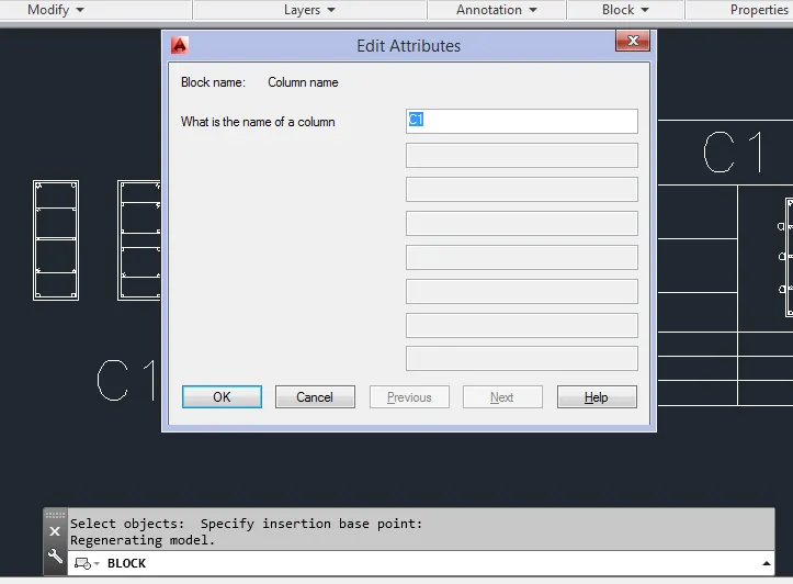
As soo as we give ok to the block definition dialogue box, edit attributes dialogue box opens and there we can find the name of a column that we had specified in attribute definition and press ok
And now we can place the obtained text into a table
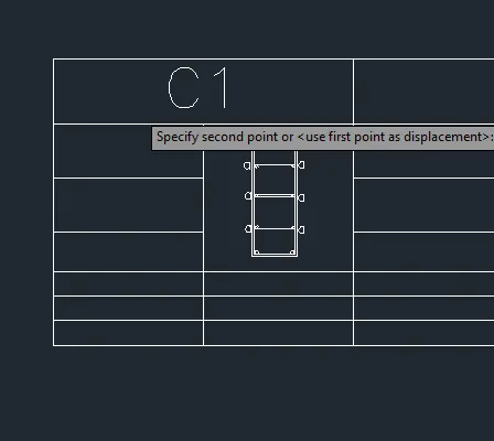
The same procedure is followed for diameter of the bar and strength of the column and size of the column
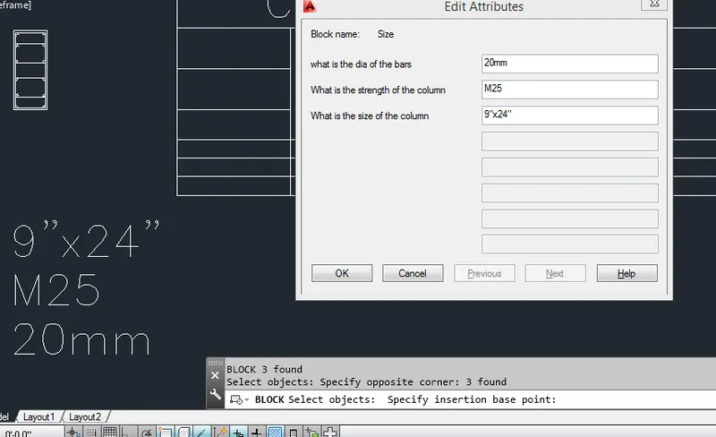
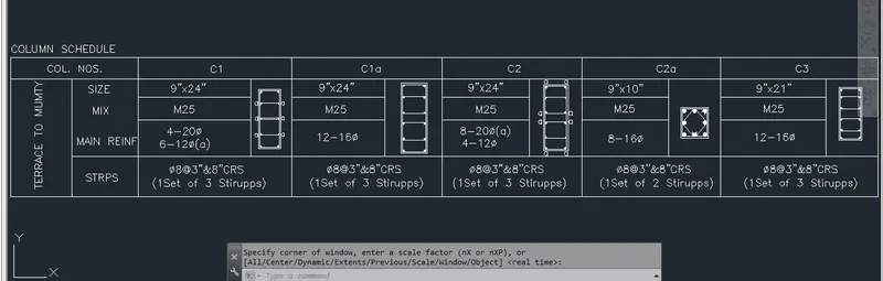
The same procedure is followed for C1a, C2, C2a, C3 columns to insert strength of the column, size of the column, name of the columns and dia of the bars
Result
2)
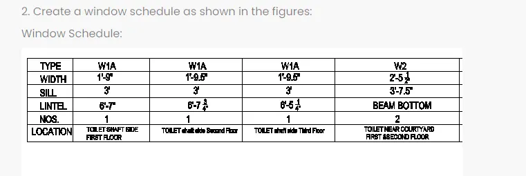
Aim: To create a window schedule using autocad
Step1
Go to start menu and open the autocad 2014 software
Give startup command and give value 1
Go to application menu and open a new file and create new file dialogue box opens and set the units to engineering, precision 0'0" and press ok
Then go units command and set the units to engineering, precision 0'0" and insertion unit as inches
Give limits command and set the limits to 500'X500'
Then give zoom command and zoom all option
Then go to table command and insert table dialogue box opens and set the no of columns and no of rows and give enter
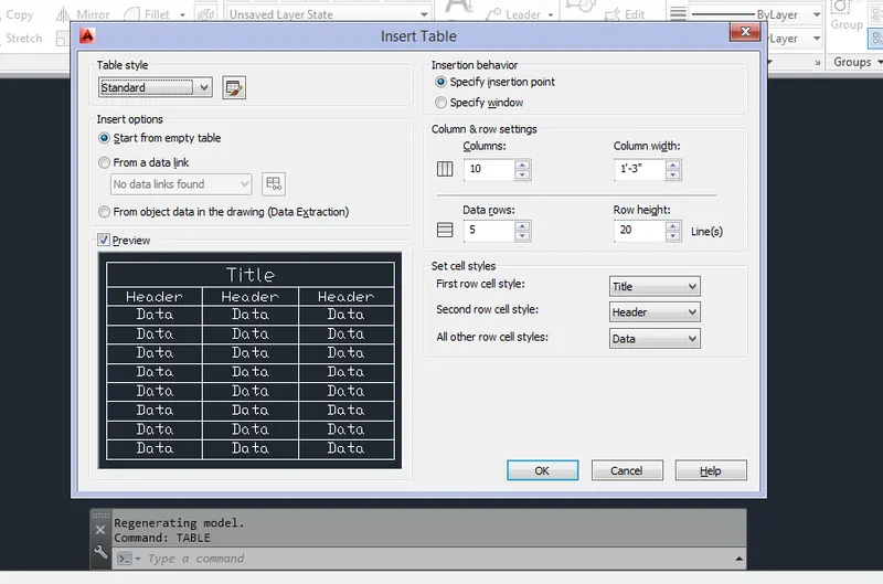
We can find the table which is attached to the cursor after giving ok and then specify the insertion point on the screen
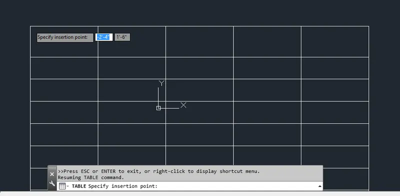
To add the text into a table, go to dtext command and specify start point of the text in this command there is a option called justify 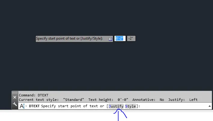
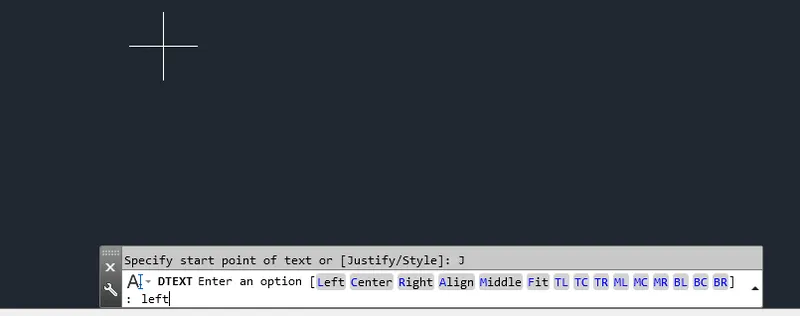
Justify the text to a left
"
Specify a height of a text, given height of a text is 8"
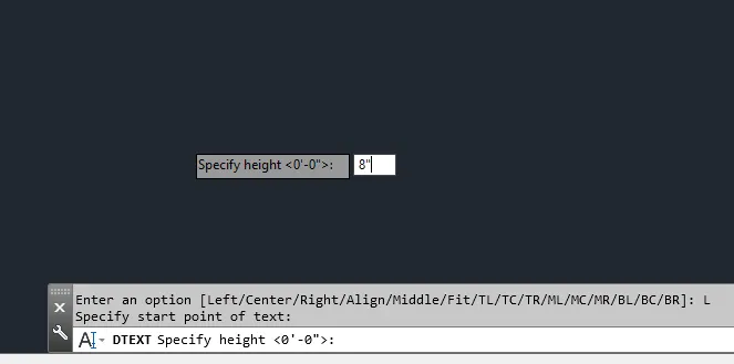
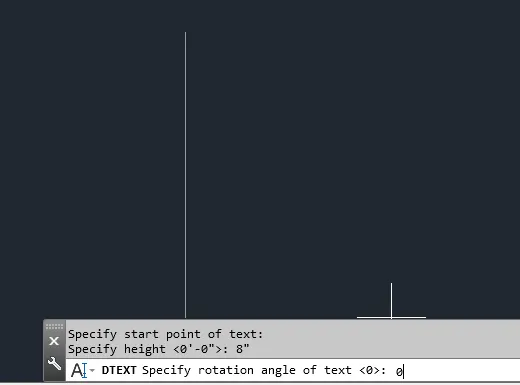
Specify a rotation angle as 0degrees and press enter
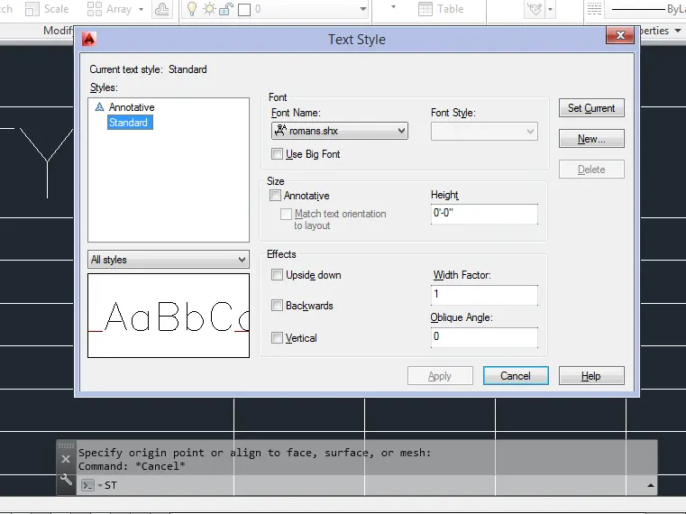
And type the text type that we want and set the text style as romans in ST command i,e style (text style)
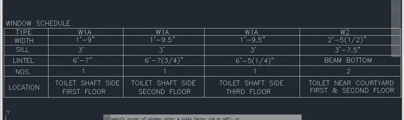
And insert the texts that we want into the table
Result
3)
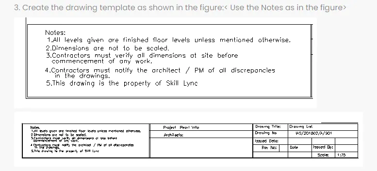
Aim: To create a given drawing template by using autocad software
Procedure:
Step1
Open the new drawing file and set the units to decimal and precision 0.0 and insertion unit as millimeters
Set the limits as 500'X500' by using limits command
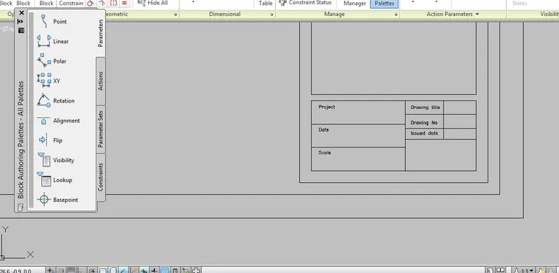
Go to layout space and in the bottom right click on the layout and there we can find the from template option
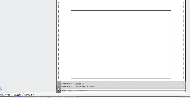
Click on the from template option and select from template file dialogue box opens and select any one of the .dwg, .dwt and .dwf file and give enter
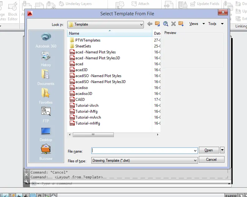
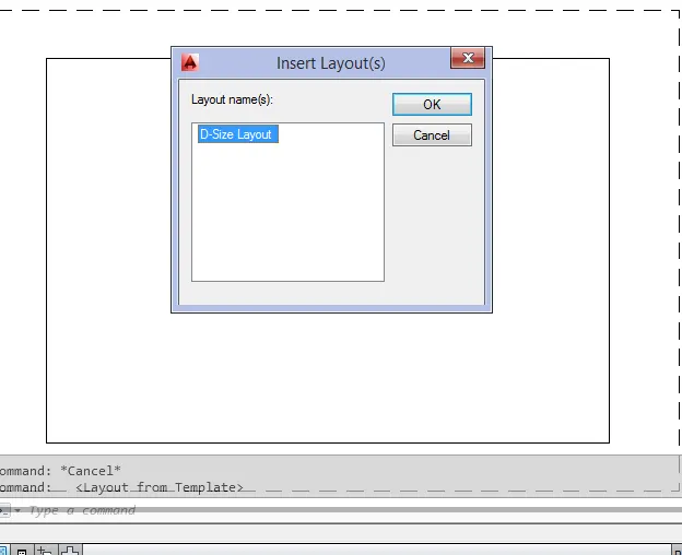
Select one of the template file and then click on open button and the insert layout dialogue box opens and select the layout and give ok and template file will open in the layout space
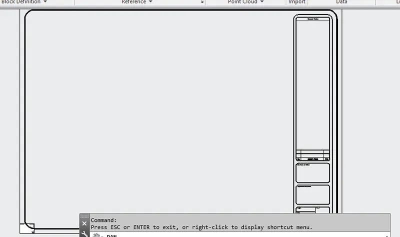
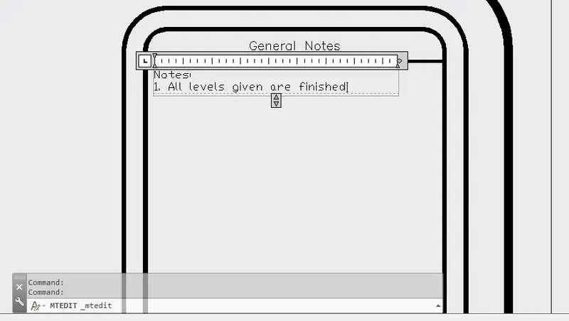
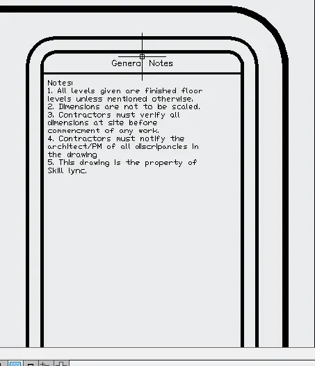
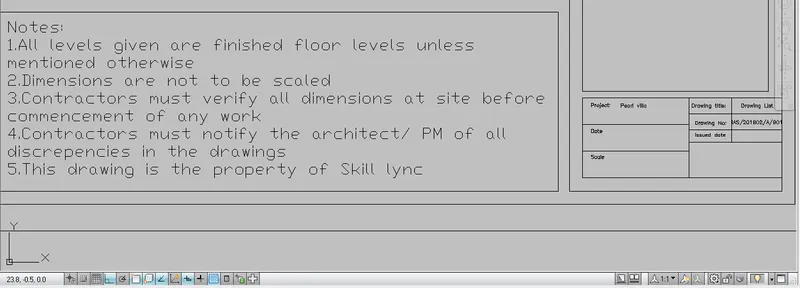
To insert a note to the template, go to multiline text command and insert a notes by using multiline command
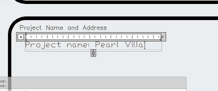
Give the project name as given in the data
Then the template has been created
Result:
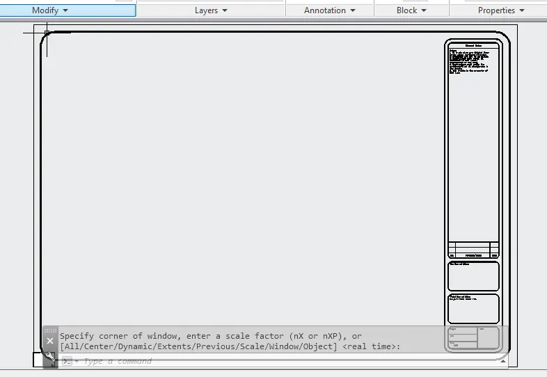
We can also edit the template by Bedit command as the template is a block which is already created by someone
Result:
4)
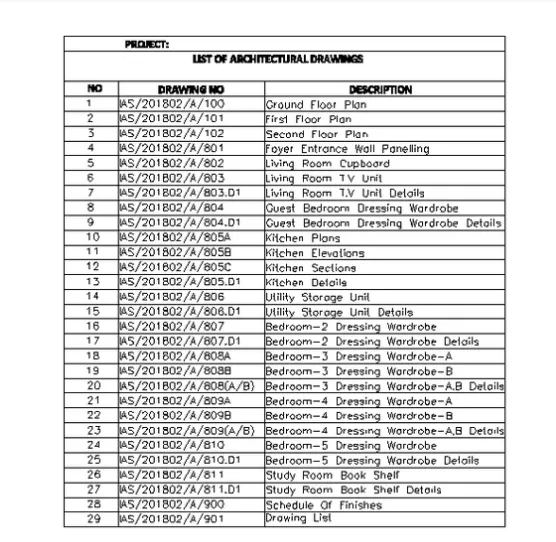
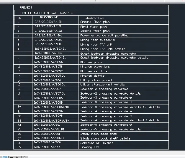
Aim: To create a list of drawing schedule as given by using autocad
Procedure:
Open a new file and set the units to decimal, precision 0.0 and insertion scale as millimeters
Go to table command, and insert table dialogue box opens and select the table rows and columns and set cells styles
Specify first row cell style as title, second row celll style as title and all other row cell style as data and press ok
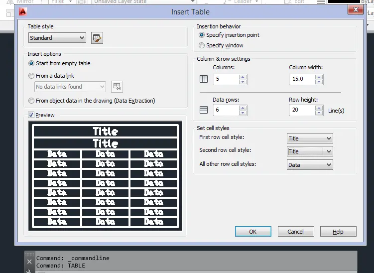
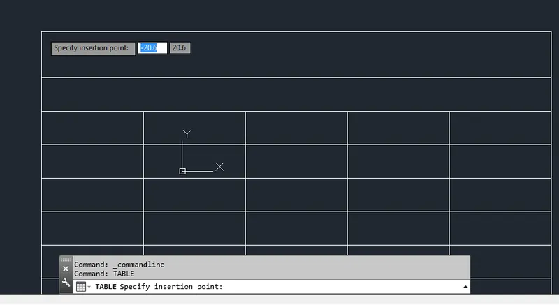
As soon as we press ok we should specify a insertion point on the screen to insert a table
To insert a text, go to single line option and give specific text height
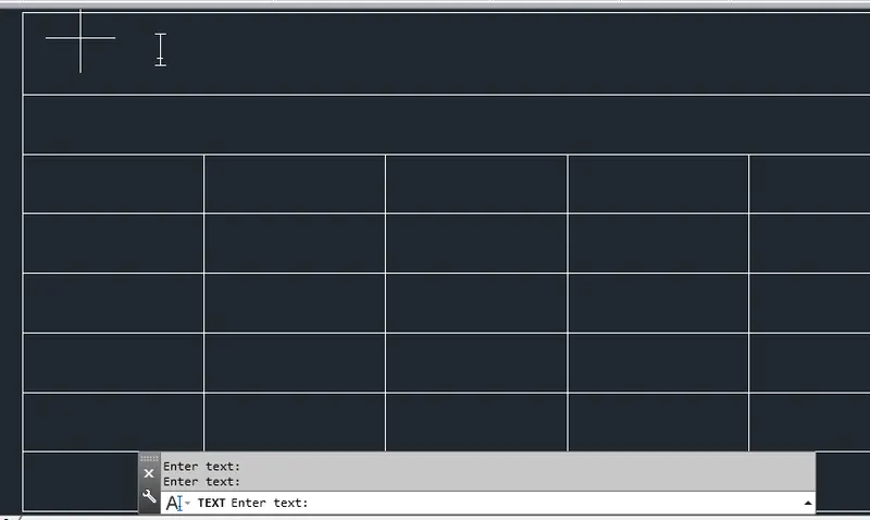
And keep on adding the texts one below the other
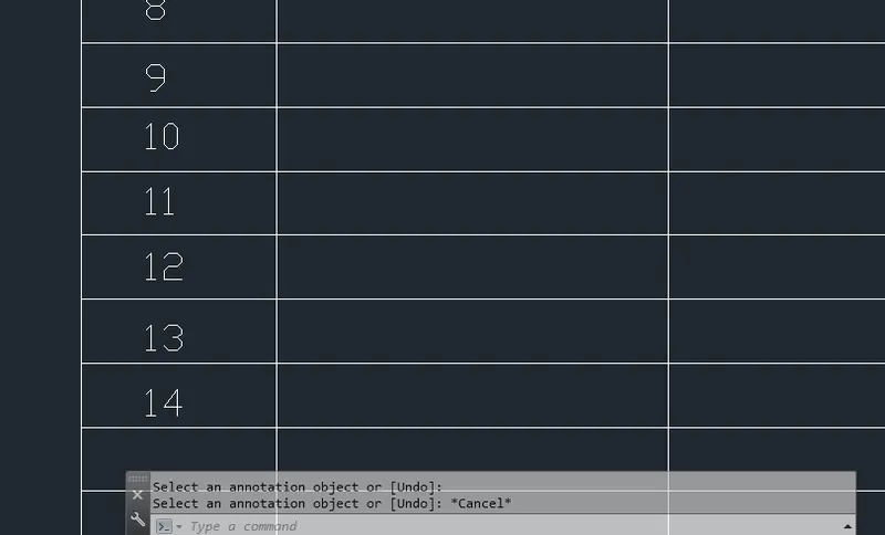
Result:
5)
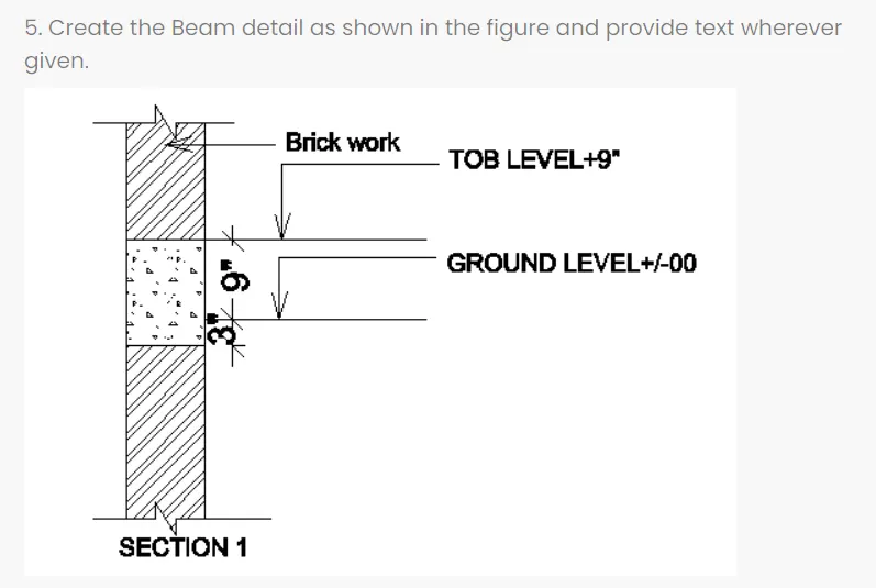
Aim: To create a beam detail as shown in the figure by using autocad
Procedure:
Go to start menu and open Autocad 2014 software
Give the command Startu and give the value1
Go to application menu and click on new, create new drawing dialogue box opens
In this dialogue box set the units to engineering units and precision is 0'-0.0" and press finish
Go to unit command and set the units to engineering units and precision 0'-0.0" and insertion scale as inches
Give the limits command and specify the lower left corner value as 500' and upper right corner value as 500'
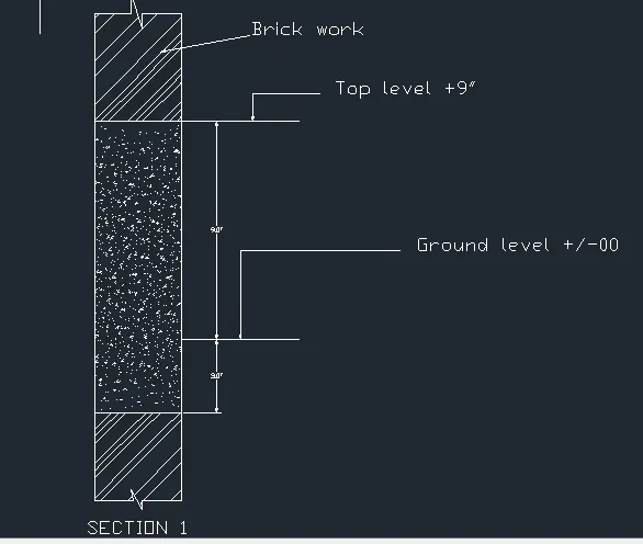
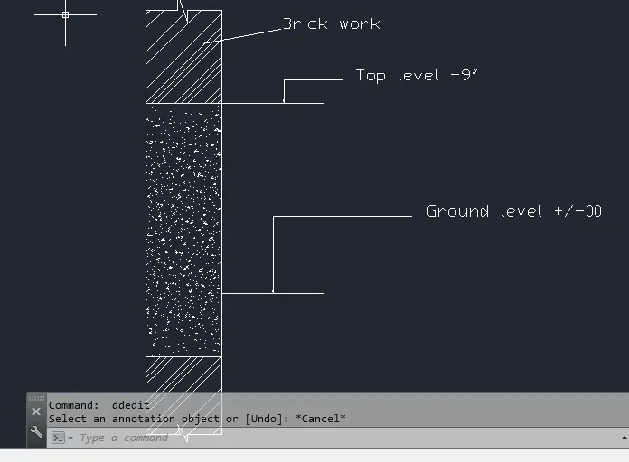
Take a line command and draw a ground level line
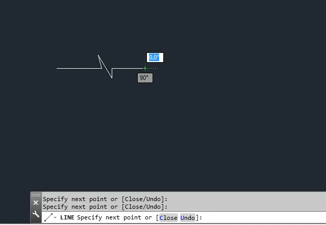
Again draw a line vertically upwards
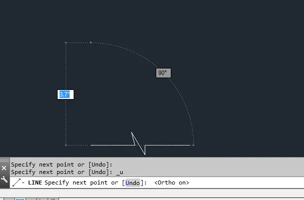
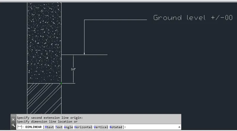
Draw a 3" line vertically upwards for the ground line
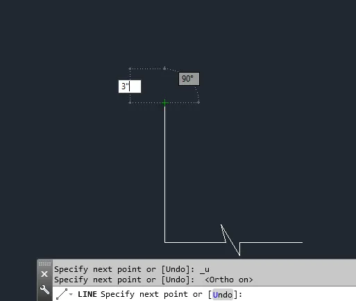
Again 9" for top level surface using line tool
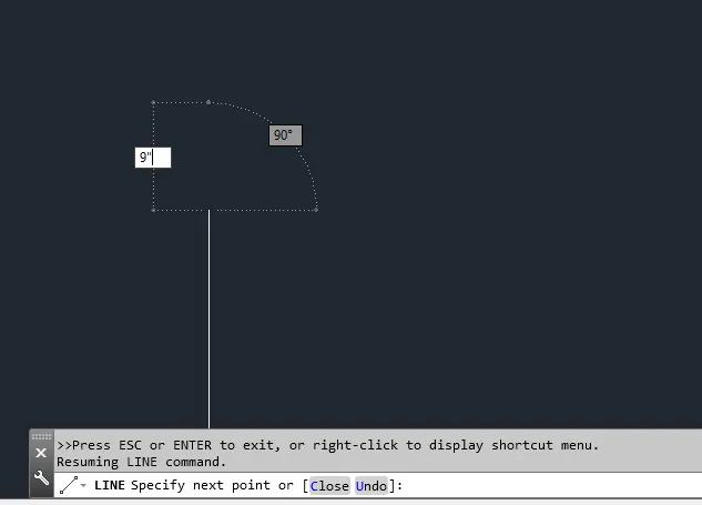
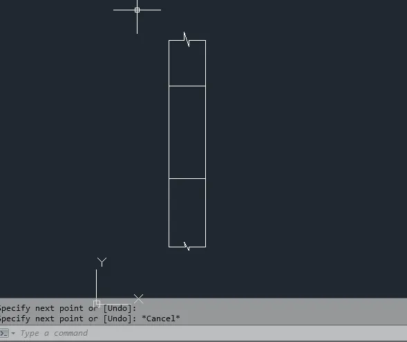
And Go to hatch command in the command box
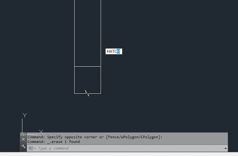
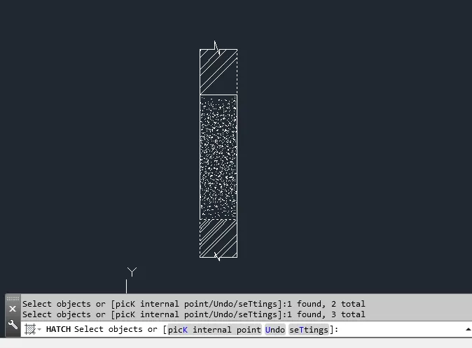
Hatch for ground level surface and top level surface by AR concrete type of hatching
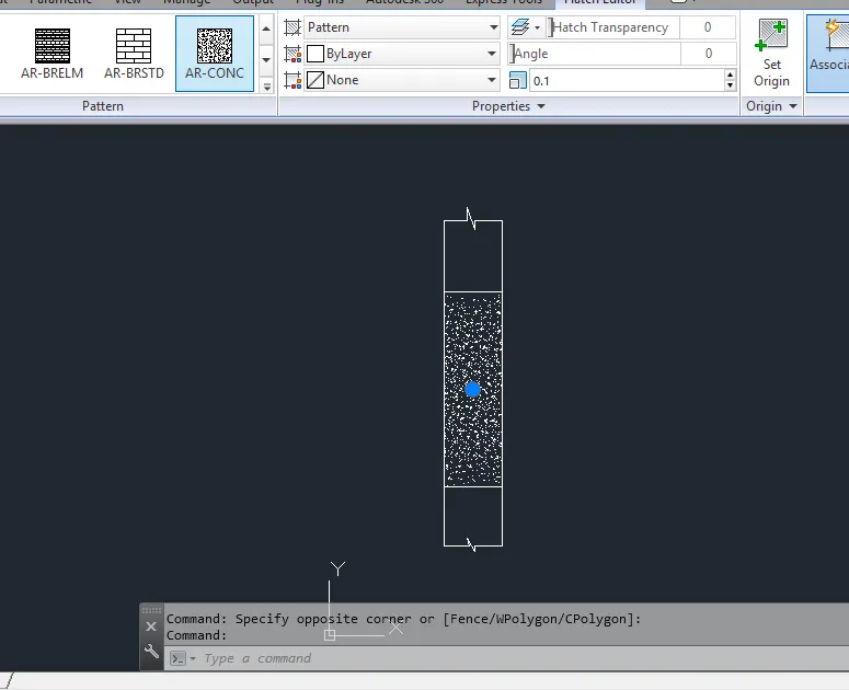
And hatch remaining portion by brick work hatching type
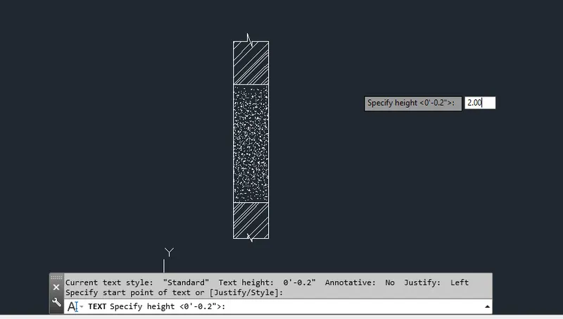
Add a text by using single line text and specify the text height as 2"
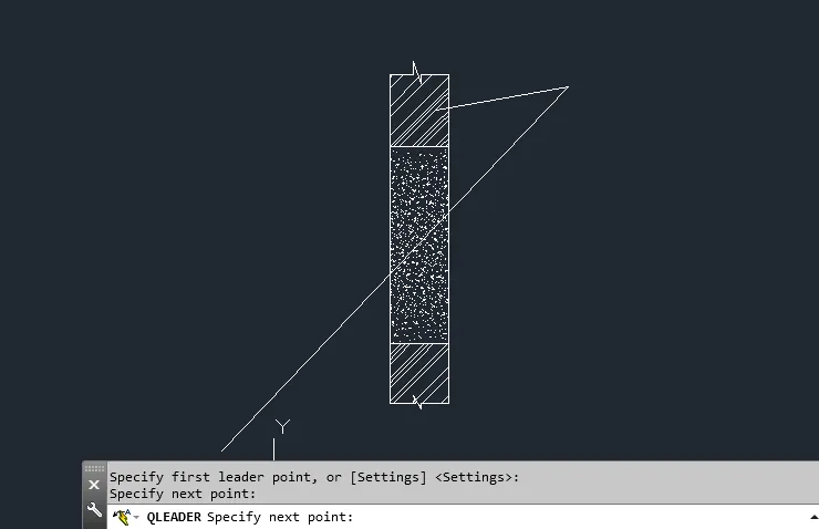
Or add a text by Qleader by using Qleader command
Measure the dimension using dimension command
Result: