Creation of Column Schedule and Drawing Template using AutoCad
AIM:
Creation of Column Schedule and Drawing Template using AutoCAD
.
INTRODUCTION
To draw the given sketch of Column schedule, Window Schedule & Templates using AutoCAD
Creating Colum schedule as per Engineering standard practice.
Window schedule to identifies easily the sizes of windows.
Drawing template & Schedule shows to identifies the project name, drawing list & drawing number mentioned in Title block.
Beam detailing as shown in sketch.
Commands used:
Polyline/Line, Multi-text/Text, Donuts, Offset, Extend, Mirror, Trim, Move, Rotate, Annotate.
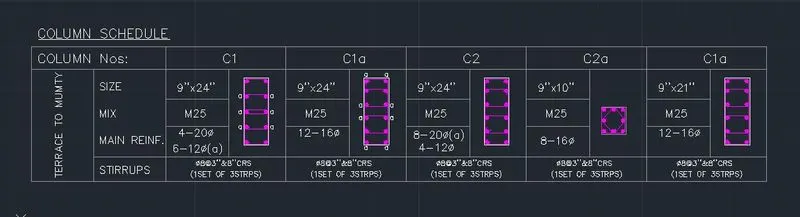
- Create a column schedule as shown in the figure.
Note: Create a column schedule with the help of lines. Also, insert text with the help of Dtext command or Single Line text.
Hint: Use font name: romans.shx; Height: 8”, Justify: Left
PROCEDURE
Column Schedule:
New sheet-Units-Engineering-precision 0’.0’’ feet & OK.
First create table as shown in sketch using command: L Line
Command: ST Text Style, > select font text name (romans.shx) > text size 8’(ht.)
Command: T Text, using this to text the given in the drawing are as follows,
Column C1 is provided 4-20 Ø, & 6-12 Ø, the 12 Ø bars are marked with ‘ a ‘
Column C1a & Column C3 are provided with 12-16 Ø bars.
Column C2 is provided with 8-20 Ø & 4-12 Ø, the 20 Ø bars are marked with ‘a’
Column C2a is provided with 8-16 Ø bars.
All columns are provided with 8 Ø stirrups with 3’’ spacing cc near the ends & 8’’ cc in mid-length. The clear cover for all the columns is assumed to be 1.5’’ , as per IS 256 the minimum cover to the column should not be less than 1.5’’.
Give the heading Column Schedule using multi-line text & underline it.
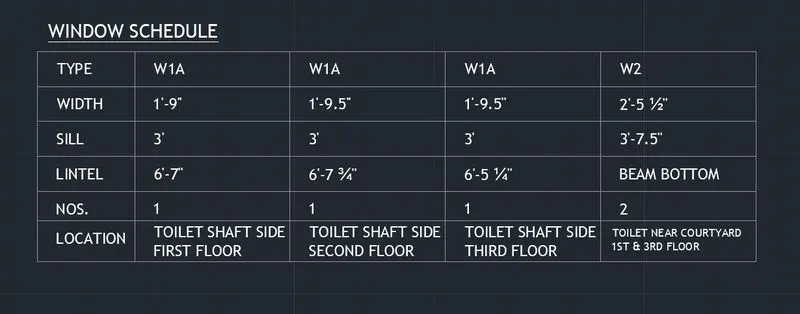
- Create a window schedule as shown in the figures:
PROCEDURE
Window Schedule:
New sheet-Units-Engineering-precision 0’.0’’ feet & OK.
First create table as shown in sketch using command: L Line
Command: ST Text Style, > select font text name (romans.shx) > text size 8’(ht.)
Command: T Text, using this to text the given in the drawing.
Give the heading Window Schedule using multi-line text & underline it.
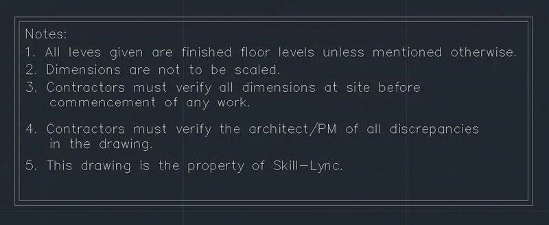
- Create the drawing template as shown in the figure:< Use the Notes as in the figure.
PROCEDURE
Drawing Template:
New sheet-Units-Engineering-precision 0’.0’’ feet & OK.
First create table as shown in sketch using command: L Line
Command: ST Text Style, > select font text name (romans.shx) > text size 8’(ht.)
Command: T Text, using this to text the given in the drawing.
Give the heading Drawing Template using multi-line text & underline it.
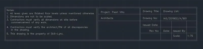
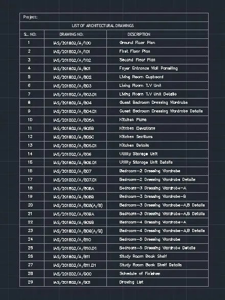
- Create the list of drawing schedule as shown in the figure:
PROCEDURE
Drawing Schedule:
New sheet-Units-Engineering-precision 0’.0’’ feet & OK.
First create table as shown in sketch using command: L Line
Adjust the size of rows & columns.
Command: ST Text Style, > select font text name (romans.shx) > text size 8’(ht.)
Command: T Text, using this to text the given in the drawing.
Enter the data, Make the contents of title & header rows as Bold.
Give the heading Drawing schedule using multi-line text & underline it.
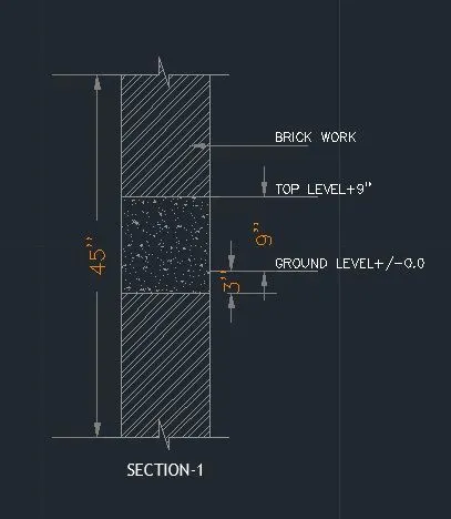
- Create the Beam detail as shown in the figure and provide text wherever given.
PROCEDURE
Beam Detail:
New sheet-Units-Engineering-precision 0’.0’’ feet & OK.
Make two parallel lines 45’’ long at a distance of 6’’ from each other.
Using the break line command, make a break line at the top & bottom.
Make a horizontal line as Ground level */-00
w.r.t GL make a horizontal line as Top level 9’’
Command: T Text, using this to text the given in the drawing.
Give the hatching of brickwork & concrete as shown.
RESULT:
- The Given Sketch of Column Schedule is drawn using AutoCAD.
- The Given Sketch of Window Schedule is drawn using AutoCAD.
- The Given Sketch of Drawing Template is drawn using AutoCAD.
- The Given Sketch of Drawing Schedule is drawn using AutoCAD.
- The Given Sketch of Beam section detail is drawn using AutoCAD.