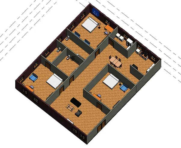
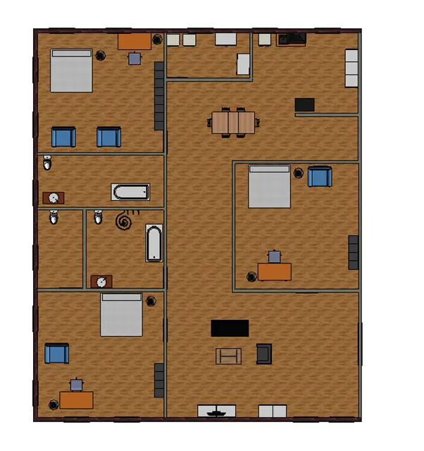
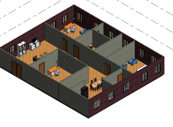
Creating Walls, Partition walls and Floors for a residential layout using REVIT
1) Use the project file created from Week 2. Use it for this assignment. Based on your layout from week 2, using floor tool under architecture tab and select the floor with appropriate material and thickness using the property browser create a layout in the Ground floor Level. Align the floor plan with grids created from week 2
Aim:
Creation of the floor with specific material and thickness
Procedure:
I. Open the project file
II. Open Revit from the window and then in the Revit tab
III. click on the file option
IV. then click on open
V. next browse for the file project 1 ( which was saved previously) to open and click on it
VI. CREATION OF THE FLOOR
VII. In the architecture tab select the floor option
VIII. Then click on the line option
IX. With the help of the grid lines created previously draw the boundary of the lines with the snapping option
X.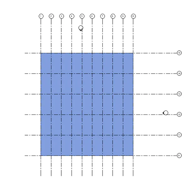
XI. Now go to the properties bar
XII. Click on the floor icon
XIII. Then there will be drop down of the different types of the floor
XIV. Here select the standard timber-wood floor
XV. For changing the thickness of the floor
XVI. Click on the edit type in the properties bar
XVII. Then in the structure option click on the edit
XVIII. Next specify the required thickness of the structure as shown un the figure below
XIX.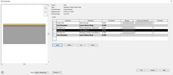
XX. Next click on the insert if you want to add the extra material
XXI. In the material column we can change the any material if required
XXII. Then click ok
Result:
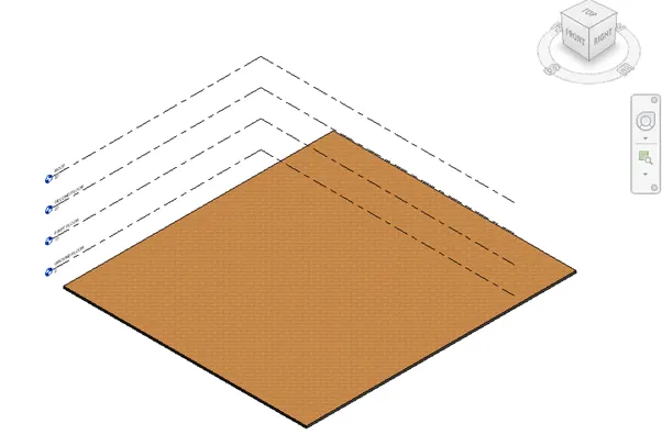
Required floor was created in the Revit
2) Add walls based on the floor layout. Pick lines or use the draw tool to modify the boundary of walls. Use the property browser to select appropriate material and thickness for walls. After creating the walls verify using the property browser to see if the top and bottom of the walls are constrained.
Aim:
Addition of the wall to the layout created
Procedure:
I. By the project browser go the ground floor, floor plan
II. Go to the menu bar
III. And select the architecture toolbar
IV. Here selects the wall option
V. With the snapping option click on the first point
VI. Then click on the next point by snapping
VII. Similarly carry out until where the wall is going to end
VIII. Press esc
IX. Click on the wall if wall has to be edited
X. Then click on the edit profile in the menu bar
XI. There will be popup for selecting the elevation view or the 3d view
XII. Select the required view
XIII. Pick the line option is selected in draw options
XIV. Select the line which has to be moved or copied as shown below
XV.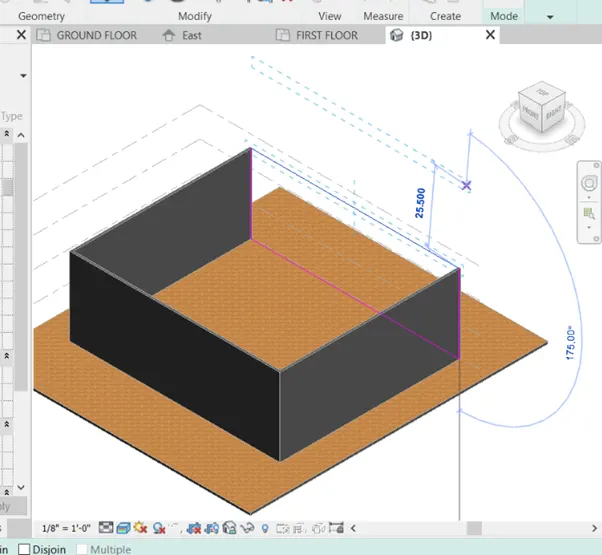
XVI. Similarly if want to change the dimensions of the wall
XVII. Draw the line where ever required as shown in the figure below
XVIII.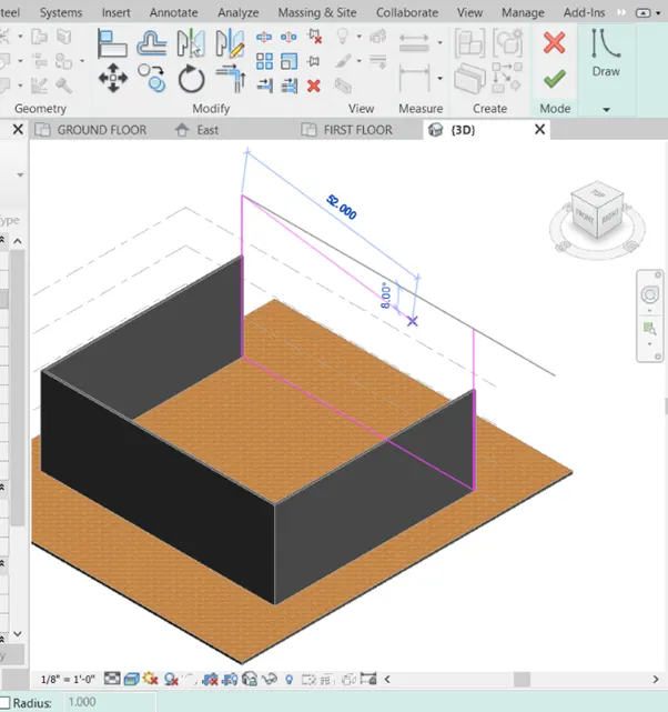
XIX. Use the property browser to select appropriate material and thickness for walls
XX. Now go to the properties bar
XXI. Click on the wall icon
XXII. Then there will be drop down of the different types of the wall
XXIII. Here select the generic 200mm
XXIV. For changing the thickness of the wall
XXV. Click on the edit type in the properties bar
XXVI. Then in the structure option click on the edit
XXVII. Next specify the required thickness of the structure as shown in the figure below
XXVIII.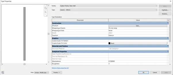
XXIX. In the material column we can change the any material if required
XXX. Click on the material option
XXXI. And search for the required material
XXXII. Load the material and ok
XXXIII.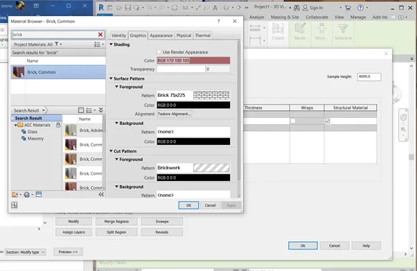
XXXIV. Then click ok
XXXV. After creating the walls verify using the property browser to see if the top and bottom of the walls are constrained
XXXVI. Go to the property browser
XXXVII. Click on the wall and select them
XXXVIII. In property browser check the base constraint to the ground floor
XXXIX. Check the top constraint and if it shows unconnected
XL. Click on the unconnected there will be the drop down of the different levels
XLI. Select the required level i.e., first floor
XLII. Then all walls selected will be limited to the first floor.
XLIII.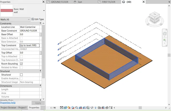
Result:
Walls for the layout with the required properties were created
a. Based on your observation, what is beneficial for connecting walls with associated levels rather than being Unconnected
connecting the walls with the help of the constraints is more beneficial as it automatically attaches to the required floors that are mentioned in the top constraints and bottom constraint in the properties browser respectively.
b. Which option is convenient for modeling walls, By Height or By Depth?
For me, by height option is very convent work on creating the walls as it helps in modelling to the exact positions and over the floor as the modelled wall would be visible if working in the 3d view
If we are working in the by depth option floor will be blocking the view of the modelling the structure
3) Copy the model elements ( wall, floor ) modelled to Ground Floor Level and paste it aligned to First Floor Level . Use modify tab to utilize copy and paste options to align elements to a different level
aim:
copying the selected objects to the required level
procedure:
I. In the Revit window
II. By dragging the cursor for right to left cover all the instances created
III. Which selects all the instances i.e., walls and floors
IV. In the menu bar click on the copy to clipboard
V. Next, in the menu bar click on the paste option
VI. And in the drop down select the aligned to selected levels
VII. Next select the first floor
VIII. Click ok
Result:
Coping the walls and floors to the required levels was done
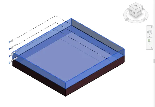
4) Use interior partition walls to create separate rooms within your residential unit. The model must include the following rooms
a. Living Room/ Drawing Room ( 15’ X 18’)
b. Dining Room (9’ X 11’)
c. Bed Room ( 9’ X 12’ and 15’ X 11’)
d. Rest Room ( 10’ X 12’ )
e. Kitchen (8’ X 10’)
The above are for examples. You can use them or use your measured entities to create your model based on your layout. You may include entry walkway, Patios or Guest rooms based on your creativity and purpose of modeling. Convert units if you are using metric system
Aim:
Modelling the 3d residential unit for the required dimensions
Procedure:
I. in a paper plan the position of the interior walls
II. Go to the menu bar
III. And select the architecture toolbar
IV. Here selects the wall option
V. With the snapping option click on the first point
VI. Then click on the next point by snapping
VII.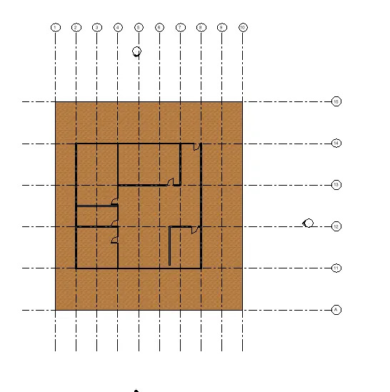
VIII. Similarly carry out until where the wall is going to end
IX. As grids all ready present and using the snapping option
X. Click on the position of the interior wall where it has to started
XI. Click the next point
XII. Similarly create the walls where ever required as referring the sketched in the on the paper
XIII. Esc
Result:
All separate rooms were modelled in the layout
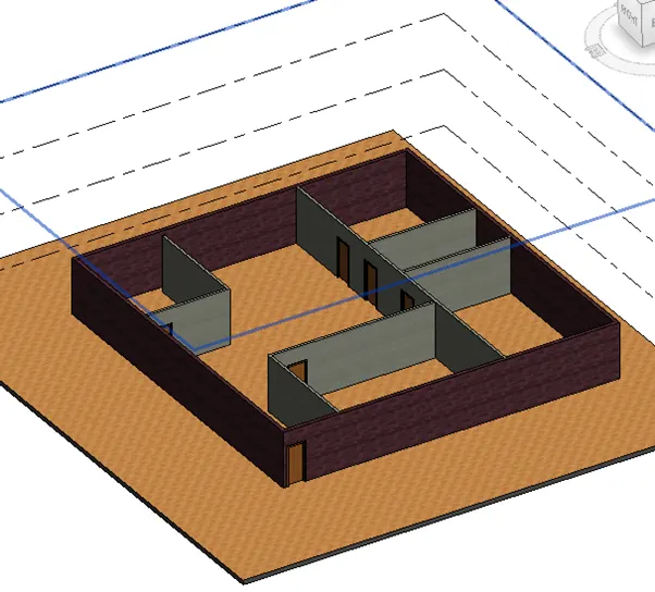
5) Based on week 2 assignment, the components to be included in a residential unit were inserted to the Revit file. Place these components in appropriate locations to add details to your residential model
Aim:
Placement of the components in the model
a. Place Doors and windows in the wall at appropriate locations
I. Next got o the architecture tool bar and select the door option
II. Clicking on the door in the properties bar select the type of the door
III. Now with the help of the snapping place the door
IV. Move the cursor on the wall where the door has to be placed and snap on the wall
V. Next go to the architecture tool bar and select the window option
VI. Clicking on the window in the properties bar select the type of the window
VII. Now with the help of the snapping place the window
VIII. Move the cursor on the wall where the window has to be placed and snap on the window
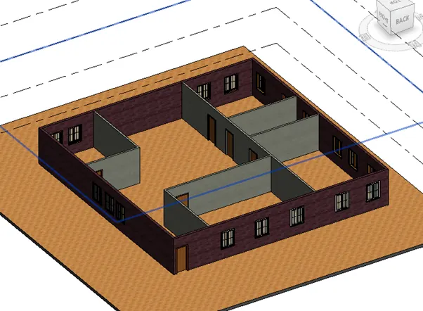
b. The Living Room must include furniture set, couch table and TV desk and shelf cabinets
I. Go to menu bar
II. Select the architecture tab
III. Now select the component option
IV. In the properties tab drop down select sofa the required size
V. And by snapping place the component at the required position
VI. In the properties tab drop down select coffee desk the required size
VII. And by snapping place the component at the required position
VIII. In the properties tab drop down select tv the required size
IX. And by snapping place the component at the required position
X. In the properties tab drop down select chair the required size
XI. And by snapping place the component at the required position
XII. Click on the chair
XIII. And the in-menu bar selects the rotate
XIV. Then specify the direction and type 90
XV. Therefore chair is rotated to the required angle
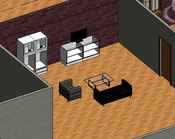
c. The Dining Room must include a table and chairs serving the purpose of eating
I. Go to menu bar and select the architecture bar and
II. Click on the component option
III. Next click on the load family
IV. In the popup tab in the following categories
V. Select the uk> furniture> dinning> table with seater
VI. In the properties tab drop down select table the required size
VII. And by snapping place the component at the required position
VIII. Esc
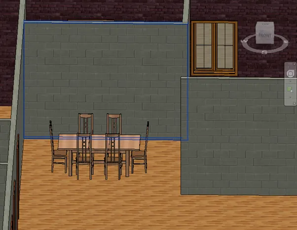
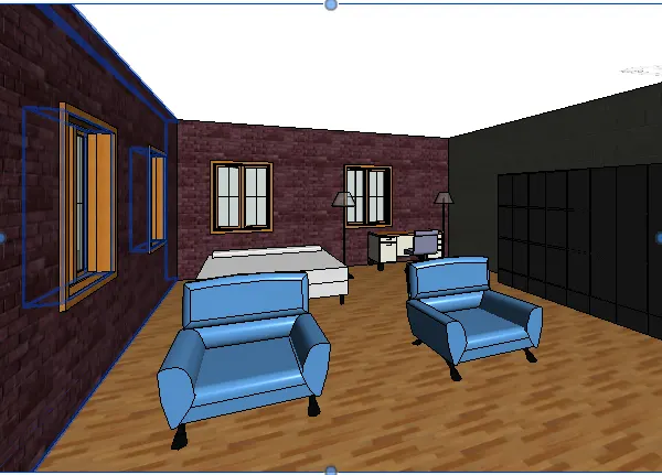
d. Bed Room must include a bed set, shelf, lighting and individual study desk and chair
I. Go to menu bar and select the architecture bar and
II. Click on the component option
III. Next click on the load family
IV. In the popup tab in the following categories
V. Select the elements like bed , lighting, chair and desk and storage units
VI. In the properties tab drop down select table the required size
VII. Go to properties browser
VIII. Clicl on the component
IX. And select the required component by drag down
X. And by snapping place the component at the required position
XI. Esc
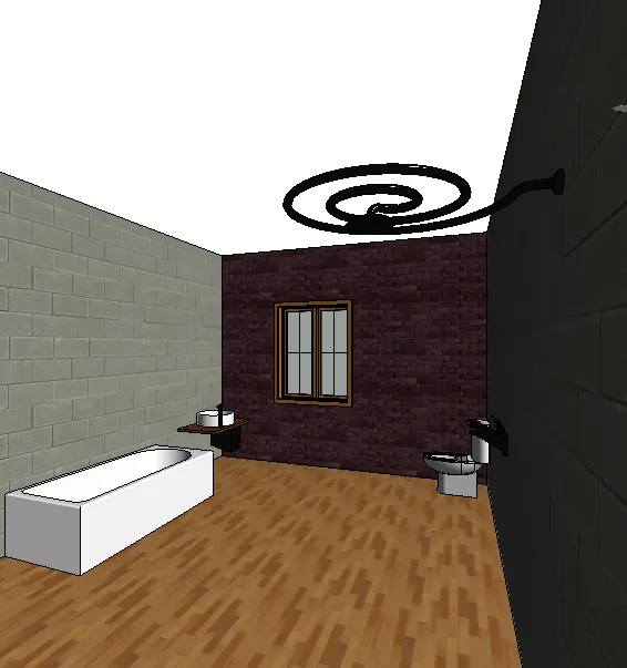
e. Rest room should include bath tub and plumbing fixtures discussed in class
I. Go to menu bar and select the architecture bar and
II. Click on the component option
III. Next click on the load family
IV. In the popup tab in the following categories
V. Select the elements like plumbing and fixtures
VI. Ok
VII. Go to properties browser
VIII. Clicl on the component
IX. And select the required component by drag down
X. And by snapping place the component at the required position
XI. After selecting the tap
XII. In the properties browser provide the height in the elvation from the ground level as 3’
XIII. And snap on the required positions on the tap
XIV. Also for the sink
XV. Esc
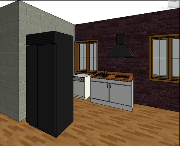
f. Kitchen should include countertops, gas stove cabinet and shelves to store food items
I. Go to menu bar and select the architecture bar and
II. Click on the component option
III. Next click on the load family
IV. In the popup tab in the following categories
V. Select the elements like SPECILITY EQUIPMENTS and domestic
VI. Select the refrigerator, kitchenets storage units etc
VII. Ok
VIII. Go to properties browser
IX. Clicl on the component
X. And select the required component by drag down
XI. Also for the sink
XII. Esc
g. The wash/storage room can include washing machines and shelves to store clothes
I. Go to menu bar and select the architecture bar and
II. Click on the component option
III. Next click on the load family
IV. In the popup tab in the following categories
V. Select the elements like speciality equpments> washer dryer and shelves
VI. Ok
VII. Go to properties browser
VIII. Clicl on the component
IX. And select the required component by drag down
X. And by snapping place the component at the required position
XI. Esc
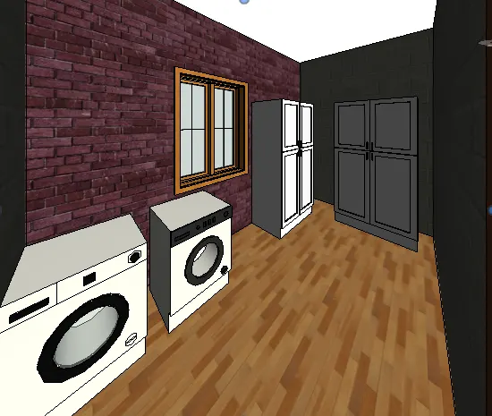
Result:
Most of the components present in the library were used to add details to the model and its place was checked with the 3d navigation and its authenticity on a real time basis to verify the model.